|
5003| 10
|
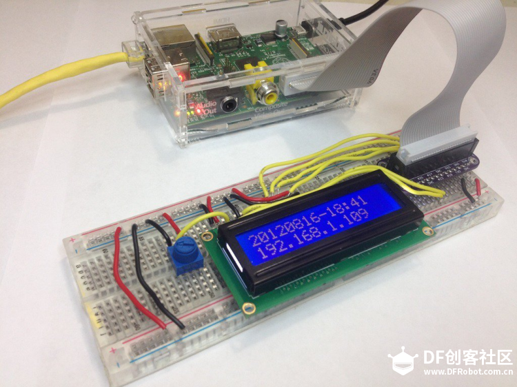
【转载】用树莓派驱动一个16×2的LCD |
 不管什么项目,如果加上一个液晶显示屏的话肯定都会看起来更棒。这篇文章将详解如何用树莓派的六个通用端口(GPIO)来连接一个廉价的HDD44780的小型LCD。当然也有用I2C或是UART来连接LCD的, 但是使用GPIO是最直接的方法。 这种方法的几个优势:
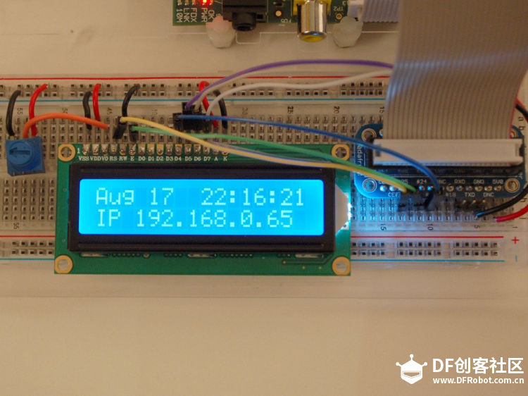
以下是用Python代码控制显示的时间日期以及IP地址。如果你的树莓派运行在Headless模式下(Headless模式是系统的一种配置模式。在该模式下系统缺少了显示设备、键盘或鼠标),能有个小的显示屏显示IP地址可是很有吸引力的。
连接Cobbler到LCD上LCD
任何一个拥有16个引脚的LCD基本上都是用HD44780控制器来控制的。 这种类型的LCD的引脚都拥有相同的输入输出功能,所以比较容易使用。LCD采用的是并行接口,这就意味着树莓派需要提供多个引脚来控制它。本篇教程中我们会用到树莓派的4个数据引脚(4位模式)和两个控制引脚。 数据引脚可以直接传输数据到LCD上, 这里我们只让LCD处于写模式,不读取任何数据。 寄存器的选择引脚有两种用途。当设置为低位时,它可以发送指令到LCD(比如显示的位置或是清空屏幕),可理解为命令寄存器。 当设置为高位的时候,它使得LCD转为数据模式并且将数据传输到屏幕上。 读/写引脚在这里会被设置成低位(写模式),因为我们只是想让LCD作为一个输出设备。 LCD 各个引脚的定义:
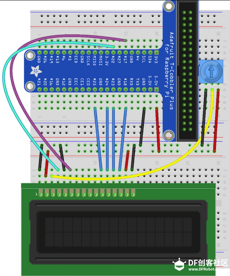
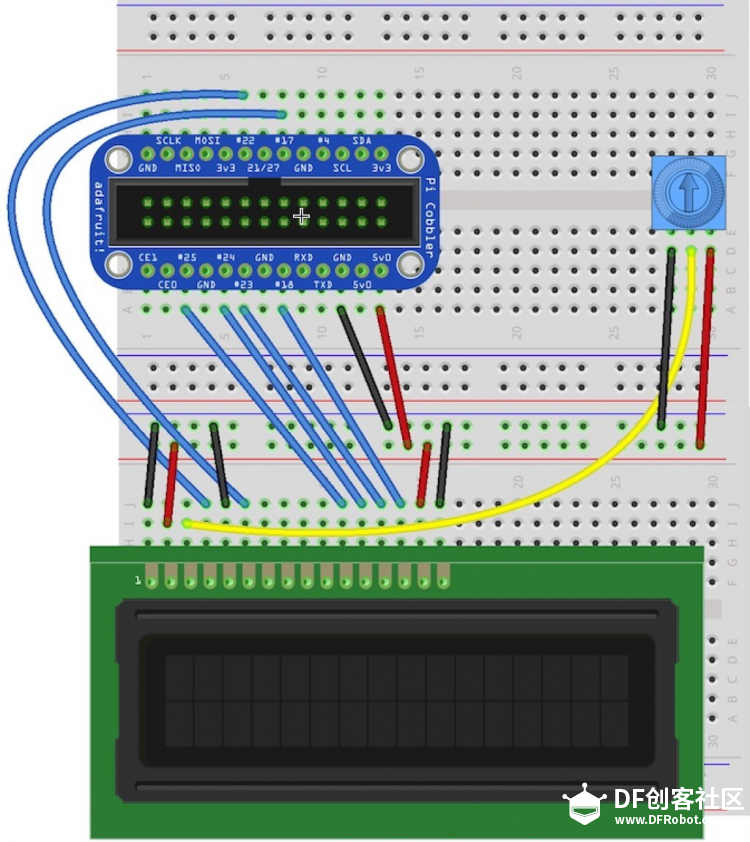
首先将Cobber的电源引脚连接到面包板的供电轨上。+5V的用红线连接到红线轨上(译者认为这里连接3.3V的就够了), GND用黑线连接到蓝线轨上, 为了能使数据传到LCD上,我们将进行以下的连接。
分压器左边的引脚接地(黑线),右边的引脚接+5V(红线)。
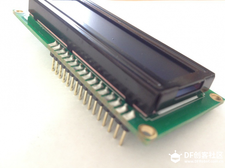
原理图5V LCD vs 3.3V Pi 树莓派配置的通用接口(GPIO)为3.3V,但是我们的LCD是需要5V配电的设备。如果我们仅仅是用LCD做树莓派的输出设备的话,连接5V的引脚当然没有问题。所以我们这里不使用Cobbler上3.3V的Pin口,并且我们将LCD上的RW(读写)脚接地,这样就避免了LCD向树莓派发送+5V的信号。 准备LCD 在你开始前,确认你有一组 0.1“规格的引脚和一个阻值为10K的分压器。  大部分LCD显示屏是需要16个引脚的,如果头部太长,可以适当剪短到合适的长度即可。 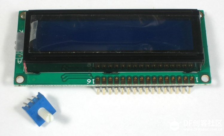 接着你需要将引脚和LCD焊接到一起。你必须这么做,不能只是扣上去就完事了。  首先将Cobbler上的+5V引脚跟GND引脚连接到面包板上。接着如图连接LCD的Pin1脚、Pin2脚、Pin15脚和Pin16脚连接到面包板的供电轨上。这个时候LCD的背光应该就亮了,如果没有亮请检查你的线路是否连接正常。 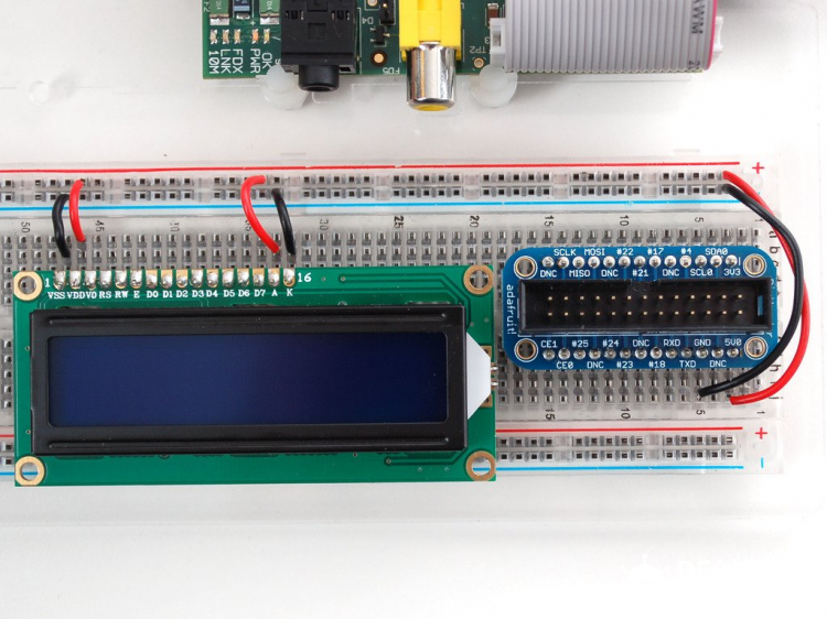 接着,将分压器中间的引脚按图中所示连接到LCD的Pin脚3上,其他两个引脚分别连接5V电源和地线。 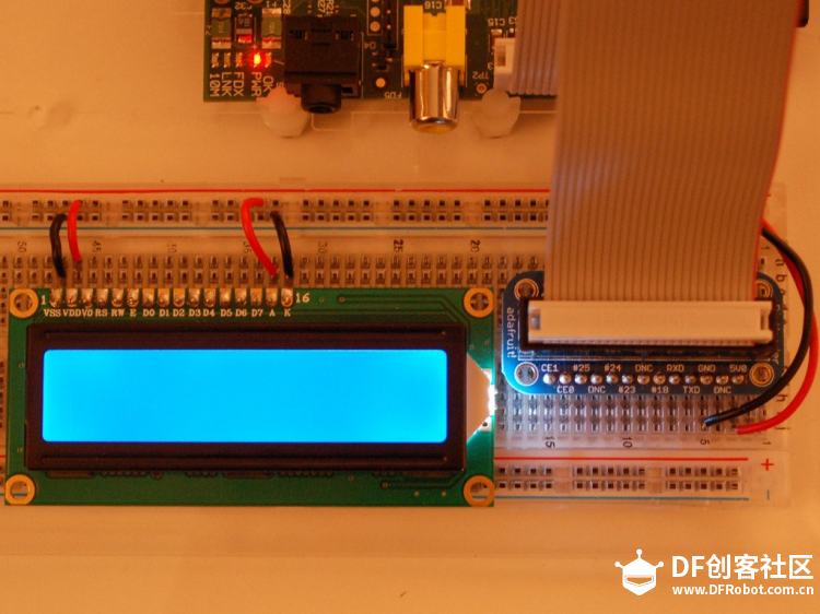 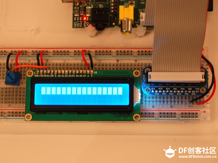 扭动分压器直到LCD的第一行显示出方块来。如果看不到,检查一下线路是否连接正确。
按照电路图所示完成LCD最后RS(Pin 4脚),RW(Pin 5脚), EN(Pin 6脚), D4(Pin 11脚), D5(Pin 12脚), D6(Pin 13脚)和D7(Pin 14脚)的连接。
到这里,就可以用Python脚本来驱动LCD显示些东西了。 必要的Python包本教程是基于Debian的Wheezy系统写成的。必须要安装以下组件才能使用树莓派的GPIO口。 安装python(2.x)的最新开发套件: [mw_shl_code=applescript,true]$ sudo apt-get install update -y [mw_shl_code=applescript,true]$ sudo apt-get install python3-pip[/mw_shl_code] [mw_shl_code=applescript,true]$ sudo pip3 install adafruit-blinka[/mw_shl_code] [mw_shl_code=applescript,true]$ sudo pip3 install adafruit-circuitpython-charlcd[/mw_shl_code]
安装如下组件: 安装 RPi.GPIO 0.3.1a 可以在Github获得控制LCD的Python脚本。其中包括两个文件:
第一个文件Adafruit_CharLCD.py将两个LCD的控制代码混合在了一起。感谢Github上的用户lrvick,他用一个Python类将它们漂亮的封装在一起。 将代码加载到树莓派上的最简单的方法就是将树莓派连上网络,然后直接通过git的clone命令来下载。只要在合适的目录下(比如说/home/pi/)键入以下命令即可: apt[color=rgb(0, 111, 224) !important]-[color=teal !important]get [color=teal !important]install [color=teal !important]git 测试 现在你就可以测试之前连接好的线路了,只要简单运行Python代码Adafruit_CharLCD.py即可。因为这里的代码很少,它只会简单的显示出一段测试消息。 无论你使用的是什么型号的树莓派,译者在这里建议大家将引脚21替换换为引脚18, 所以这里要对 Adafruit_CharLCD.py做一个小小的改动,将 def[color=rgb(0, 111, 224) !important] [color=teal !important]__init__[color=rgb(51, 51, 51) !important](self[color=rgb(51, 51, 51) !important],[color=rgb(0, 111, 224) !important] [color=rgb(0, 45, 122) !important]pin_rs[color=rgb(0, 111, 224) !important]=[color=rgb(0, 153, 153) !important]25[color=rgb(51, 51, 51) !important],[color=rgb(0, 111, 224) !important] [color=rgb(0, 45, 122) !important]pin_e[color=rgb(0, 111, 224) !important]=[color=rgb(0, 153, 153) !important]24[color=rgb(51, 51, 51) !important],[color=rgb(0, 111, 224) !important] [color=rgb(0, 45, 122) !important]pins_db[color=rgb(0, 111, 224) !important]=[color=rgb(51, 51, 51) !important][[color=rgb(0, 153, 153) !important]23[color=rgb(51, 51, 51) !important],[color=rgb(0, 111, 224) !important] [color=rgb(0, 153, 153) !important]17[color=rgb(51, 51, 51) !important],[color=rgb(0, 111, 224) !important] [color=rgb(0, 153, 153) !important]21[color=rgb(51, 51, 51) !important],[color=rgb(0, 111, 224) !important] [color=rgb(0, 153, 153) !important]22[color=rgb(51, 51, 51) !important],[color=rgb(0, 111, 224) !important] [color=rgb(0, 45, 122) !important]GPIO[color=rgb(0, 111, 224) !important] [color=rgb(0, 111, 224) !important]=[color=rgb(0, 111, 224) !important] [color=rgb(128, 0, 128) !important]None[color=rgb(51, 51, 51) !important])[color=rgb(0, 111, 224) !important]: 修改为: def[color=rgb(0, 111, 224) !important] [color=teal !important]__init__[color=rgb(51, 51, 51) !important](self[color=rgb(51, 51, 51) !important],[color=rgb(0, 111, 224) !important] [color=rgb(0, 45, 122) !important]pin_rs[color=rgb(0, 111, 224) !important]=[color=rgb(0, 153, 153) !important]25[color=rgb(51, 51, 51) !important],[color=rgb(0, 111, 224) !important] [color=rgb(0, 45, 122) !important]pin_e[color=rgb(0, 111, 224) !important]=[color=rgb(0, 153, 153) !important]24[color=rgb(51, 51, 51) !important],[color=rgb(0, 111, 224) !important] [color=rgb(0, 45, 122) !important]pins_db[color=rgb(0, 111, 224) !important]=[color=rgb(51, 51, 51) !important][[color=rgb(0, 153, 153) !important]23[color=rgb(51, 51, 51) !important],[color=rgb(0, 111, 224) !important] [color=rgb(0, 153, 153) !important]17[color=rgb(51, 51, 51) !important],[color=rgb(0, 111, 224) !important] [color=rgb(0, 153, 153) !important]18[color=rgb(51, 51, 51) !important],[color=rgb(0, 111, 224) !important] [color=rgb(0, 153, 153) !important]22[color=rgb(51, 51, 51) !important],[color=rgb(0, 111, 224) !important] [color=rgb(0, 45, 122) !important]GPIO[color=rgb(0, 111, 224) !important] [color=rgb(0, 111, 224) !important]=[color=rgb(0, 111, 224) !important] [color=rgb(128, 0, 128) !important]None[color=rgb(51, 51, 51) !important])[color=rgb(0, 111, 224) !important]:可以使用nano编辑器来修改代码。 下图为译者按照参考进行的试验,整体进行很顺利,提醒一下译者连接的时候就是用的树莓派的Pin #18口 而不是原文作者使用的#21或者#27。(顺便让译者的小黄人stuart也上一下镜,希望大家喜欢 IP和时钟的显示 这个脚本的功能是显示你的IP地址,若想显示无线接口的IP地址,请将代码中的eth0替换为wlan0或者wlan1即可。 [mw_shl_code=applescript,true]from subprocess import Popen, PIPE from time import sleep from datetime import datetime import board import digitalio import adafruit_character_lcd.character_lcd as characterlcd # Modify this if you have a different sized character LCD lcd_columns = 16 lcd_rows = 2 # compatible with all versions of RPI as of Jan. 2019 # v1 - v3B+ lcd_rs = digitalio.DigitalInOut(board.D22) lcd_en = digitalio.DigitalInOut(board.D17) lcd_d4 = digitalio.DigitalInOut(board.D25) lcd_d5 = digitalio.DigitalInOut(board.D24) lcd_d6 = digitalio.DigitalInOut(board.D23) lcd_d7 = digitalio.DigitalInOut(board.D18) # Initialise the lcd class lcd = characterlcd.Character_LCD_Mono(lcd_rs, lcd_en, lcd_d4, lcd_d5, lcd_d6, lcd_d7, lcd_columns, lcd_rows) # looking for an active Ethernet or WiFi device def find_interface(): find_device = "ip addr show" interface_parse = run_cmd(find_device) for line in interface_parse.splitlines(): if "state UP" in line: dev_name = line.split(':')[1] return dev_name # find an active IP on the first LIVE network device def parse_ip(): find_ip = "ip addr show %s" % interface find_ip = "ip addr show %s" % interface ip_parse = run_cmd(find_ip) for line in ip_parse.splitlines(): if "inet " in line: ip = line.split(' ')[5] ip = ip.split('/')[0] return ip # run unix shell command, return as ASCII def run_cmd(cmd): p = Popen(cmd, shell=True, stdout=PIPE) output = p.communicate()[0] return output.decode('ascii') # wipe LCD screen before we start lcd.clear() # before we start the main loop - detect active network device and ip address sleep(2) interface = find_interface() ip_address = parse_ip() while True: # date and time lcd_line_1 = datetime.now().strftime('%b %d %H:%M:%S\n') # current ip address lcd_line_2 = "IP " + ip_address # combine both lines into one update to the display lcd.message = lcd_line_1 + lcd_line_2 sleep(2)[/mw_shl_code] 运行代码 运行代码很简单,直接输入下列命令即可。注意脚本的权限问题,可用chmod +x命令修改为可执行。 显示结果如 初始化脚本 能成功显示出时间和IP地址固然很好,但是这需要我们手动去启动 Adafruit_CharLCD_IPclock_example.py若是能在每次树莓派启动时,都能运行这个Python程序的话就会方便很多。下面我们将设置 Adafruit_CharLCD_IPclock_example.py为开机自启动,而在关机时会自动关闭。 将下段代码粘贴到 /etc/init.d/lcd,注意,需要root权限才能在这个目录下执行写操作。 修改初始化脚本的执行权限: [color=teal !important]sudo chmod[color=rgb(0, 111, 224) !important] [color=rgb(0, 111, 224) !important]+x[color=rgb(0, 111, 224) !important] [color=rgb(0, 111, 224) !important]/etc[color=rgb(0, 111, 224) !important]/[color=rgb(0, 45, 122) !important]init[color=rgb(51, 51, 51) !important].d[color=rgb(0, 111, 224) !important]/lcd 用update-rc.d命令使系统感知lcd初始化脚本: [color=teal !important]sudo update[color=rgb(0, 111, 224) !important]-[color=rgb(0, 45, 122) !important]rc[color=rgb(51, 51, 51) !important].d[color=rgb(0, 111, 224) !important] [color=teal !important]lcd defaults 现在每次启动树莓派的时候lcd也会自动启动并显示出系统的时间和IP地址到屏幕上。这样你就可以在不用屏幕显示器的情况下知道树莓派的IP地址以及何时可以连接上它。 时区最后但也是最重要的是:我的树莓派是按世界统一时间(UTC)配置的,但是我想让它显示出我所在的本地时间。以下命令可将树莓派设定为任意时区的本地时间,这个命令是一次性的,一旦完成设定,重启之后也不会失效。 sudo dpkg-reconfigure tzdata  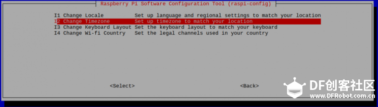 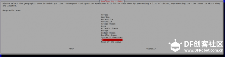 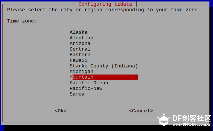 指令输入之后会转到一个选择时间域的程序,下移光标选择你所在的时区就可以了。原文链接: Mikey Sklar 指令输入之后会转到一个选择时间域的程序,下移光标选择你所在的时区就可以了。原文链接: Mikey Sklar |
dsweiliang 发表于 2016-4-22 08:36 https://mc.dfrobot.com.cn/thread-13396-1-1.html |


© 2013-2024 Comsenz Inc. Powered by Discuz! X3.4 Licensed


 置顶卡
置顶卡 变色卡
变色卡 千斤顶
千斤顶


 萌萌哒新人
萌萌哒新人
 活跃会员
活跃会员
 老版主限定
老版主限定
 小蘑菇
小蘑菇
 蘑菇人
蘑菇人


