|
8008| 1
|
情人节-Spreading Love With Robots |
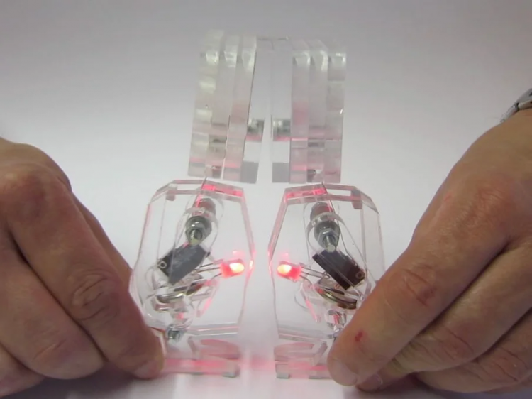 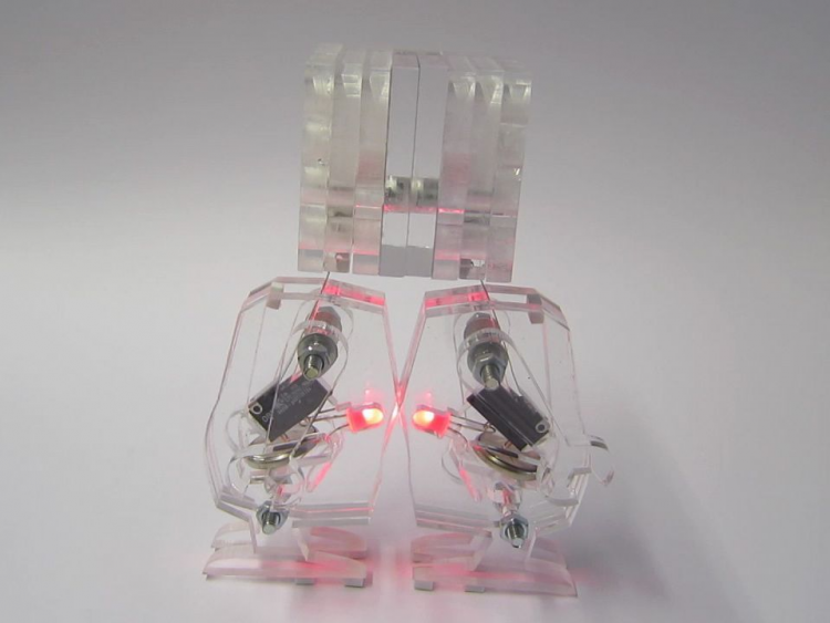 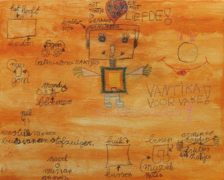 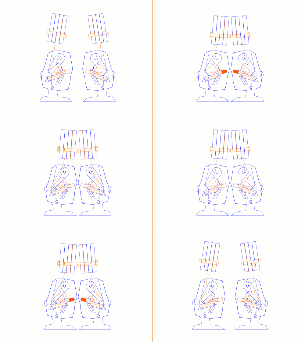 A building kit for love... The idea of a “Love Robot” was originally planted in my head by my daughter Tika’s work “A Robot made of Love and with Love”, as shown in the third picture below. So I started making little robots that are magnetically drawn to each other and when kissing, they show there love by lighting up their throbbing hart. My kissing robots described in “Give the Gift of Robot Love” were a big success. Such a success that I soon game to the conclusion that preparing the kit as a gift takes a lot of work. I don’t mind putting effort in making a gift for my friends, but I took just too much time to be able to spread my love to more people. Therefore, I decided to design a new version were the kit only needs laser cutting parts and gathering available components. At the same time I tried to simplify the assembly by the recipient. People being less handy doesn’t t mean I love them any less ;-) Waiting for the parts to arrive I made a simple animated GIF (fourth image below). It gave an idea of to the real thing. Obviously, with the parts available, I was able to test and do some fine tuning (as will be explained in the following steps). Check out the result in this video: The kit is assembled without any tools. How to assemble is described from step 4 on, but first I explain how I came to design. The main aspect of the design is a solder free concept. I realise soldering would give a more reliable electrical contacts possible, but then I considered that true love should allow for sorting out a broken contact once in a while :-) Another part of the concept is using (ID) photos as a face, allowing for a very simple way to personalise each robot. If you like this Ible, please give it your vote. 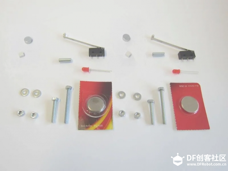 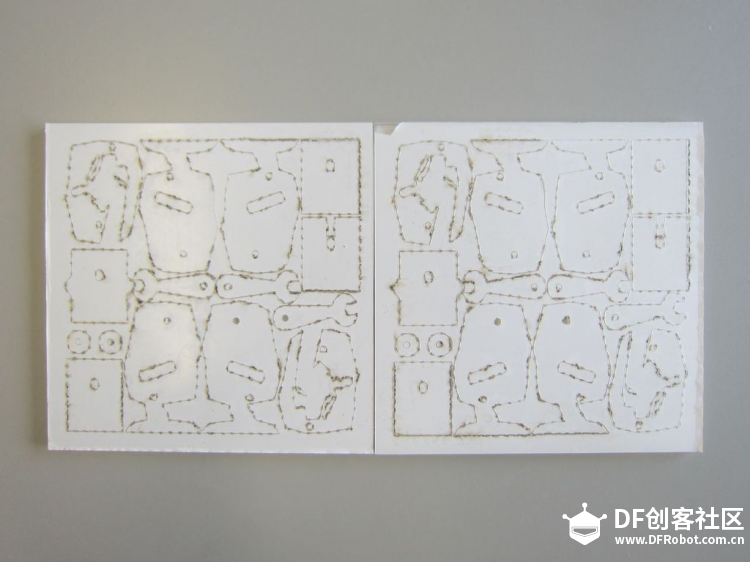 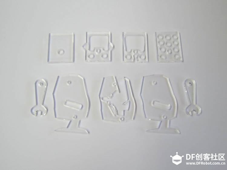 2 blinking LEDs (red being the colour of love) operating on 3V. Some blinking LEDs are clearly underpowered on 3V. The ones from Opitec (n° 236135) work great. 2 SPDT switches with a long lever. I use the cheapest available at Conrad (n° 703673-8A). They come with a wheel at the end of the lever, which is not used as wheel, but helps keeping the lever end in the head construction. 2 button cell batteries, 3V each. I use two CR 2032 for my design. Other batteries with other dimensions would need an adaptation of the design of the part holding the battery. 2 bolts M4 x 35 mm, 2 bolts M4 x 20 mm and 4 nuts M4. 4 washers fitting M4 bolts. 2 neodymium magnets 5 mm diameter X 15 mm length (The design can be adapted to more common magnet sizes like the ones available from Opitec) 2 neodymium magnets 8 mm diameter X 4 mm thickness (e.g. n°208305 at Opitec) 2 pieces of foam tape, 3 mm thick, about 5 x 5 mm 6 mm clear acrylic sheet (laser cut). I choose 6mm because the common SPTD switch is 6.5 mm thick, so it will be firmly held in the layered build up. You need clear or translucent acrylic sheet to have the LED shine through. The design for the laser cutting is provided below. I made it in Inkscape. The design gives the parts for one robot only. I couldn't fit two on a Pponoko P1 sheet. I was planning on adapting the design to fit two robots one P1 sheet, but instead I am thinking of making the robots slightly taller, and changing the proportions to bring the LED closer to where the human heart is. Apart from a laser cutter or laser cutting service, there are no tools required. Step 2: The Switch As Backbone 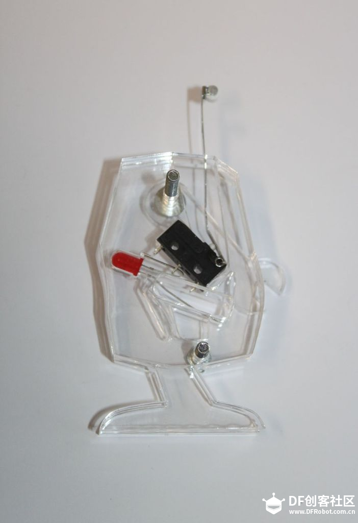 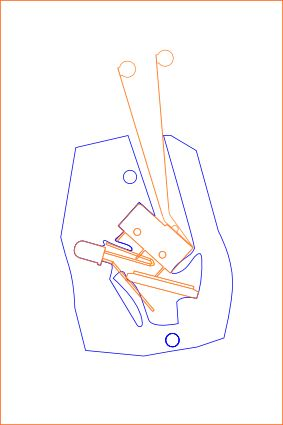 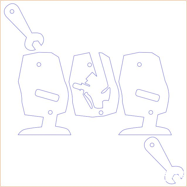 I choose to use a existing SPDT switch and build arround that (an alternative would have been to build a switch mechanism out of the acrylic sheet and bolts used as axles). To activate a common SPDTswitch with the robot’s magnetic attraction a large lever is needed. Large lever means large movement so I set out to integrate the switch and lever in the main “kissing” movement and have the it serve as backbone/neck. To eliminate any soldering, the mission was to integrate the switch, LED and battery in the robot’s trunk. The mounting holes in the switch are only 2.5 mm. As long bolts with that diameter are not very common, I choose not to use these holes to keep the switch in place in the layered structure. Instead I used the freedom of shape and accuracy laser cutting offers and designed a shape firmly holding the switch. I measured the switch and drew out the shape. As simple first approximation I did not take in account any clearance. Or actually by just drawing the switch as measured, half of the width of the laser cut (0,1 mm) serves as clearance. Next step was to keep the battery pressed against one of the legs of the switch, by designing a “spring” based on a narrow cut out. I experimented with a piece of acrylic sheet, cut with a hacksaw. The effectiveness and durability is something that needs to be checked in practice, but I got a good impression from the laser cut parts. I took the thickness of the battery from a data sheet, as using my metal calliper would have short circuited the battery (3.2 mm for a CR2032). To put tension on the spring I subtracted 1 mm from that thickness when making the laser cut design template. Next came the challenge to connect the LED without soldering. First the cut-out for the LED takes in account the flattened side on its rim, so it can be put in only one way and the polarity should always come out right when assembling. One of the LEDs legs (the -) goes through the hole in the middle leg of the switch and is held in place by the shape of the cut out. The other leg (+) is pressed against the side of the battery. This leg is bent downwards towards the “spring” holding the battery. The middle part holding the switch, LED and battery is clamped between two “leg” parts, with the three layers bolted together v(with paper as spacers). The side parts are slotted to give room to the battery, and allow replacing it without disassembling. The arms are added to the top bolts. For the last nut an arm already attached to the other robot can be used. The movement of the lever was checked on a "cross section" drawing of the two robots kissing. When the parts arrived some fine tuning was needed. First the angle of the body leaning forward was changed to get the heads close enough for the magnets to work. If you take a close look to the video in the intro you can notice the feet were sanded, and some foam tape pads were added to add som hight again (trial and error). Also a piece of foam tape was added to stop the lever and head to move back to far. Pictures will follow. The end result is already implemented in the laser cut design attached to Step 1 of this Ible. Step 3: The Head 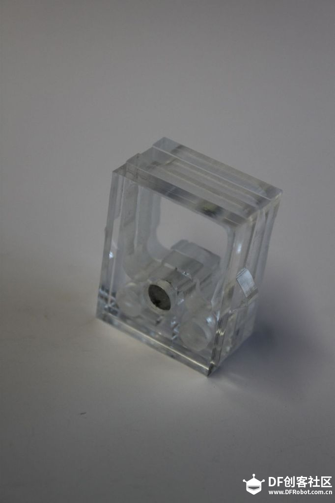 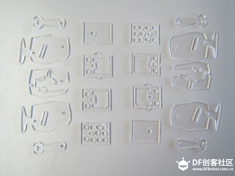 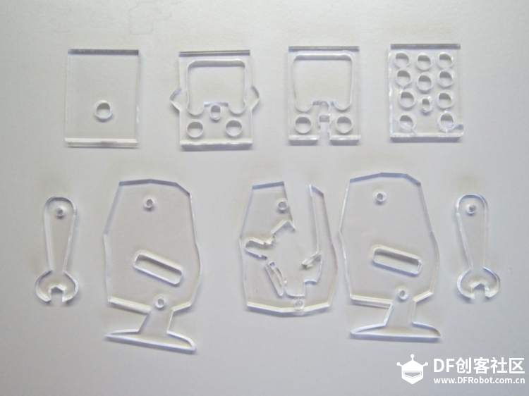  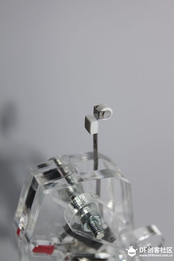 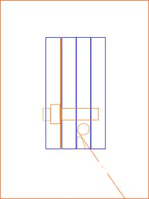 As an alternative to drawing a face I came up to use ID photos of the recipients and integrate them in a layered head construction. I first thought of a bolt going through the layered construction. But then I decided to give the “kissing” magnets a second function: it also keeps the head together. This way there is no need to make a hole in the photo. The trick is that the mouth magnet does not come to the front layer, so the faces still separate when the robots are pulled away from each other, while the head keeps together. I tested with one magnet and a bolt for each head, but I could make it strong enough that way. When testing, it quickly became clear the head was far too heavy. So I made large cut outs in al parts but the face layer. I did this by drilling and sanding with a power file, but again I implemented this in the laser cut desing attached to Step 1 of this Ible. I also added some foam tape where the lever goes into the head, as this proved to be necessary to keep head leaning backwards for a consistent switching of after the kiss. I could not solve this by changing the layer design, so it will be included in the final assembly instructions. Step 4: Assembly Part 1: Preparing the Parts 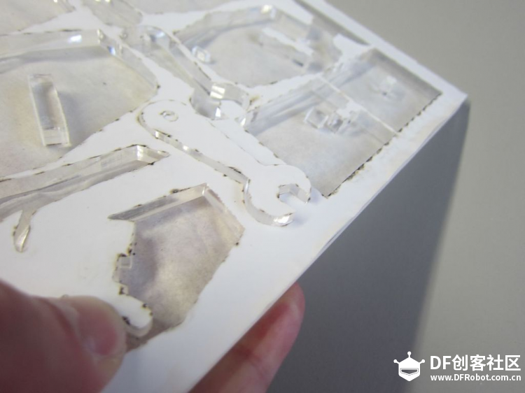 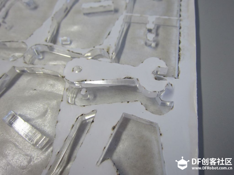 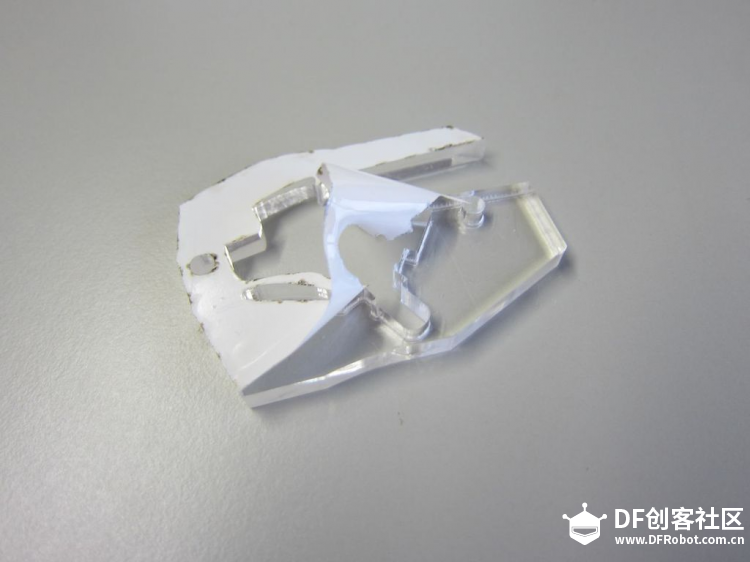 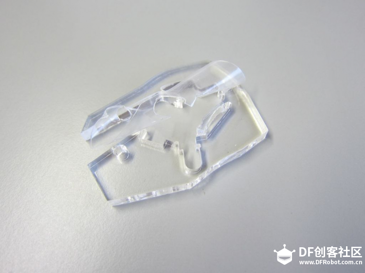 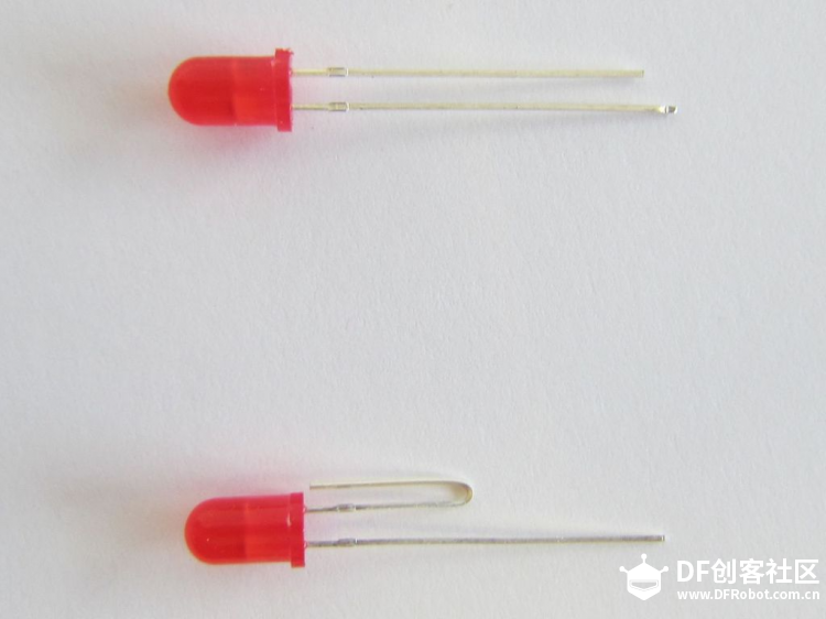 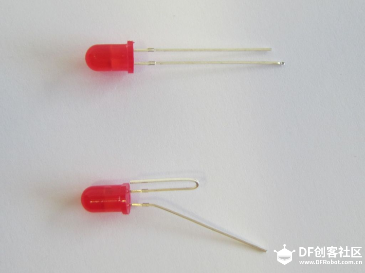 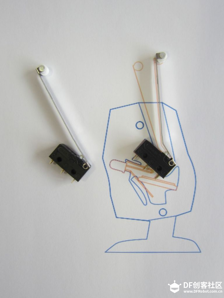 Remove all parts from the paper and peel of the protective film from both sides. The switch arm needs to be bent using a printout a reference. The shortest leg (- leg) of the LED is folded in two. The longest leg (+ leg) of the LED gets a slight bend near the body of the LED. This bend is not critical; it will take its final shape when the battery is fitted. Step 5: Assembly Part 2: the Body  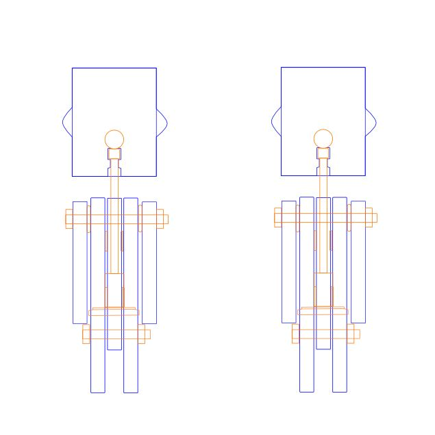 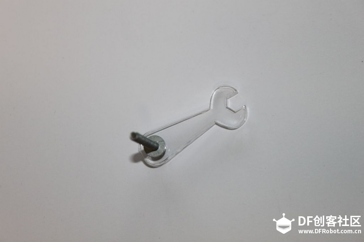 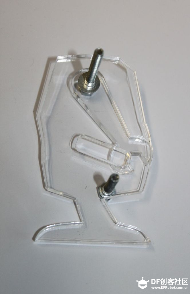  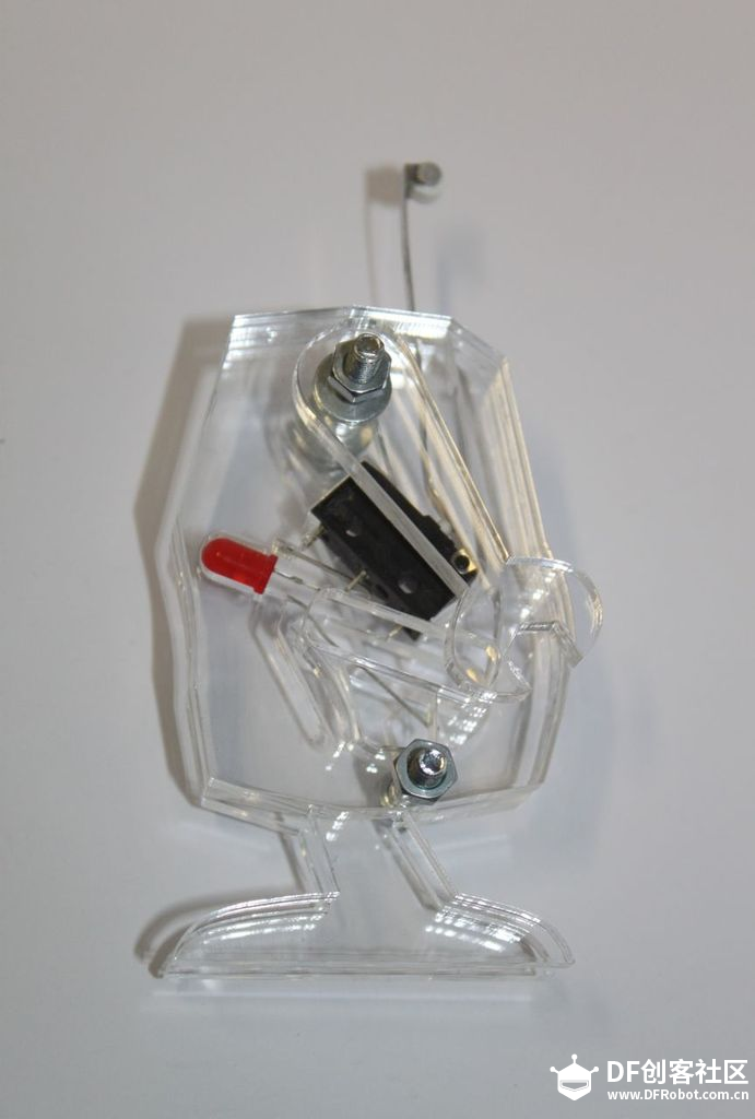 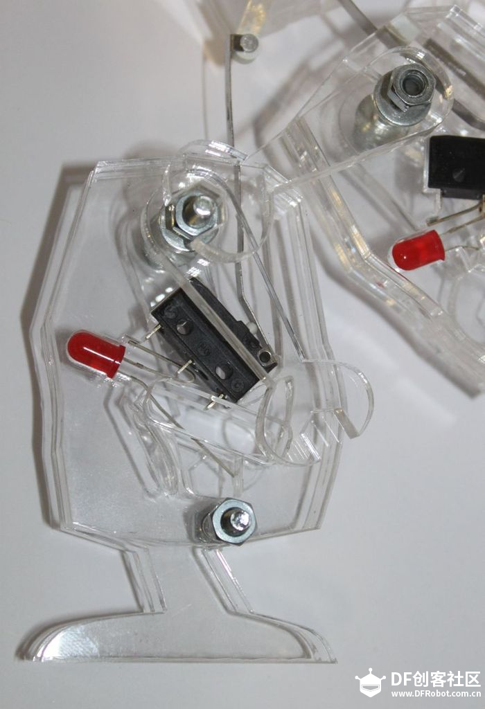  The body is built up in layers. You start by putting a long bolt through one of the arms. Next comes a washer. Then you put on a body side with a foot and run through a 25 mm bolt from the underside. Put the short LED leg through the middle contact of the switch. Click the LED and the switch in the body part with the large cut-out. The LED's rim has a flattened side, which should slide in the cut-out, preventing the LED from rotating. The switch is clamped in the cut-out, so it can take a little force to fit it in. Add another body side with a foot, a washer and the second arm. Close up with nuts and tighten them with an arm of the other robot. Keep at least one arm to the sides of the battery opening, keeping the "battery compartment" accessible. Slide in the battery with the + side down (towards the feet), until it comes out a couple of mm on each side of the robot body. While doing this it should push down the "spring" cut out of the acrylic sheet. This "spring" should push the long leg of the LED to the + side of the battery and the - side of the battery against the bottom contact of the switch. Move the lever of the switch forward to test. Step 6: Assembly Part 3: the Head 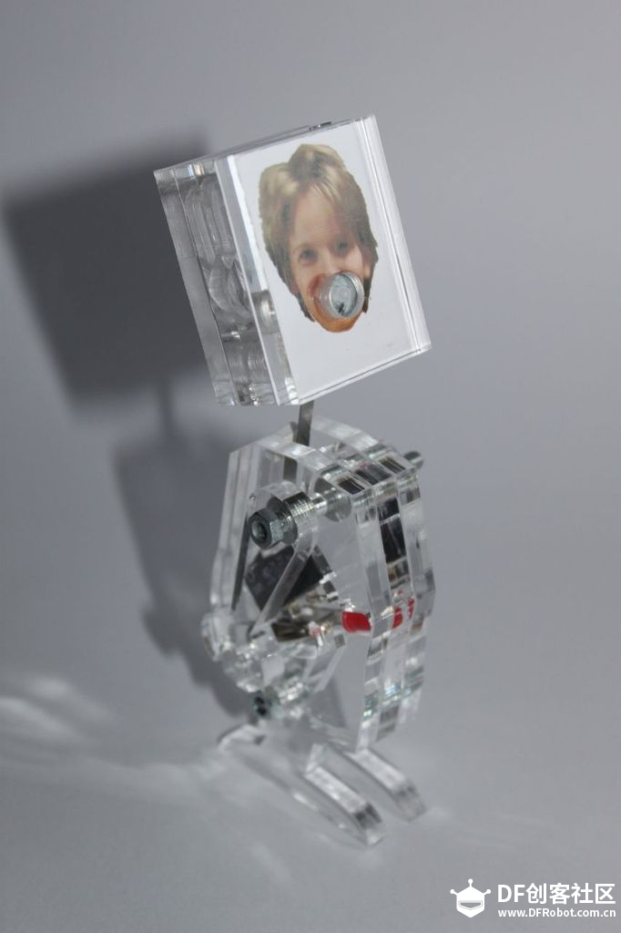  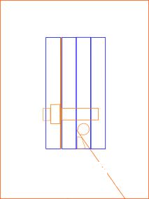 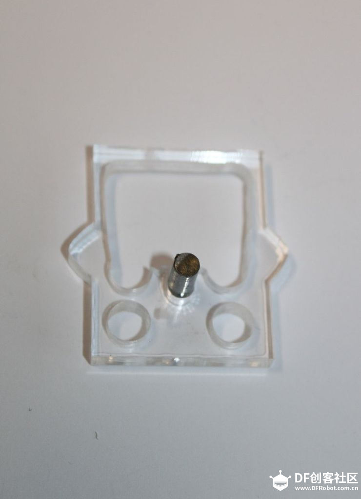 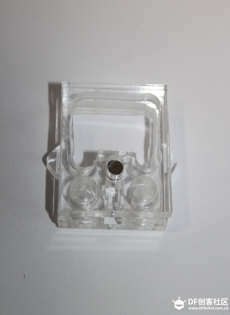 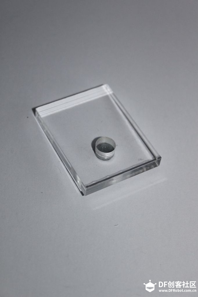 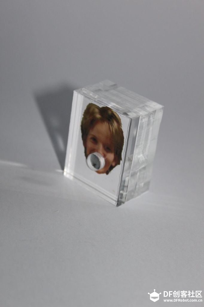 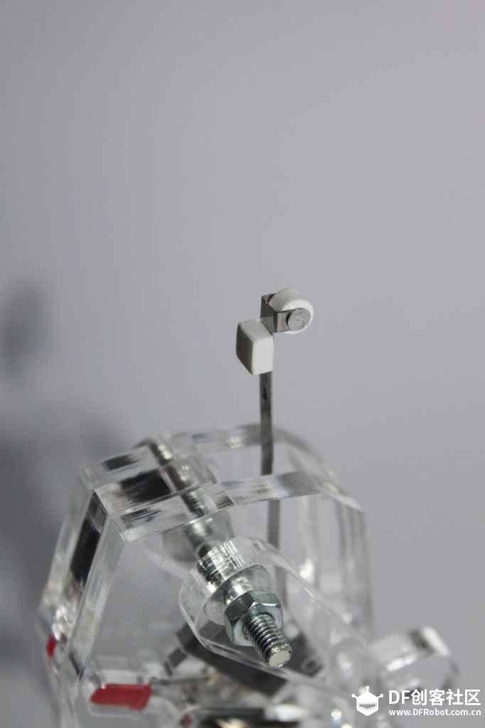 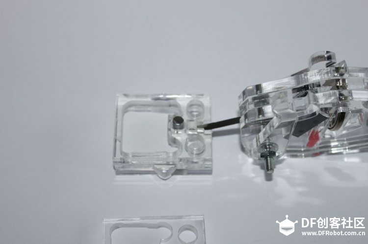 The head is a layered construction too, but with layers at 90° of the body. The head is assembled and put on the robot afterwards. First the three layers with the large cut-outs are slid on the long magnet. The photos show pieces somewhat different from the final kit, as at that time they were adapted by hand. Put a long magnet in the part with the ears, making sure it is flush with one side by pressing it against a hard surface (e.g. a table top). Next put on the part with the cut-out for the lever end. On top comes one more layer, one without “ears”. Put a disc magnet in the face layer and test what sided is attracted to the head assembly. Push the "mouth" magnet as deep in the face as you can. Put on an ID photo (45 by 35 mm standard size) between the face layer and the rest of the head. To mount the head on thze robot the back layer is temporarily removed. Put a small piece of foam tape on the lever as shown. Put the lever in the cut-out and add the back layer again. The layers should be tight together and the head leaning backwards. The robot is ready. When you have made both, but they do not want to kiss each other, reverse both the magnets in one of them. If only love were that easy... 作者: masynmachien |
 萌萌哒新人
萌萌哒新人
 志“童”道合
 沪公网安备31011502402448
© 2013-2026 Comsenz Inc. Powered by Discuz! X3.4 Licensed