本帖最后由 glwz007 于 2023-5-30 22:20 编辑 前言 一、项目由来 我是一个物理老师,也是一个喜欢折腾实验的老师,在信息化数字化的浪潮下,一直有一个想法,就是将传统的物理实验信息化、数字化,在这方面我一直处于学习和不断的制作中。
在中学物理实验中,电学实验也是一个重点,而电学实验,离不开电学三个基本物理量电压、电流、电阻的测量,这次先从电压的测量工具电压表入手进行学习。
二、对电压表的对比分析 1. 传统的电压表
中学物理实验室传统的电压表都是电磁式电表,如下图所示:
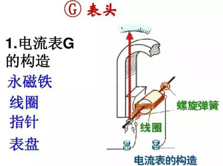
它是基于灵敏电流计G改装得到,下图是灵敏电流计G(俗称表头)的构造图,它的原理是利用通电线圈在磁场中受力转动,通过电流计的电流越大,与线圈相连接的指针转过的角度越大。
通过串并联电路,可以将表头改装为不同量程的电压表和电流表。
这种传统的电流表,属于模拟式电压表,优点是结构简单,价格便宜,测量频率范围较宽;缺点是精度、分辨力较低,不便于与计算机组成自动测试系统。
2.数字式电压表
数字是电压表用A/D转换器和数字显示器代替了模拟电压表的测量显示部分,优缺点基本上正好与模拟式电压表相反。
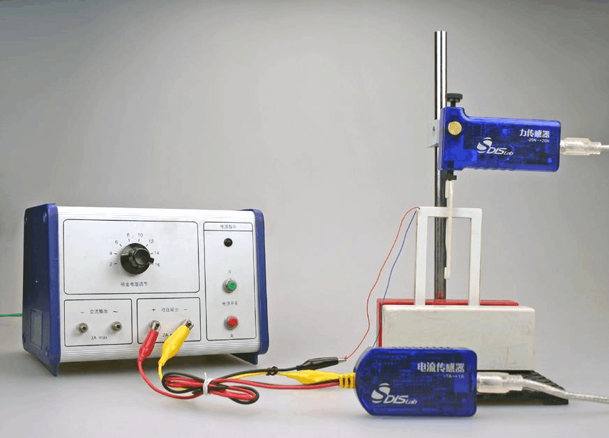
在中学实验室,常用的数字式电表,大多是商品化的DIS系统,DIS( Digital Information System) 实验技术,又称“数字化信息系统”,是由“传感器、数据采集器、实验软件包(教材专用软件、通用扩展软件)、计算机”等构成的新型实验系统。该系统成功地克服了传统物理实验仪器的诸多弊端,有力地支持了信息技术与物理教学的全面整合。
但是这种系统价格相对比较高,于是我萌生了自制数字电压表的想法,下面是初步的实验过程。
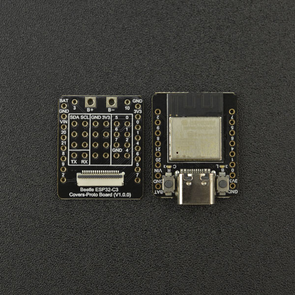
三、基于Beetle ESP32-C3 + ADS1115的数字电压表 前段时间,DFRobot论坛开展了Beetle ESP32-C3的免费试用活动,于是我申请了两块作为实验用主控板,在此向DFRobot表示衷心的感谢!
(一)主要硬件
本次使用的主要元件如下:
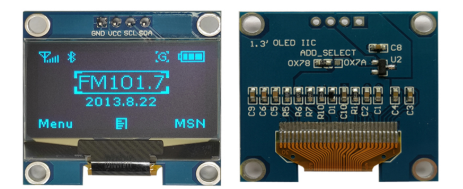
2.显示屏采用12864OLED,OLED 屏幕作为一种新型的显示技术,其自身可以发光,亮度,对比度高,功耗低,在当下备受追捧。而在我们正常的显示调整参数过程中,我们越来越多的使用这种屏幕。我们使用的一般是分辨率为 128x64 ,屏幕尺寸为 0.96 寸。
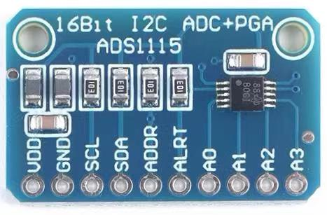
3.AD转换器采用ADS1115,ADS1115是一种精密16位模数转换器(ADC),能将模拟信号转换为数字信号。它采用I2C接口进行通信,并具有四个单端或两个差分输入通道。由于其高精度和低功耗特性,ADS1115广泛用于温度、压力、湿度等传感器的数据采集与处理。
(二)编程软件
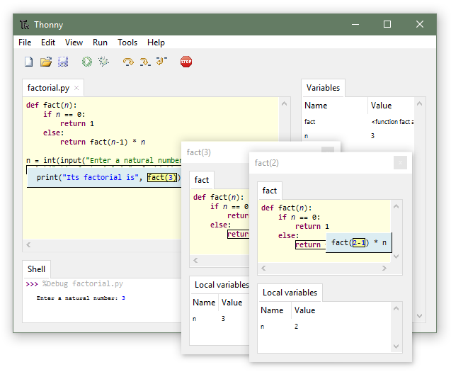
在以往的制作中,我大多数情况下采用图形化编程模式,这次转换使用代码编程。采用MicroPython,编辑器为Thonny。Thonny 是一个面向初学者的 Python IDE
Thonny 由爱沙尼亚的 Tartu 大学开发,它采用了不同的方法,因为它的调试器是专为学习和教学编程而设计的。
(三)制作过程
1. 硬件搭建
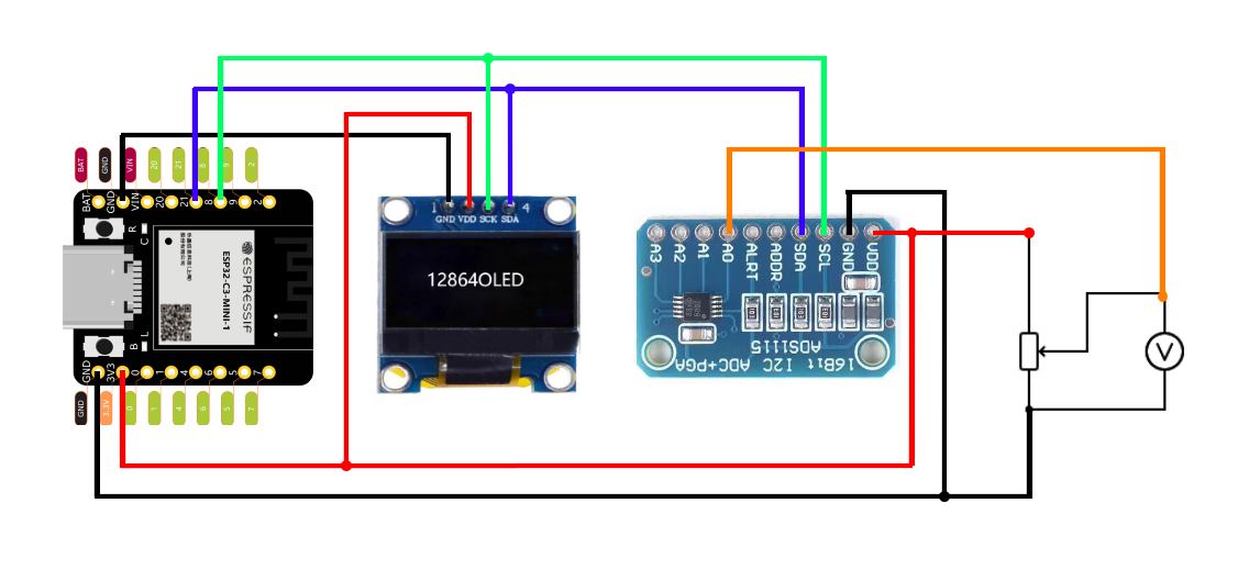
将Beetle ESP32-C3、12864OLED屏、ADS1115通过连接线连接到面包板上,为了改变测量电压,还接了一个1KΩ的电位器,将电位器可变电压提供给自制电压表和数字万用表测量作为对比。连接示意图如下:
2. 软件编程
(2)编程环境配置
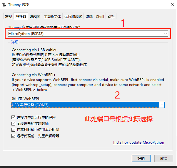
刷好固件后,启动Thonny,选择“运行”菜单,进行如下图配置:
点击“视图”菜单中“文件”选项,如果前面配置正常,将会显示主控板中文件,一开始应该是空的。
(3)新建”ssd1306.py”,复制下面代码,保存到“MicroPython设备”作为12864OLED显示屏的库。
#MicroPython SSD1306 OLED driver, I2C and SPI interfaces created by Adafruit
import time
import framebuf
# register definitions
SET_CONTRAST = const(0x81)
SET_ENTIRE_ON = const(0xa4)
SET_NORM_INV = const(0xa6)
SET_DISP = const(0xae)
SET_MEM_ADDR = const(0x20)
SET_COL_ADDR = const(0x21)
SET_PAGE_ADDR = const(0x22)
SET_DISP_START_LINE = const(0x40)
SET_SEG_REMAP = const(0xa0)
SET_MUX_RATIO = const(0xa8)
SET_COM_OUT_DIR = const(0xc0)
SET_DISP_OFFSET = const(0xd3)
SET_COM_PIN_CFG = const(0xda)
SET_DISP_CLK_DIV = const(0xd5)
SET_PRECHARGE = const(0xd9)
SET_VCOM_DESEL = const(0xdb)
SET_CHARGE_PUMP = const(0x8d)
class SSD1306:
def __init__(self, width, height, external_vcc):
self.width = width
self.height = height
self.external_vcc = external_vcc
self.pages = self.height // 8
# Note the subclass must initialize self.framebuf to a framebuffer.
# This is necessary because the underlying data buffer is different
# between I2C and SPI implementations (I2C needs an extra byte).
self.poweron()
self.init_display()
def init_display(self):
for cmd in (
SET_DISP | 0x00, # off
# address setting
SET_MEM_ADDR, 0x00, # horizontal
# resolution and layout
SET_DISP_START_LINE | 0x00,
SET_SEG_REMAP | 0x01, # column addr 127 mapped to SEG0
SET_MUX_RATIO, self.height - 1,
SET_COM_OUT_DIR | 0x08, # scan from COM[N] to COM0
SET_DISP_OFFSET, 0x00,
SET_COM_PIN_CFG, 0x02 if self.height == 32 else 0x12,
# timing and driving scheme
SET_DISP_CLK_DIV, 0x80,
SET_PRECHARGE, 0x22 if self.external_vcc else 0xf1,
SET_VCOM_DESEL, 0x30, # 0.83*Vcc
# display
SET_CONTRAST, 0xff, # maximum
SET_ENTIRE_ON, # output follows RAM contents
SET_NORM_INV, # not inverted
# charge pump
SET_CHARGE_PUMP, 0x10 if self.external_vcc else 0x14,
SET_DISP | 0x01): # on
self.write_cmd(cmd)
self.fill(0)
self.show()
def poweroff(self):
self.write_cmd(SET_DISP | 0x00)
def contrast(self, contrast):
self.write_cmd(SET_CONTRAST)
self.write_cmd(contrast)
def invert(self, invert):
self.write_cmd(SET_NORM_INV | (invert & 1))
def show(self):
x0 = 0
x1 = self.width - 1
if self.width == 64:
# displays with width of 64 pixels are shifted by 32
x0 += 32
x1 += 32
self.write_cmd(SET_COL_ADDR)
self.write_cmd(x0)
self.write_cmd(x1)
self.write_cmd(SET_PAGE_ADDR)
self.write_cmd(0)
self.write_cmd(self.pages - 1)
self.write_framebuf()
def fill(self, col):
self.framebuf.fill(col)
def pixel(self, x, y, col):
self.framebuf.pixel(x, y, col)
def scroll(self, dx, dy):
self.framebuf.scroll(dx, dy)
def text(self, string, x, y, col=1):
self.framebuf.text(string, x, y, col)
class SSD1306_I2C(SSD1306):
def __init__(self, width, height, i2c, addr=0x3c, external_vcc=False):
self.i2c = i2c
self.addr = addr
self.temp = bytearray(2)
# Add an extra byte to the data buffer to hold an I2C data/command byte
# to use hardware-compatible I2C transactions. A memoryview of the
# buffer is used to mask this byte from the framebuffer operations
# (without a major memory hit as memoryview doesn't copy to a separate
# buffer).
self.buffer = bytearray(((height // 8) * width) + 1)
self.buffer[0] = 0x40 # Set first byte of data buffer to Co=0, D/C=1
self.framebuf = framebuf.FrameBuffer1(memoryview(self.buffer)[1:], width, height)
super().__init__(width, height, external_vcc)
def write_cmd(self, cmd):
self.temp[0] = 0x80 # Co=1, D/C#=0
self.temp[1] = cmd
self.i2c.writeto(self.addr, self.temp)
def write_framebuf(self):
# Blast out the frame buffer using a single I2C transaction to support
# hardware I2C interfaces.
self.i2c.writeto(self.addr, self.buffer)
def poweron(self):
pass
class SSD1306_SPI(SSD1306):
def __init__(self, width, height, spi, dc, res, cs, external_vcc=False):
self.rate = 10 * 1024 * 1024
dc.init(dc.OUT, value=0)
res.init(res.OUT, value=0)
cs.init(cs.OUT, value=1)
self.spi = spi
self.dc = dc
self.res = res
self.cs = cs
self.buffer = bytearray((height // 8) * width)
self.framebuf = framebuf.FrameBuffer1(self.buffer, width, height)
super().__init__(width, height, external_vcc)
def write_cmd(self, cmd):
self.spi.init(baudrate=self.rate, polarity=0, phase=0)
self.cs.high()
self.dc.low()
self.cs.low()
self.spi.write(bytearray([cmd]))
self.cs.high()
def write_framebuf(self):
self.spi.init(baudrate=self.rate, polarity=0, phase=0)
self.cs.high()
self.dc.high()
self.cs.low()
self.spi.write(self.buffer)
self.cs.high()
def poweron(self):
self.res.high()
time.sleep_ms(1)
self.res.low()
time.sleep_ms(10)
self.res.high() 复制代码 新建”ads1x15.py”,复制下面代码,保存到“MicroPython设备”作为ADS1115的库。
# The MIT License (MIT)
#
# Copyright (c) 2016 Radomir Dopieralski (@deshipu),
# 2017 Robert Hammelrath (@robert-hh)
#
# Permission is hereby granted, free of charge, to any person obtaining a copy
# of this software and associated documentation files (the "Software"), to deal
# in the Software without restriction, including without limitation the rights
# to use, copy, modify, merge, publish, distribute, sublicense, and/or sell
# copies of the Software, and to permit persons to whom the Software is
# furnished to do so, subject to the following conditions:
#
# The above copyright notice and this permission notice shall be included in
# all copies or substantial portions of the Software.
#
# THE SOFTWARE IS PROVIDED "AS IS", WITHOUT WARRANTY OF ANY KIND, EXPRESS OR
# IMPLIED, INCLUDING BUT NOT LIMITED TO THE WARRANTIES OF MERCHANTABILITY,
# FITNESS FOR A PARTICULAR PURPOSE AND NONINFRINGEMENT. IN NO EVENT SHALL THE
# AUTHORS OR COPYRIGHT HOLDERS BE LIABLE FOR ANY CLAIM, DAMAGES OR OTHER
# LIABILITY, WHETHER IN AN ACTION OF CONTRACT, TORT OR OTHERWISE, ARISING FROM,
# OUT OF OR IN CONNECTION WITH THE SOFTWARE OR THE USE OR OTHER DEALINGS IN
# THE SOFTWARE.
#
import utime as time
_REGISTER_MASK = const(0x03)
_REGISTER_CONVERT = const(0x00)
_REGISTER_CONFIG = const(0x01)
_REGISTER_LOWTHRESH = const(0x02)
_REGISTER_HITHRESH = const(0x03)
_OS_MASK = const(0x8000)
_OS_SINGLE = const(0x8000) # Write: Set to start a single-conversion
_OS_BUSY = const(0x0000) # Read: Bit=0 when conversion is in progress
_OS_NOTBUSY = const(0x8000) # Read: Bit=1 when no conversion is in progress
_MUX_MASK = const(0x7000)
_MUX_DIFF_0_1 = const(0x0000) # Differential P = AIN0, N = AIN1 (default)
_MUX_DIFF_0_3 = const(0x1000) # Differential P = AIN0, N = AIN3
_MUX_DIFF_1_3 = const(0x2000) # Differential P = AIN1, N = AIN3
_MUX_DIFF_2_3 = const(0x3000) # Differential P = AIN2, N = AIN3
_MUX_SINGLE_0 = const(0x4000) # Single-ended AIN0
_MUX_SINGLE_1 = const(0x5000) # Single-ended AIN1
_MUX_SINGLE_2 = const(0x6000) # Single-ended AIN2
_MUX_SINGLE_3 = const(0x7000) # Single-ended AIN3
_PGA_MASK = const(0x0E00)
_PGA_6_144V = const(0x0000) # +/-6.144V range = Gain 2/3
_PGA_4_096V = const(0x0200) # +/-4.096V range = Gain 1
_PGA_2_048V = const(0x0400) # +/-2.048V range = Gain 2 (default)
_PGA_1_024V = const(0x0600) # +/-1.024V range = Gain 4
_PGA_0_512V = const(0x0800) # +/-0.512V range = Gain 8
_PGA_0_256V = const(0x0A00) # +/-0.256V range = Gain 16
_MODE_MASK = const(0x0100)
_MODE_CONTIN = const(0x0000) # Continuous conversion mode
_MODE_SINGLE = const(0x0100) # Power-down single-shot mode (default)
_DR_MASK = const(0x00E0) # Values ADS1015/ADS1115
_DR_128SPS = const(0x0000) # 128 /8 samples per second
_DR_250SPS = const(0x0020) # 250 /16 samples per second
_DR_490SPS = const(0x0040) # 490 /32 samples per second
_DR_920SPS = const(0x0060) # 920 /64 samples per second
_DR_1600SPS = const(0x0080) # 1600/128 samples per second (default)
_DR_2400SPS = const(0x00A0) # 2400/250 samples per second
_DR_3300SPS = const(0x00C0) # 3300/475 samples per second
_DR_860SPS = const(0x00E0) # - /860 samples per Second
_CMODE_MASK = const(0x0010)
_CMODE_TRAD = const(0x0000) # Traditional comparator with hysteresis (default)
_CMODE_WINDOW = const(0x0010) # Window comparator
_CPOL_MASK = const(0x0008)
_CPOL_ACTVLOW = const(0x0000) # ALERT/RDY pin is low when active (default)
_CPOL_ACTVHI = const(0x0008) # ALERT/RDY pin is high when active
_CLAT_MASK = const(0x0004) # Determines if ALERT/RDY pin latches once asserted
_CLAT_NONLAT = const(0x0000) # Non-latching comparator (default)
_CLAT_LATCH = const(0x0004) # Latching comparator
_CQUE_MASK = const(0x0003)
_CQUE_1CONV = const(0x0000) # Assert ALERT/RDY after one conversions
_CQUE_2CONV = const(0x0001) # Assert ALERT/RDY after two conversions
_CQUE_4CONV = const(0x0002) # Assert ALERT/RDY after four conversions
# Disable the comparator and put ALERT/RDY in high state (default)
_CQUE_NONE = const(0x0003)
_GAINS = (
_PGA_6_144V, # 2/3x
_PGA_4_096V, # 1x
_PGA_2_048V, # 2x
_PGA_1_024V, # 4x
_PGA_0_512V, # 8x
_PGA_0_256V # 16x
)
_GAINS_V = (
6.144, # 2/3x
4.096, # 1x
2.048, # 2x
1.024, # 4x
0.512, # 8x
0.256 # 16x
)
_CHANNELS = {
(0, None): _MUX_SINGLE_0,
(1, None): _MUX_SINGLE_1,
(2, None): _MUX_SINGLE_2,
(3, None): _MUX_SINGLE_3,
(0, 1): _MUX_DIFF_0_1,
(0, 3): _MUX_DIFF_0_3,
(1, 3): _MUX_DIFF_1_3,
(2, 3): _MUX_DIFF_2_3,
}
_RATES = (
_DR_128SPS, # 128/8 samples per second
_DR_250SPS, # 250/16 samples per second
_DR_490SPS, # 490/32 samples per second
_DR_920SPS, # 920/64 samples per second
_DR_1600SPS, # 1600/128 samples per second (default)
_DR_2400SPS, # 2400/250 samples per second
_DR_3300SPS, # 3300/475 samples per second
_DR_860SPS # - /860 samples per Second
)
class ADS1115:
def __init__(self, i2c, address=0x48, gain=1):
self.i2c = i2c
self.address = address
self.gain = gain
self.temp2 = bytearray(2)
def _write_register(self, register, value):
self.temp2[0] = value >> 8
self.temp2[1] = value & 0xff
self.i2c.writeto_mem(self.address, register, self.temp2)
def _read_register(self, register):
self.i2c.readfrom_mem_into(self.address, register, self.temp2)
return (self.temp2[0] << 8) | self.temp2[1]
def raw_to_v(self, raw):
v_p_b = _GAINS_V[self.gain] / 32767
return raw * v_p_b
def set_conv(self, rate=4, channel1=0, channel2=None):
"""Set mode for read_rev"""
self.mode = (_CQUE_NONE | _CLAT_NONLAT |
_CPOL_ACTVLOW | _CMODE_TRAD | _RATES[rate] |
_MODE_SINGLE | _OS_SINGLE | _GAINS[self.gain] |
_CHANNELS[(channel1, channel2)])
def read(self, rate=4, channel1=0, channel2=None):
"""Read voltage between a channel and GND.
Time depends on conversion rate."""
self._write_register(_REGISTER_CONFIG, (_CQUE_NONE | _CLAT_NONLAT |
_CPOL_ACTVLOW | _CMODE_TRAD | _RATES[rate] |
_MODE_SINGLE | _OS_SINGLE | _GAINS[self.gain] |
_CHANNELS[(channel1, channel2)]))
while not self._read_register(_REGISTER_CONFIG) & _OS_NOTBUSY:
time.sleep_ms(1)
res = self._read_register(_REGISTER_CONVERT)
return res if res < 32768 else res - 65536
def read_rev(self):
"""Read voltage between a channel and GND. and then start
the next conversion."""
res = self._read_register(_REGISTER_CONVERT)
self._write_register(_REGISTER_CONFIG, self.mode)
return res if res < 32768 else res - 65536
def alert_start(self, rate=4, channel1=0, channel2=None,
threshold_high=0x4000, threshold_low=0, latched=False) :
"""Start continuous measurement, set ALERT pin on threshold."""
self._write_register(_REGISTER_LOWTHRESH, threshold_low)
self._write_register(_REGISTER_HITHRESH, threshold_high)
self._write_register(_REGISTER_CONFIG, _CQUE_1CONV |
_CLAT_LATCH if latched else _CLAT_NONLAT |
_CPOL_ACTVLOW | _CMODE_TRAD | _RATES[rate] |
_MODE_CONTIN | _GAINS[self.gain] |
_CHANNELS[(channel1, channel2)])
def conversion_start(self, rate=4, channel1=0, channel2=None):
"""Start continuous measurement, trigger on ALERT/RDY pin."""
self._write_register(_REGISTER_LOWTHRESH, 0)
self._write_register(_REGISTER_HITHRESH, 0x8000)
self._write_register(_REGISTER_CONFIG, _CQUE_1CONV | _CLAT_NONLAT |
_CPOL_ACTVLOW | _CMODE_TRAD | _RATES[rate] |
_MODE_CONTIN | _GAINS[self.gain] |
_CHANNELS[(channel1, channel2)])
def alert_read(self):
"""Get the last reading from the continuous measurement."""
res = self._read_register(_REGISTER_CONVERT)
return res if res < 32768 else res - 65536
class ADS1113(ADS1115):
def __init__(self, i2c, address=0x48):
super().__init__(i2c, address, 1)
def raw_to_v(self, raw):
return super().raw_to_v(raw)
def read(self, rate=4):
return super().read(rate, 0, 1)
def alert_start(self, rate=4, threshold_high=0x4000, threshold_low=0, latched=False):
return super().alert_start(rate, 0, 1, threshold_high, threshold_low, latched)
def alert_read(self):
return super().alert_read()
class ADS1114(ADS1115):
def __init__(self, i2c, address=0x48, gain=1):
super().__init__(i2c, address, gain)
def raw_to_v(self, raw):
return super().raw_to_v(raw)
def read(self, rate=4):
return super().read(rate, 0, 1)
def alert_start(self, rate=4, threshold_high=0x4000, threshold_low=0, latched=False):
return super().alert_start(rate, 0, 1, threshold_high,
threshold_low, latched)
def alert_read(self):
return super().alert_read()
class ADS1015(ADS1115):
def __init__(self, i2c, address=0x48, gain=1):
super().__init__(i2c, address, gain)
def raw_to_v(self, raw):
return super().raw_to_v(raw << 4)
def read(self, rate=4, channel1=0, channel2=None):
return super().read(rate, channel1, channel2) >> 4
def alert_start(self, rate=4, channel1=0, channel2=None, threshold_high=0x400,
threshold_low=0, latched=False):
return super().alert_start(rate, channel1, channel2, threshold_high << 4,
threshold_low << 4, latched)
def alert_read(self):
return super().alert_read() >> 4 复制代码 新建”main.py”,复制下面代码,作为主程序,主控板启动会自动执行这个程序。
# 使用ADS1115测量电压,并用OLED屏幕显示
import ads1x15 ,time
from machine import Pin, SoftI2C
import ssd1306
import time
i2c = SoftI2C(scl=Pin(9), sda=Pin(8),freq=400000)
oled = ssd1306.SSD1306_I2C(128, 64 ,i2c)
adc = ads1x15.ADS1115(i2c)
# 汉字字典
character_dict = {
'电': [0x01,0x01,0x01,0x3F,0x21,0x21,0x21,0x3F,0x21,0x21,0x21,0x3F,0x21,0x01,0x01,0x00,
0x00,0x00,0x00,0xF8,0x08,0x08,0x08,0xF8,0x08,0x08,0x08,0xF8,0x0A,0x02,0x02,0xFE],
'压': [0x00,0x3F,0x20,0x20,0x20,0x20,0x20,0x2F,0x20,0x20,0x20,0x20,0x20,0x40,0x5F,0x80,
0x00,0xFE,0x00,0x80,0x80,0x80,0x80,0xFC,0x80,0x80,0x90,0x88,0x88,0x80,0xFE,0x00],
'流': [0x00,0x20,0x17,0x10,0x81,0x42,0x47,0x10,0x10,0x22,0xE2,0x22,0x22,0x22,0x24,0x08,
0x80,0x40,0xFE,0x80,0x10,0x08,0xFC,0x04,0x00,0x48,0x48,0x48,0x48,0x4A,0x4A,0x46],
'测': [0x00,0x27,0x14,0x14,0x85,0x45,0x45,0x15,0x15,0x25,0xE5,0x21,0x22,0x22,0x24,0x08,
0x04,0xC4,0x44,0x54,0x54,0x54,0x54,0x54,0x54,0x54,0x54,0x04,0x84,0x44,0x14,0x08],
'量': [0x00,0x1F,0x10,0x1F,0x10,0xFF,0x00,0x1F,0x11,0x1F,0x11,0x1F,0x01,0x1F,0x01,0x7F,
0x00,0xF0,0x10,0xF0,0x10,0xFE,0x00,0xF0,0x10,0xF0,0x10,0xF0,0x00,0xF0,0x00,0xFC],
'A': [0x00,0x00,0x00,0x10,0x10,0x18,0x28,0x28,0x24,0x3C,0x44,0x42,0x42,0xE7,0x00,0x00],
'V': [0x00,0x00,0x00,0xE7,0x42,0x42,0x44,0x24,0x24,0x28,0x28,0x18,0x10,0x10,0x00,0x00],
':': [0x00,0x00,0x00,0x00,0x00,0x00,0x18,0x18,0x00,0x00,0x00,0x00,0x18,0x18,0x00,0x00],
'-': [0x00,0x00,0x00,0x00,0x00,0x00,0x00,0x00,0x7E,0x00,0x00,0x00,0x00,0x00,0x00,0x00],
'.': [0x00,0x00,0x00,0x00,0x00,0x00,0x00,0x00,0x00,0x00,0x00,0x00,0x60,0x60,0x00,0x00],
'0': [0x00,0x00,0x00,0x18,0x24,0x42,0x42,0x42,0x42,0x42,0x42,0x42,0x24,0x18,0x00,0x00],
'1': [0x00,0x00,0x00,0x08,0x38,0x08,0x08,0x08,0x08,0x08,0x08,0x08,0x08,0x3E,0x00,0x00],
'2': [0x00,0x00,0x00,0x3C,0x42,0x42,0x42,0x02,0x04,0x08,0x10,0x20,0x42,0x7E,0x00,0x00],
'3': [0x00,0x00,0x00,0x3C,0x42,0x42,0x02,0x04,0x18,0x04,0x02,0x42,0x42,0x3C,0x00,0x00],
'4': [0x00,0x00,0x00,0x04,0x0C,0x0C,0x14,0x24,0x24,0x44,0x7F,0x04,0x04,0x1F,0x00,0x00],
'5': [0x00,0x00,0x00,0x7E,0x40,0x40,0x40,0x78,0x44,0x02,0x02,0x42,0x44,0x38,0x00,0x00],
'6': [0x00,0x00,0x00,0x18,0x24,0x40,0x40,0x5C,0x62,0x42,0x42,0x42,0x22,0x1C,0x00,0x00],
'7': [0x00,0x00,0x00,0x7E,0x42,0x04,0x04,0x08,0x08,0x10,0x10,0x10,0x10,0x10,0x00,0x00],
'8': [0x00,0x00,0x00,0x3C,0x42,0x42,0x42,0x24,0x18,0x24,0x42,0x42,0x42,0x3C,0x00,0x00],
'9': [0x00,0x00,0x00,0x38,0x44,0x42,0x42,0x42,0x46,0x3A,0x02,0x02,0x24,0x18,0x00,0x00]
}
# 显示中文
def display_zh_character(character, x, y):
num_list = character_dict[character]
for i in range(16):
left = bin(num_list[i]).replace('0b', '')
right = bin(num_list[i + 16]).replace('0b', '')
# 补 0
while len(left) < 8:
left = '0' + left
while len(right) < 8:
right = '0' + right
num_binary = left+right
for j in range(len(num_binary)):
oled.pixel(x + j, y + i, int(num_binary[j]))
# 显示英文、数字和其他符号
def display_en_character(character, x, y):
num_list = character_dict[character]
for i in range(16):
left = bin(num_list[i]).replace('0b', '')
# 补 0
while len(left) < 8:
left = '0' + left
num_binary = left
for j in range(len(num_binary)):
oled.pixel(x + j, y + i, int(num_binary[j]))
def display_zh(text, x, y):
for i in range(len(text)):
display_zh_character(text[i], x + i * 16, y)
def display_en(text, x, y):
for i in range(len(text)):
display_en_character(text[i], x + i * 8, y)
# 测量电压并显示在oled
while True:
value = adc.read()
voltage=str('{:.3f}'.format((value/2**15)*4.096)) #量程为4.096V
oled.fill(0)
display_zh('电压电流测量', 16, 3)
display_zh('电压', 0, 24)
display_en(":",32,24)
display_en(voltage,40,24)
display_en('V',(40+len(voltage)*8),24)
oled.show()
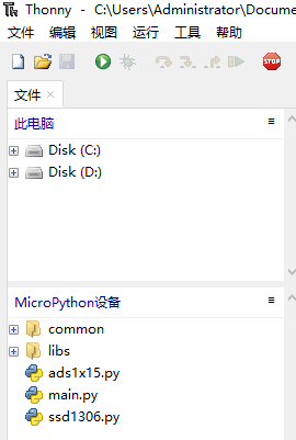
time.sleep(0.5) 复制代码 完成后文件目录如下图所示:
四、实验结果
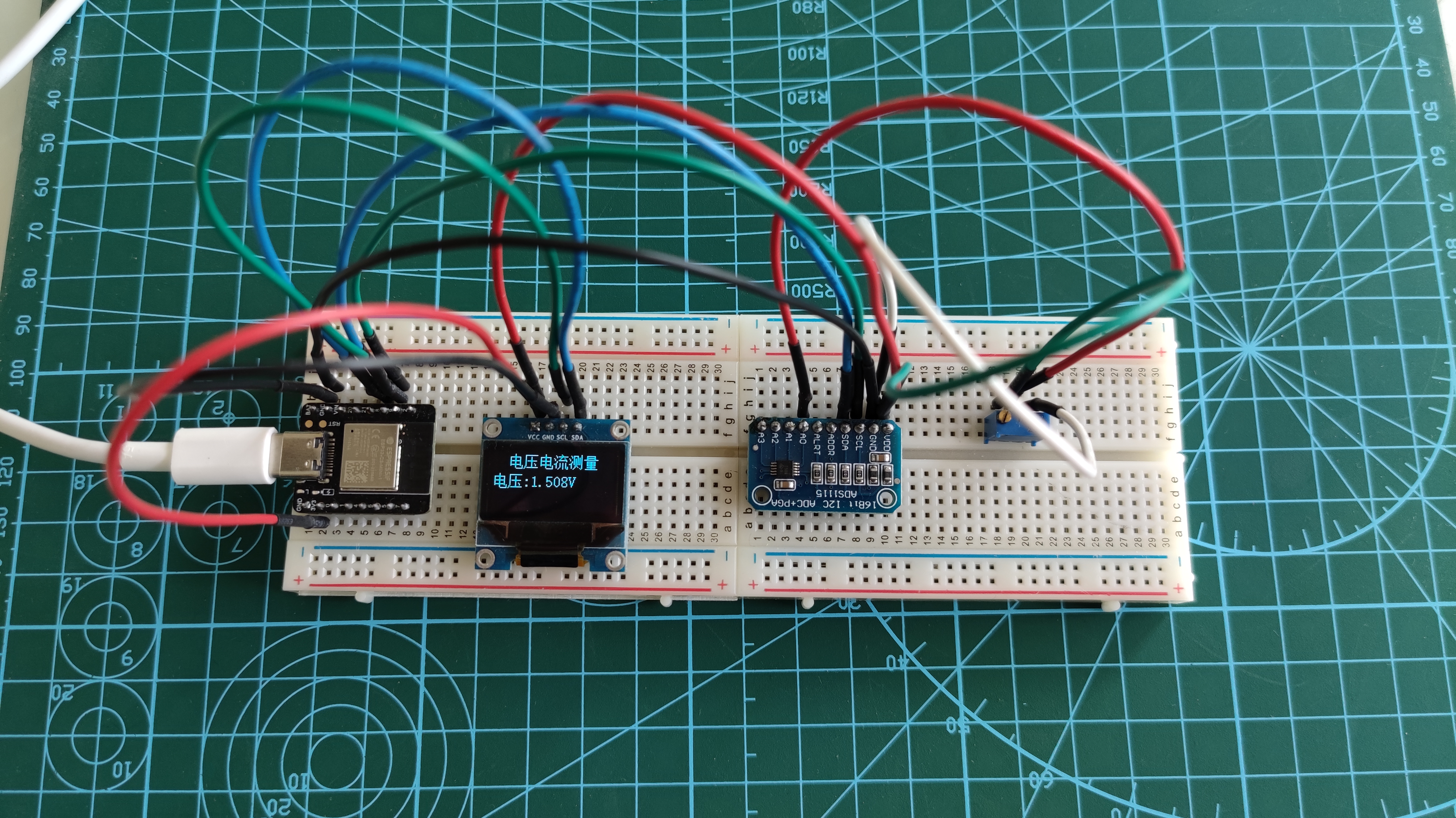
下图是连接成功,运行程序,进行测量电压的照片:
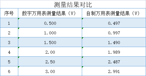
下表是利用自制电压表和数字万用表测量结果对比,由表中可以看出,自制数字电压表测量结果和数字万用表测量结果基本一致,实验取得基本成功。
近期学校事务较多,时间紧张,实验进行的比较简略和粗糙,我会在以后继续完善和扩充,请各位批评指正。实验中所用图片、库和部分代码,参考了网络资源,仅作为自己学习之用,如有侵权,请联系我修改删除。
 一、项目由来
 沪公网安备31011502402448