|
2644| 2
|
[项目] 【Arduino 动手做】ESP32 + BaseCam 蓝牙云台控制 |
|
BaseCam 无刷云台控制器 (BGC) 系列产品广泛用于电影摄影行业的相机云台控制和稳定系统,此处提供了 YouTube 介绍性视频: • BaseCam Electronics 简介 除了让 3 个 DM5005 万向节电机对 BaseCam Extended Long 控制器板上的板载 IMU 做出反应外,我还希望能够读取和处理来自 3 个独立单轴纵杆的信号,以通过 BaseCam 控制器板控制这些相同万向节电机的滚动、俯仰和偏航。为此,我使用 ESP32 微控制器从纵杆读取输入,并将这些值中继到 BaseCam 控制器,一种情况下是直接有线,另一种情况下是通过 2 个 ESP32 板使用低功耗蓝牙 (BLE) 无线传输。 BaseCam 系列万向节控制器具有接收不同信号类型的功能,包括 PWM 和模数 (ADC) 读数。但是,我希望通过 ESP32-S3 开发板来控制信号在 BaseCam 控制器读入之前的处理方式。该项目的布线和设置允许进行这种类型的控制,无论是直接有线还是使用 BLE 无线。我希望它对您的下一个 BaseCam 项目有用! 用品 1.3 x 单轴纵杆模块 2.2 x ESP32-S3 DevKitC 开发板 3.1 x Basecam BGC Extended Long 控制器 4.1 x 面包板 5.1 x 22AWG 实心线 6.1 x 各种多色热缩管 7.1 x 各种跳线 8.2 x Micro-USB 转 USB-A 电缆 9.1 x 1.25mm 预压接连接器套件(用于 BaseCam Extended Long 板的 CANbus 连接器) 10.1 x 烙铁 11.1 x 焊料卷 12.1 x 电池组 13.1 x 各种预压接 ZH 1.5mm 连接器(用于 CAN 驱动板) 14.1 x 4S 锂聚合物 (LiPo) 电池 15.1 x XT-60 电池连接器 16.1 个 2 针 JST-XH 连接器,用于将 LiPo 电池连接到 BaseCam 电池针脚 17.1 x 各种 M2 黄铜支座和螺钉套装(用于演示组装) 18.1 台 FDM 3D 打印机 19.1 x 1 千克卷轴 1.75 毫米厚的黑色 PLA+ 线材 20.1 x 各种夹式线连接器(可选,可用于原型设计) 21.1 x 扎带套装(可选,用于电线管理) 对于仅使用 1 个 ESP32-S3 开发板读取数据的情况,3 个单轴摇杆将 3 个摇杆中的每一个的 VCC 和 GND 分别连接到 ESP32 板上的 3V3 和 GND。摇杆模块充当弹簧加载的电位器,因此我们将使用具有模数转换 (ADC) 功能的 ESP32 引脚(GPIO4、GPIO5、GPIO6)。我们将使用 ESP32 上的硬件 Serial1 引脚(GPIO17、GPIO18)连接到 BaseCam 控制器板上的 UART1_RX、UART1_TX 引脚。请注意,ESP32 上的 RX 引脚连接到 BaseCam 板上的 TX 引脚,反之亦然。如果您想从 BaseCam 板为 ESP32 供电,请将两块板上的 5V 引脚连接在一起,然后将两块板上的 GND 引脚连接在一起。将 BaseCam 板连接到您的计算机以提供 5V 电源,并在 BaseCam Simple GUI 软件和控制器板之间进行通信。 引脚连接摘要: ESP32 GPIO6 - 摇杆 #1 SIG 引脚(白色) ESP32 GPIO7 - 摇杆 #2 SIG 引脚(绿色) ESP32 GPIO15 - 摇杆 #3 SIG 引脚(紫色) ESP32 RX (GPIO18) - BaseCam UART1_TX 引脚(蓝色) ESP32 TX (GPIO17) - BaseCam UART1_RX 引脚(绿色) ESP32 5V 引脚 - BaseCam 5V 引脚(红色) ESP32 3V3 引脚 - 连接到所有 3 个摇杆 VCC 引脚(黄色) ESP32 GND 引脚 - 连接到所有 3 个纵杆 GND 引脚,以及 BaseCam GND 引脚(黑色) 电池正极(红色)端子 - 并联连接到所有 3 个万向节电机驱动器的 VCC 引脚,以及 BaseCam 板上的 +BAT 引脚。 电池负极(黑色)端子 - 并联连接到所有 3 个万向节电机驱动器的 GND 引脚,以及 BaseCam 板上的电池 GND 引脚(正极 BAT+ 引脚下方)。 BaseCam CAN_H 针 - 与 CANH 针并联,全部在所有 3 个云台电机驱动器上(黄线) BaseCam CAN_L 针 - 与 CANL 针并联,全部在所有 3 个云台电机驱动器上(蓝线) 对于使用 2 个 ESP32 将摇杆信息中继到 BaseCam 控制器的情况下,第一个客户端/主 ESP32 读取 3 个摇杆,并将这些读数持续发送到第二个外设/从属 ESP32,后者又使用 BaseCam API 将它们中继到 BaseCam 控制器。在布线方面,这只是意味着从外设 ESP32 上移除 3 个摇杆连接,而是将它们连接到客户端 ESP32。所有其他接线与 Direct Wiring 情况相同。此外,主客户端 ESP32-S3 开发板可以由任何 5V 电源供电,例如电池组、笔记本电脑 USB 端口或通过 micro-USB 转 USB-A 电缆的壁挂式 5VDC 电源。 该项目成功演示了如何将命令从 ESP32-S3 开发板发送到 BaseCam 云台控制器板,以便通过 CANbus 连接控制云台电机。您也可以通过低功耗蓝牙将信号从一个 ESP32 发送到另一个 ESP32,为您的 BaseCam 控制器添加无线功能! 以下是进一步推进此项目的一些想法: 构建具有三个或更多轴的自定义完整万向节组件,并将此处提到的电子设备合并到该组件中。这可用于远程控制的摄像机监控、电影摄影、机器人遥测等。 添加基于 ESP32 的电容式触摸屏模块,带有屏幕按钮和文本字段,用于创建、更改、保存和修改发送到 BaseCam 控制板的设置和命令。 设计并 3D 打印一个外壳,以容纳客户端 ESP32 模块和用户界面设备(纵杆等),以创建便携式电池供电的万向节控制器。 使用 KiCAD 设计和使用基于 ESP32 的定制 PCB。 试验各种输入设备,如电位计旋钮、触觉开关和其他输入传感器和开关,以扩展用户与 BaseCam 板的交互方式。 使用一对带有 EMT 导管的耦合器创建一个可伸缩的 EMT 导管监控杆,并在杆顶部附近安装一个摄像头万向节,并沿杆安装控制电子设备。 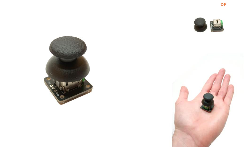 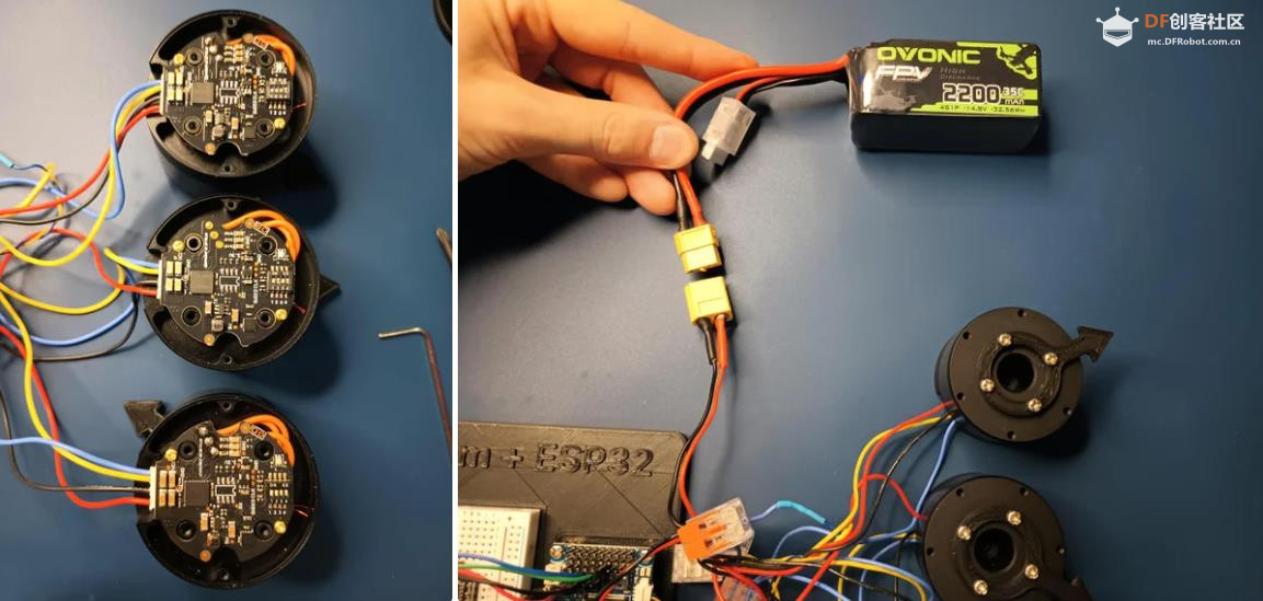 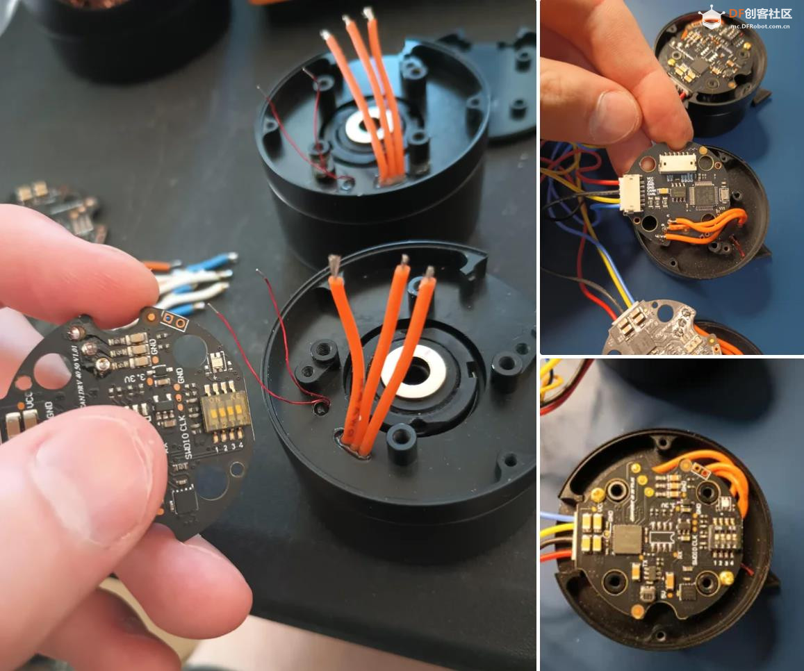 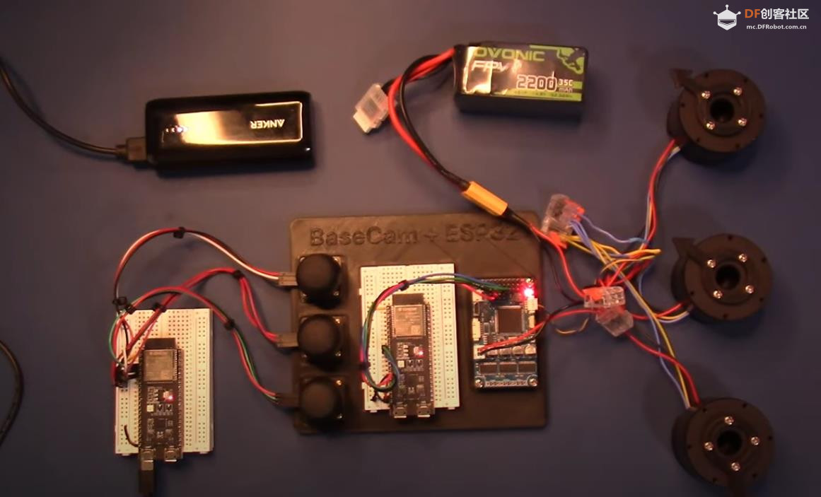 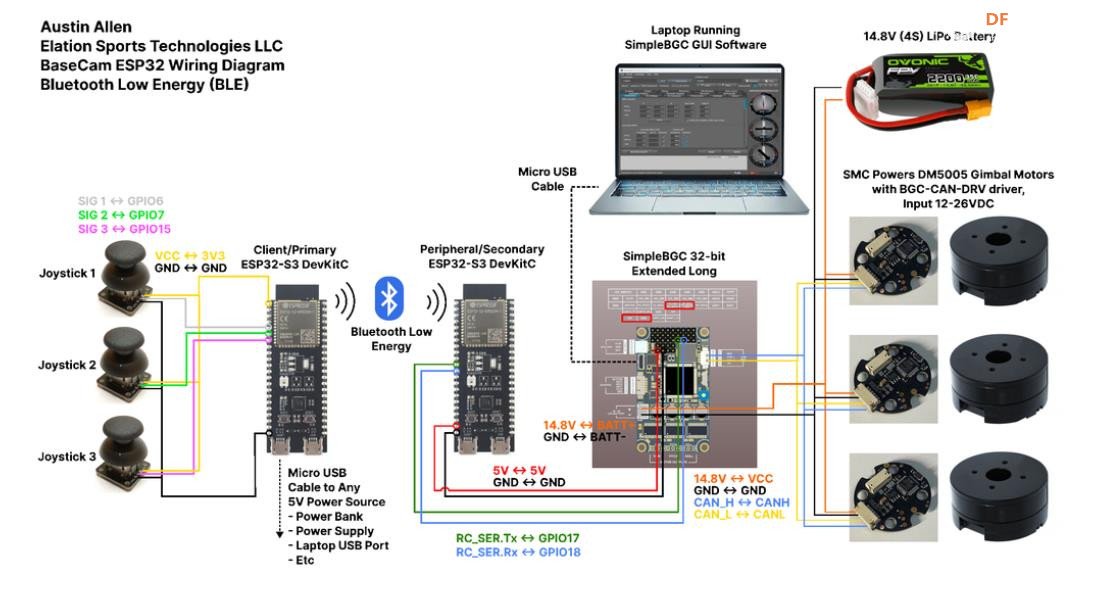 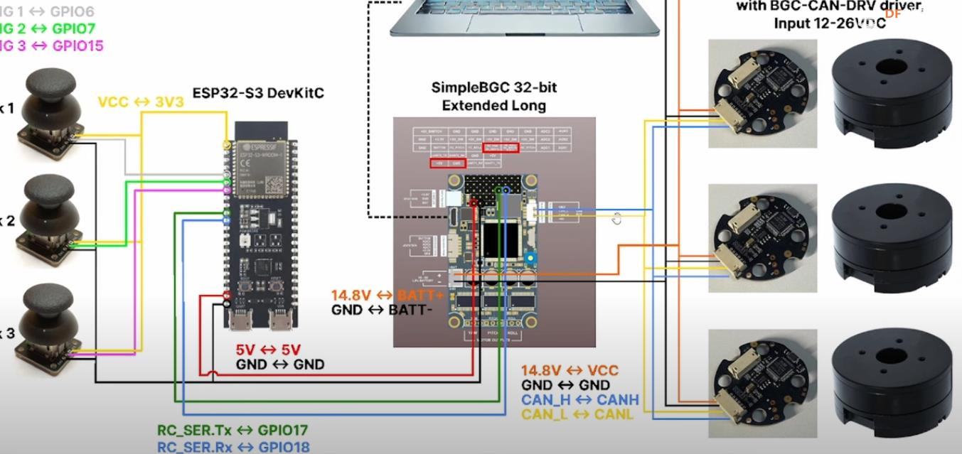 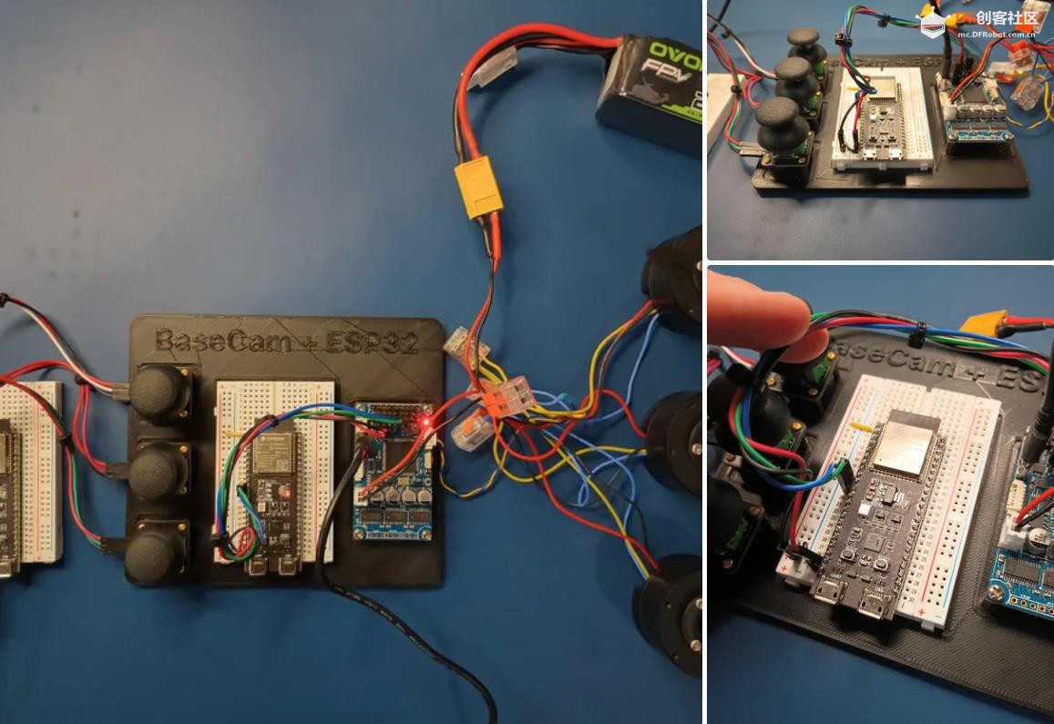 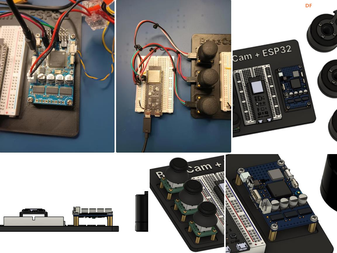 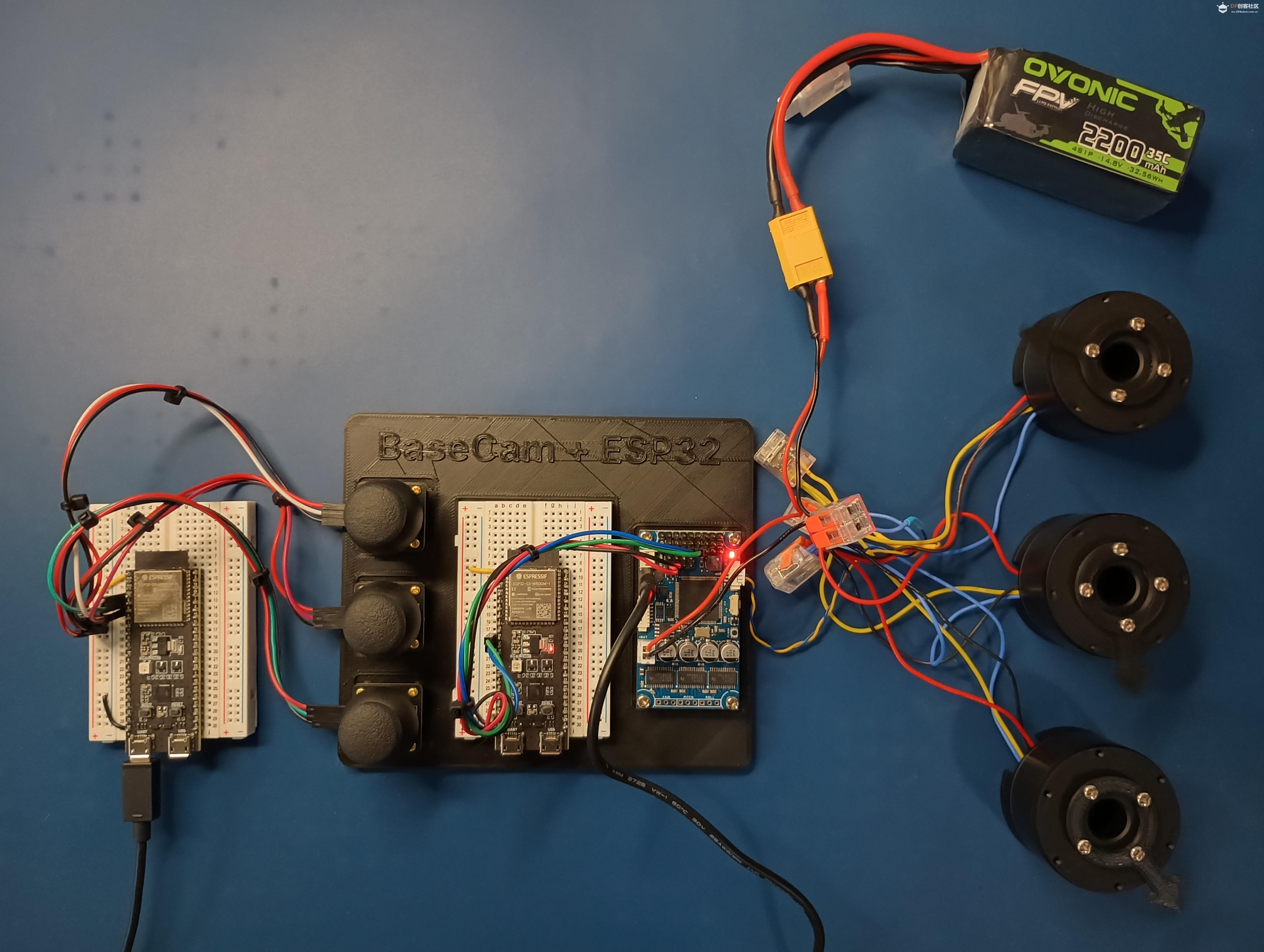 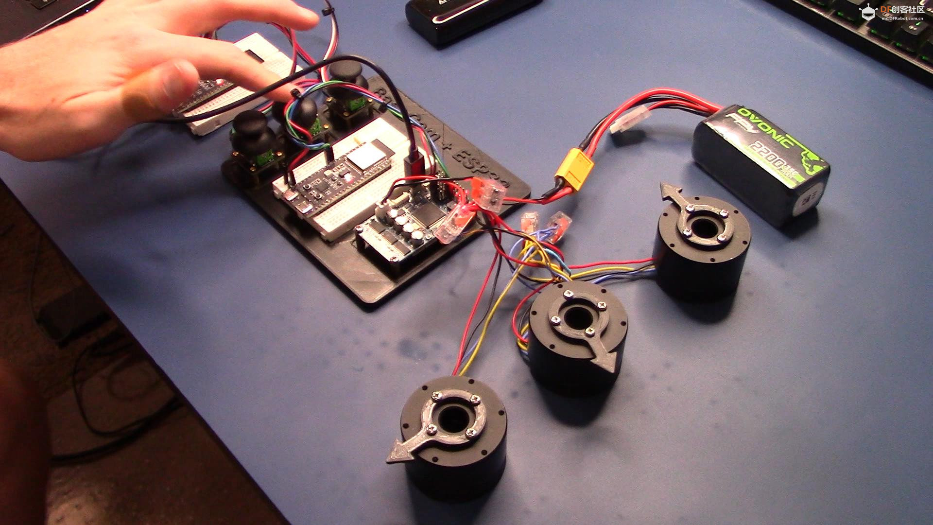 |
项目代码 |
|
【Arduino 动手做】ESP32 + BaseCam 蓝牙云台控制 项目链接:https://www.instructables.com/ES ... oth-Gimbal-Control/ 项目作者:洛杉矶 Penguingineer 项目视频:https://www.youtube.com/watch?v=7FAC-9hZs3E 项目代码:https://github.com/TheESTest/BaseCam-ESP32-Controller 3D打印文件: https://content.instructables.co ... F5FGMA9LZCPTYUF.stl https://content.instructables.co ... FS9VR2OLZCPTYTN.stl API 库:https://github.com/basecamelectronics/sbgc32-se-rial-ap CAN 接线和通信协议文档:https://content.instructables.co ... F9KOFQOLZCPTR48.pdf 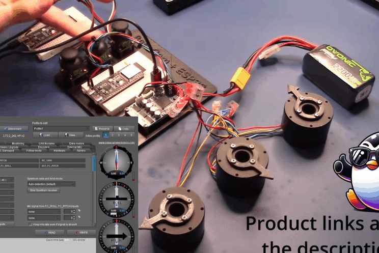 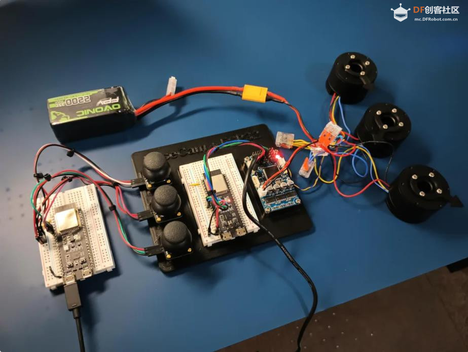 |


 沪公网安备31011502402448
© 2013-2026 Comsenz Inc. Powered by Discuz! X3.4 Licensed

 置顶卡
置顶卡 变色卡
变色卡 千斤顶
千斤顶
 萌萌哒新人
萌萌哒新人
 活跃会员
活跃会员
 宣传大使
宣传大使
 牛X认证
牛X认证
 创作达人
创作达人
 ARD DAY
 摸鱼团员
摸鱼团员
 志“童”道合
 编辑选择奖
编辑选择奖


