

【转】使用4017数字集成块扩展Arduino开关阵列
2013-12-052.2万

AI 快速预览详细
本文介绍了如何使用4017数字集成块扩展Arduino开关阵列。通过分时复用技术,可以显著减少引脚占用,适用于需要大量开关控制的项目。4017数字集成块的特点是十个开关仅占用三个数据引脚,每增加十个开关只需增加一个引脚。文章详细讲解了电路工作原理,并提供了Arduino程序示例。
|
作者注:此方法并非扩展输入脚最佳方法,如果需要大量扩展输入脚的话(几十甚至上百路),可以使用74HC165或者CD4021做shiftin。而不是本文的4017。 http://playground.arduino.cc/Code/ShiftRegSN74HC165N http://www.arduino.cc/en/Tutorial/ShiftIn The SN74HC165N is an 8-bit parallel-load or serial-in shift registers with complementary serial outputs available from the last stage. When the parallel load (PL) input is LOW, parallel data from the D0 to D7 inputs are loaded into the register asynchronously. When PL is HIGH, data enters the register serially at the Ds input and shifts one place to the right (Q0 → Q1 → Q2, etc.) with each positive-going clock transition. This feature allows parallel-to-serial converter expansion by tying the Q7 output to the DS input of the succeeding stage. Breadboard SchematicThe following image shows 10 pushbuttons wired to two SN74HC165N input shift registers. Note that the 6 unused input pins are grounded. 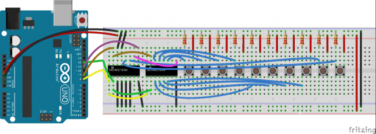 CodeThe following code demonstrates reading in 16 digital states from a pair of daisy-chained SN74HC165N shift registers while using only 4 digital pins on the Arduino. [mw_shl_code=applescript,true]/* * SN74HC165N_shift_reg * * Program to shift in the bit values from a SN74HC165N 8-bit * parallel-in/serial-out shift register. * * This sketch demonstrates reading in 16 digital states from a * pair of daisy-chained SN74HC165N shift registers while using * only 4 digital pins on the Arduino. * * You can daisy-chain these chips by connecting the serial-out * (Q7 pin) on one shift register to the serial-in (Ds pin) of * the other. * * Of course you can daisy chain as many as you like while still * using only 4 Arduino pins (though you would have to process * them 4 at a time into separate unsigned long variables). * */ /* How many shift register chips are daisy-chained. */ #define NUMBER_OF_SHIFT_CHIPS 2 /* Width of data (how many ext lines). */ #define DATA_WIDTH NUMBER_OF_SHIFT_CHIPS * 8 /* Width of pulse to trigger the shift register to read and latch. */ #define PULSE_WIDTH_USEC 5 /* Optional delay between shift register reads. */ #define POLL_DELAY_MSEC 1 /* You will need to change the "int" to "long" If the * NUMBER_OF_SHIFT_CHIPS is higher than 2. */ #define BYTES_VAL_T unsigned int int ploadPin = 8; // Connects to Parallel load pin the 165 int clockEnablePin = 9; // Connects to Clock Enable pin the 165 int dataPin = 11; // Connects to the Q7 pin the 165 int clockPin = 12; // Connects to the Clock pin the 165 BYTES_VAL_T pinValues; BYTES_VAL_T oldPinValues; /* This function is essentially a "shift-in" routine reading the * serial Data from the shift register chips and representing * the state of those pins in an unsigned integer (or long). */ BYTES_VAL_T read_shift_regs() { long bitVal; BYTES_VAL_T bytesVal = 0; /* Trigger a parallel Load to latch the state of the data lines, */ digitalWrite(clockEnablePin, HIGH); digitalWrite(ploadPin, LOW); delayMicroseconds(PULSE_WIDTH_USEC); digitalWrite(ploadPin, HIGH); digitalWrite(clockEnablePin, LOW); /* Loop to read each bit value from the serial out line * of the SN74HC165N. */ for(int i = 0; i < DATA_WIDTH; i++) { bitVal = digitalRead(dataPin); /* Set the corresponding bit in bytesVal. */ bytesVal |= (bitVal << ((DATA_WIDTH-1) - i)); /* Pulse the Clock (rising edge shifts the next bit). */ digitalWrite(clockPin, HIGH); delayMicroseconds(PULSE_WIDTH_USEC); digitalWrite(clockPin, LOW); } return(bytesVal); } /* Dump the list of zones along with their current status. */ void display_pin_values() { Serial.print("Pin States:"); for(int i = 0; i < DATA_WIDTH; i++) { Serial.print(" Pin-"); Serial.print(i); Serial.print(": "); if((pinValues >> i) & 1) Serial.print("HIGH"); else Serial.print("LOW"); Serial.print(""); } Serial.print(""); } void setup() { Serial.begin(9600); /* Initialize our digital pins... */ pinMode(ploadPin, OUTPUT); pinMode(clockEnablePin, OUTPUT); pinMode(clockPin, OUTPUT); pinMode(dataPin, INPUT); digitalWrite(clockPin, LOW); digitalWrite(ploadPin, HIGH); /* Read in and display the pin states at startup. */ pinValues = read_shift_regs(); display_pin_values(); oldPinValues = pinValues; } void loop() { /* Read the state of all zones. */ pinValues = read_shift_regs(); /* If there was a chage in state, display which ones changed. */ if(pinValues != oldPinValues) { Serial.print("*Pin value change detected*"); display_pin_values(); oldPinValues = pinValues; } delay(POLL_DELAY_MSEC); }[/mw_shl_code] 使用Arduino做制作,需要有一组开关控制Arduino状态。但是Arduino引脚不多,传统接法开关多了要占用很多引脚。减少引脚的方法有很多,可以选矩阵方式,编码器方式,还有本文要介绍的分时复用开关法等。 特点:十个开关占用三个数据引脚,之后每增加十个开关就增加一个引脚。 4017是一块十进制计数器,每输入一个CLK脉冲,Q0~Q9轮流产生高电平。每时刻有且只有一个引脚高电平。 二极管防止多个开关闭合时,有的输出端输出高电平,有的输出低电平,互相接上的话,会低电平引脚会干扰高电平脚的工作。 开关用10路拨动式小型开关,或者自己选择其他开关形式。 电路工作原理: 先在RST(4017的复位脚MR)发出一个脉冲,使4017复位。 此时有且只有Q0输出高电平(Q0对应开关S1,Q9对应开关S10),读取一次输出信号DATA。如果第一个开关S1闭合了,应该DATA得到高电平;如果S1断开了,就DATA得到低电平。此时记DATA结果对应第一个开关S1的状态。 给CLK输出一个脉冲,让4017移位,有且只有Q1输出高电平(Q0,Q2~Q9均为低电平)。读取DATA。得到S2状态。 不断给CLK脉冲。总共给10次脉冲,让4017由Q0移动到Q9,完成一次开关遍历,每次移动获取一次DATA状态。存为S1~S10状态。 电路原理图如图: 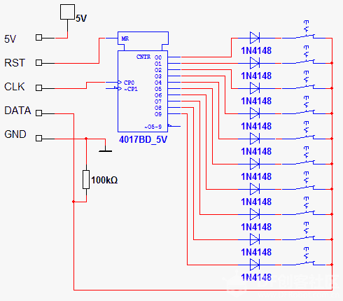 洞洞板图(由于引脚多,不建议面包板制作。) 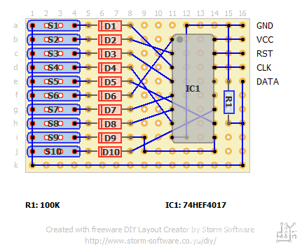 关于在一块Arduino上使用多块模块:每增加一块模块,可以增加十路开关(当然你也可以使用两块4017做成行列矩阵控制100个开关。不过那个就属于另外话题了)。增加的方式是将两块模块的RST,CLK,VCC,GND接在一起,接到单片机的相应引脚,然后两个模块的DATA脚分别接单片机两个IO口。 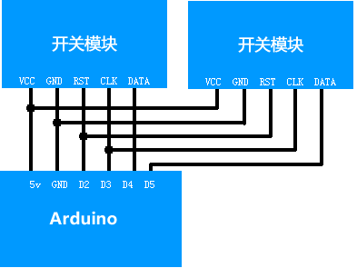 Arduino程序例子: [mw_shl_code=applescript,true]const int rst = 2; //板子的RST脚接Arduino的D4口(自定义) const int clk = 3; //板子的CLK脚接Arduino的D3口(自定义) const int data1 = 4; //板子的DATA脚接Arduino的D2口(自定义) //const int data2 = 5; //如果有第二块板子的话,两块板子共用RST和CLK引脚。DATA接Arduino的D5口,第三块板子可以类推接D6口(自定义) void setup() { Serial.begin(9600); pinMode(rst, OUTPUT); pinMode(clk, OUTPUT); pinMode(data1, INPUT); //pinMode(data2,INPUT); //如果有第二块板子的话要定义IO } void loop() { int KeyStatus[10] = {0}; //按照总开关数定义。可能要改为20,30等 digitalWrite(rst, HIGH); delayMicroseconds(10); //所有delayMicroseconds(10);均是给4017一个反应时间。 digitalWrite(rst, LOW); delayMicroseconds(10); for(int i = 0; i < 10; i++) { KeyStatus = digitalRead(data1); //KeyStatus[i+10] = digitalRead(data2); //读取第二个板子的状态,地址放在i+10 digitalWrite(clk, HIGH); delayMicroseconds(10); digitalWrite(clk, LOW); delayMicroseconds(10); } for(int i = 0; i < 10; i++) //循环打印KeyStatus数组,i<10可能要改为i<20,30等 { Serial.print(KeyStatus); Serial.print(" "); } Serial.println(); delay(100); }[/mw_shl_code] 洞洞板实物图: 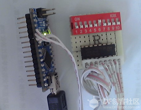 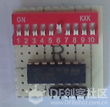 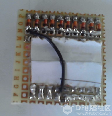 |