

【Arduino 动手做】在 VFD 显示屏上 DIY 音频频谱分析仪
2025-06-211522
AI 快速预览详细
本文介绍了如何使用Arduino纳米微控制器和VFM202MDA1-1型VFD显示器制作音频频谱分析仪。硬件清单包括Arduino纳米微控制器、VFD显示器、立体声电位器和两个电容器。使用fix_fft库进行音频信号处理,最终效果非常明亮且具有复古外观。该设备内置于一个由PVC材料制成的盒子中,显示屏正面放置了一层薄而透明的滤光箔。
|
频谱分析仪是一种测量工具,可显示传入音频信号的实时频率分析。 它通常是均衡器和音频信号处理设备的组成部分。纵轴表示以分贝为单位测量的特定频率的振幅。 这次我将向您展示如何在 20x2 VFD 显示屏上制作这样的设备。在我之前的某个视频中,您可以看到如何在这样的显示屏上制作音量表。这些显示屏的优点在于它们发出非常明亮的光线,对比度高,并且具有漂亮的复古外观。在我之前提到的视频 ( https://www.youtube.com/watch?v=gotUokTuP9U ) 中,您可以看到如何修改这样的显示屏,然后您可以使用适用于 16x2 字符 LCD 和 HD44780 驱动芯片的库。具体来说,在本例中,我们使用“LiquidCrystal”库来控制这个 VFD 显示屏。 所展示的设备构建非常简单,由几个组件组成: - Arduino 纳米微控制器 - VFM202MDA1-1型VFD显示器略有修改 - 立体声电位器控制输入信号的强度 - 和两个电容器 用于分析和处理音频信号的库是“fix_fft”库。代码基础取自Ray Burnette,并进行了一些细微调整。新代码适用于20x2字符,提高了噪声敏感度阈值,并进行了一些细微的视觉校正。该设备内置于一个合适的盒子中,盒子由厚度为3毫米和5毫米的PVC材料制成,并贴有自粘墙纸。显示屏正面放置了一层薄而透明的滤光箔。 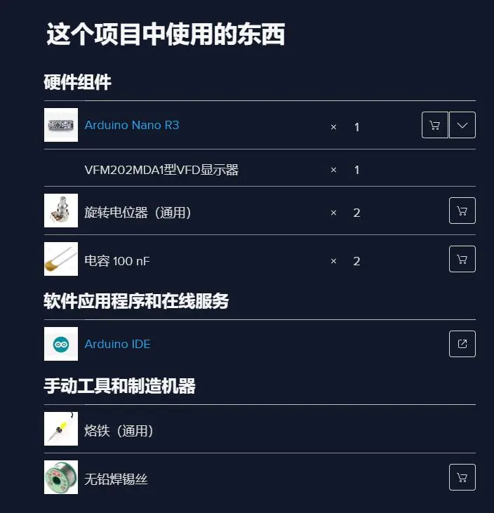 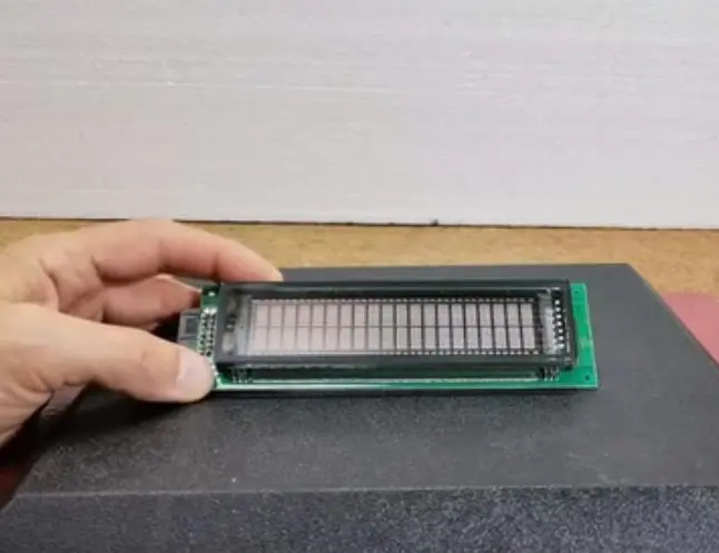 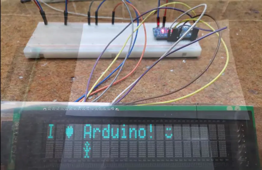 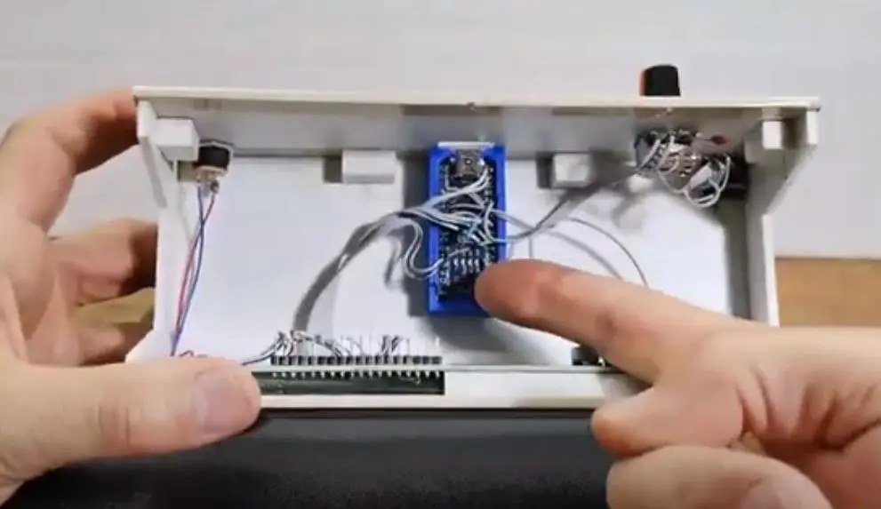 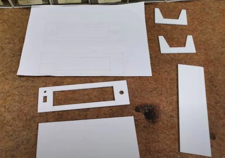 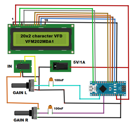 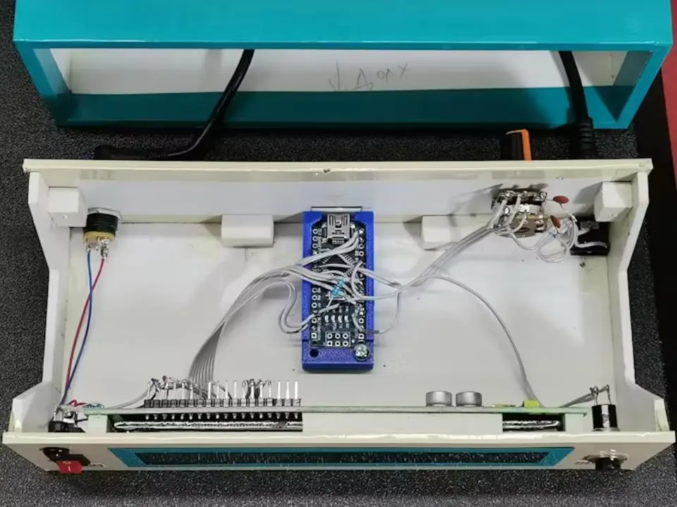 |

项目链接:https://www.hackster.io/mircemk/diy-arduino-audio-spectrum-analyzer-on-vfd-display-655c10
项目作者:北马其顿 米尔塞姆克(Mirko Pavleski)
项目参考:https://www.youtube.com/watch?v=gotUokTuP9U
项目视频 :https://www.youtube.com/watch?v=MmLOjRUFaSg
项目代码:https://www.hackster.io/code_files/594048/download
[code]/* FFT_TEST4
Ray Burnette 20130810 function clean-up & 1284 port (328 verified)
Uses 2x16 Parallel LCD in 4-bit mode, see LiquidCrystal lib call for details
http://forum.arduino.cc/index.php?PHPSESSID=4karr49jlndufvtlqs9pdd4g96&topic=38153.15
Modified by varind in 2013: this code is public domain, enjoy!
http://www.variableindustries.com/audio-spectrum-analyzer/
328P = Binary sketch size: 5,708 bytes (of a 32,256 byte maximum)
1284P= Binary sketch size: 5,792 bytes (of a 130,048 byte maximum) Free RAM = 15456
Binary sketch size: 8,088 bytes (of a 130,048 byte maximum) (Debug)
*/
#include
#include
#include
#define DEBUG 0
#define L_IN 3 // Audio input A0 Arduino
#define R_IN 2 // Audio input A1 Arduino
const int Yres = 8;
const int gain = 3;
float peaks[64];
char im[64], data[64];
char Rim[64], Rdata[64];
char data_avgs[64];
int debugLoop;
int i;
int load;
LiquidCrystal lcd(12, 11, 5, 4, 3, 2);// RS,E,D4,D5,D6,D7
// Custom CHARACTERS
byte v1[8] = {
B00000, B00000, B00000, B00000, B00000, B00000, B00000, B11111
};
byte v2[8] = {
B00000, B00000, B00000, B00000, B00000, B00000, B11111, B11111
};
byte v3[8] = {
B00000, B00000, B00000, B00000, B00000, B11111, B11111, B11111
};
byte v4[8] = {
B00000, B00000, B00000, B00000, B11111, B11111, B11111, B11111
};
byte v5[8] = {
B00000, B00000, B00000, B11111, B11111, B11111, B11111, B11111
};
byte v6[8] = {
B00000, B00000, B11111, B11111, B11111, B11111, B11111, B11111
};
byte v7[8] = {
B00000, B11111, B11111, B11111, B11111, B11111, B11111, B11111
};
byte v8[8] = {
B11111, B11111, B11111, B11111, B11111, B11111, B11111, B11111
};
void setup() {
if (DEBUG) {
Serial.begin(9600); // hardware serial
Serial.print("Debug ON");
Serial.println("");
}
lcd.begin(16,2);
lcd.clear();
lcd.createChar(1, v1);
lcd.createChar(2, v2);
lcd.createChar(3, v3);
lcd.createChar(4, v4);
lcd.createChar(5, v5);
lcd.createChar(6, v6);
lcd.createChar(7, v7);
lcd.createChar(8, v8);
for (i=0;i<100;i++)
{
for (load = 0; load < i / 5; load++)
{
lcd.setCursor(load, 1);
lcd.write(5);
}
if (load < 1)
{
lcd.setCursor(0, 1);
lcd.write(5);
}
lcd.setCursor(load + 1, 1);
lcd.write((i - i / 5 * 5) + 1);
for (load = load + 2; load < 20; load++)
{
lcd.setCursor(load, 1);
lcd.write(9);
}
lcd.setCursor(0, 0);
lcd.print("LOADING.............");
delay(10);
}
lcd.clear();
delay(10);
}
void loop() {
for (int i = 0; i < 64; i++) { // 64 bins = 32 bins of usable spectrum data
data[i] = ((analogRead(L_IN) / 8 ) - 256); // chose how to interpret the data from analog in
im[i] = 0; // imaginary component
Rdata[i] = ((analogRead(R_IN) / 8 ) - 256); // chose how to interpret the data from analog in
Rim[i] = 0; // imaginary component
}
fix_fft(data, im, 6, 0); // Send Left channel normalized analog values through fft
fix_fft(Rdata, Rim, 6, 0); // Send Right channel normalized analog values through fft
// At this stage, we have two arrays of [0-31] frequency bins deep [32-63] duplicate
// calculate the absolute values of bins in the array - only want positive values
for (int i = 0; i < 40; i++) {
data[i] = sqrt(data[i] * data[i] + im[i] * im[i]);
Rdata[i] = sqrt(Rdata[i] * Rdata[i] + Rim[i] * Rim[i]);
// COPY the Right low-band (0-15) into the Left high-band (16-31) for display ease
if (i < 20) {
data_avgs[i] = data[i];
}
else {
data_avgs[i] = Rdata[i - 20];
}
// Remap values to physical display constraints... that is, 8 display custom character indexes + "_"
data_avgs[i] = constrain(data_avgs[i], 0, 9 - gain); //data samples * range (0-9) = 9
data_avgs[i] = map(data_avgs[i], 0, 9 - gain, 0, Yres); // remap averaged values
}
Two16_LCD();
decay(1);
}
void Two16_LCD() {
lcd.setCursor(0, 0);
lcd.print("L"); // Channel ID replaces bin #0 due to hum & noise
lcd.setCursor(0, 1);
lcd.print("R"); // ditto
for (int x = 1; x < 20; x++) { // init 0 to show lowest band overloaded with hum
int y = x + 20; // second display line
if (data_avgs[x] > peaks[x]) peaks[x] = data_avgs[x];
if (data_avgs[y] > peaks[y]) peaks[y] = data_avgs[y];
lcd.setCursor(x, 0); // draw first (top) row Left
if (peaks[x] == 0) {
lcd.print("_"); // less LCD artifacts than " "
}
else {
lcd.write(peaks[x]);
}
lcd.setCursor(x, 1); // draw second (bottom) row Right
if (peaks[y] == 0) {
lcd.print("_");
}
else {
lcd.write(peaks[y]);
}
}
debugLoop++;
if (DEBUG && (debugLoop > 99)) {
Serial.print( "Free RAM = " );
Serial.println( freeRam(), DEC);
Serial.println( millis(), DEC);
debugLoop = 0;
}
}
int freeRam () {
extern int __heap_start, *__brkval;
int v;
return (int) &v - (__brkval == 0 ? (int) &__heap_start : (int) __brkval);
}
void decay(int decayrate) {
int DecayTest = 1;
// reduce the values of the last peaks by 1
if (DecayTest == decayrate) {
for (int x = 0; x < 40; x++) {
peaks[x] = peaks[x] - 1; // subtract 1 from each column peaks
DecayTest = 0;
}
}
DecayTest++;
}[/code]