

【Arduino 动手做】带 4x64 LED 矩阵的 Arduino Nano Clock (新...
2025-06-271520
AI 快速预览详细
这个项目是使用 Arduino Nano 和 4x64 LED 矩阵显示器制作的时钟。它支持日期、温度显示和亮度控制。通过 DS3231 实时时钟库和 MD_MAX722XX 库实现时间显示。用户可以在 Arduino 串行监视器中设置 RTC 时间。新代码使用 13558 字节(44%)和 372 字节(18%)作为变量,更短一些。
|
代码体积小,硬件简单。改进版本现已推出。 概述 在几米远的房间里读取时钟显示需要这样的 LED 矩阵显示器。 以优惠的价格购买了 4 单元显示器后,我在 Hackster 上查看了可用的项目:有几个用于 Arduino Nano 的项目。如果您想同时查看小时、分钟和秒:只有少数项目有效,因为您需要比每个数字 5x7 像素的广泛可用的数字更小的数字。一种选择是使用 MD_Parola 库,但代码大小对于简单的 clock来说太大了。另一个测试选项是 Max72xxPanel 库,但这太旧了,需要调用其他库。最后,该项目基于基本接口库 MD_MAX722XX,包含在所有其他接口库中。 此站点的评论使我回顾了硬件方面和代码。 - 有许多名为 DS3231 的库。我使用这个:http://www.rinkydinkelectronics.com/library.php?id=73 DS3231 I2C 实时时钟的 Arduino/chipKit 库版权所有 (C)2015 Rinky-Dink Electronics, Henning Karlsen.版权所有 - 首先:LED 矩阵显示。市面上有几种型号,所以很有可能上传这段代码后显示屏会显示奇怪的东西。解决方案:从 “MD_MAX72xx_lib.h” 库 “MD_MAX72xx_HW_Mapper.ino” 上传此示例并找到您的硬件型号。在我的代码中,模型被定义:#define HARDWARE_TYPE MD_MAX72XX::ICSTATION_HW,但在您设置正确的模型之前,这可能不起作用! - 漂亮的小秒针最近没有出现吗?现在 (v2),这些秒的字体包含在代码中,因此无需更改任何其他库。 - 由于 Arduino 更新,出现较长的编译警告列表。现在,月份位于二维 char 数组中,不再使用指针。任何其他警告都来自 DS3231.h 库,但可以忽略。 - 闪烁的点现在只有 2 个点!准确的秒数使用我的 3x5 字体显示在 “hh:mm” 之后。此外,列点 “:” 几乎每秒闪烁两次,只是为了表明它是活的! - Answering a request :时间每分钟显示 53 秒,最后 7 秒显示日期和温度。 - 如果您在 loop() 中取消注释两行,也可以显示星期几。在这种情况下,您可能希望将 53 秒的间隔减少到 51 秒。 - 如果您更喜欢 12 小时格式,请参阅我的一个较早的答案。 - 可以在 Arduino 串行监视器中设置 RTC 时间,方法是在输入区域 DD/MM/YYYY hh:mm:ss(不要忘记两者之间的空格)并按 Enter/Send。只要连接了 USB 电缆并且 Serial Monitor 正常工作(正确的 COM 和波特率),就可以执行此作。 新代码使用 13558 字节 (44%) 和 372 字节 (18%) 作为变量,因此它更短一些! 日期显示为 “dd Mon” 和室温(以 deg 为单位)。摄氏度(使用 RTC 内部传感器估算)显示在单独的页面上。亮度由光敏电阻控制。但是,即使没有光传感器,该代码也可以正常工作。  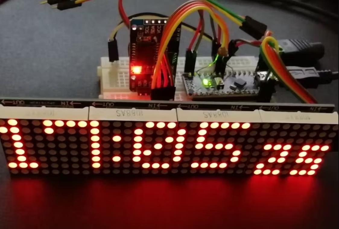 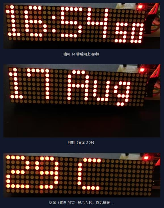 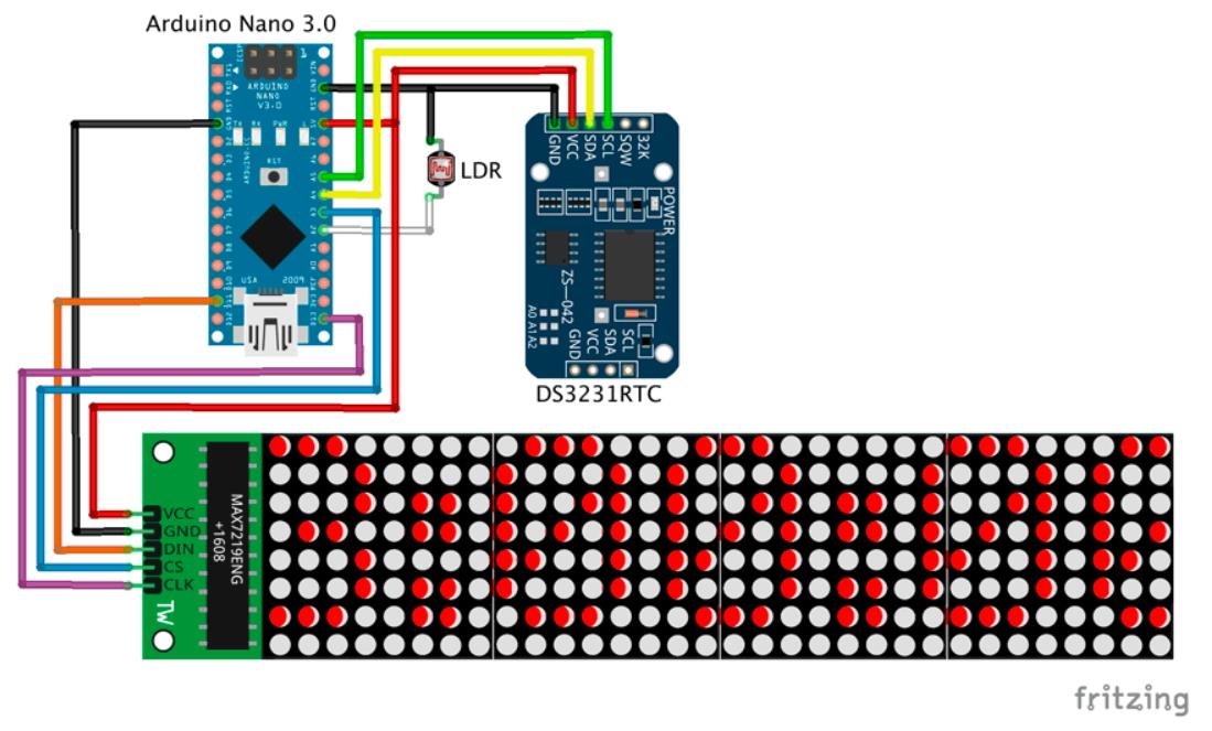 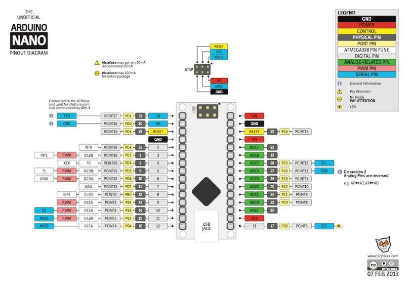 |


项目链接:https://www.hackster.io/M-V-P/ar ... -new-version-409730
项目作者:MVP
项目代码:
https://github.com/leonardosposina/arduino-led-dot-matrix-clock
https://www.hackster.io/code_files/275179/download
https://www.hackster.io/code_files/522090/download
[code]/* Arduino Nano DS3231 clock with LED Matrix 4x(8x8) SPI
* Version 2 - updated 15/05/2-21
* Arduino Nano 5V logic - 32kB prog. space
* Tools:Board: Arduino Nano; Processor: ATmega328P (Old Bootloader)!!
* LED Matrix 4x(8x8) SPI with connector on the right side (last module)
* https://www.banggood.com/MAX7219-Dot-Matrix-Module-4-in-1-Display-For-Arduino-p-1072083.html?rmmds=myorder&cur_warehouse=CN
*
* CONNECTIONS:
* >> LCD 4x64 -> Arduino Nano: (using Hardware SPI):
* 5V -> 5V pin
* GND -> GND pin
* CLK_PIN -> 13 // or SCK
* DATA_PIN -> 11 // or MOSI
* CS_PIN -> 10 // or SS
*
* >> DS3231 RTC -> Arduino Nano:
* SDA (DAT) -> A4
* SCL (CLK) -> A5
* Inspired by : 1) Arduino Clock by AnthoTRONICS Last edit: March 22,2019
* but without MD_parola because of its large footprint! New getdate function.
* 2) Simplest UNO Digital Clock Ever by plouc68000:
* https://create.arduino.cc/projecthub/plouc68000/simplest-uno-digital-clock-ever-4613aa?ref=user&ref_id=680368&offset=1
* 3) LEDDotMatrixClock.ino by Leonardo Sposina, but here without "Max72xxPanel.h"
* https://github.com/leonardosposina/arduino-led-dot-matrix-clock/blob/master/LEDDotMatrixClock/LEDDotMatrixClock.ino
* Not using Max72xxPanel.h, but small size digits are stll used. Small footprint code here.
*
* project: 113558 bytes (44%); variables 372 bytes (17%)
* Author: MVP https://www.hackster.io/M-V-P
*/
#include
#include "DS3231.h"
#include "MD_MAX72xx_lib.h"
//#include "Font_Data.h"
DS3231 rtc(SDA, SCL); // Real time clock
const byte LDR_PIN = A2; // LDR Sensor pin
#define MAX_DEVICES 4
// Define pins
#define CLK_PIN 13 // or SCK
#define DATA_PIN 11 // or MOSI
#define CS_PIN 10 // or SS
// Define below your LED matrix hardware model:
//#define HARDWARE_TYPE MD_MAX72XX::ICSTATION_HW
#define HARDWARE_TYPE MD_MAX72XX::FC16_HW
#define USE_NEW_FONT 1
#define BUF_SIZE 20 // text buffer size
#define CHAR_SPACING 1 // pixels between characters
char buf[BUF_SIZE], secs[4];
uint8_t hh, mm, ss, dots;
// Definition of the small fonts:
uint8_t Font3x5 [ 10 ][ 3 ]={
{ 248, 136, 248}, // 48 0
{144, 248, 128}, // 49 1
{200, 168, 184}, // 50 2
{136, 168, 248}, // 51 3
{112, 72, 224}, // 52 4
{184, 168, 232}, // 53 5
{248, 168, 232}, // 54 6
{8, 232, 24}, // 55 7
{248, 168, 248}, // 56 8
{184, 168, 248}}; // 57 9
char months[12][4]= {"Jan","Feb","Mar","Apr","May","Jun","Jul","Aug","Sep","Oct","Nov","Dec"};
char* wday;
// SPI hardware interface
// Max72xxPanel matrix = Max72xxPanel(CS_PIN, H_DISPLAYS, V_DISPLAYS);
MD_MAX72XX matrix = MD_MAX72XX(HARDWARE_TYPE, CS_PIN, MAX_DEVICES);
const byte WAIT = 100;
const byte SPACER = 1;
byte FONT_WIDTH;
bool timeset=false;
void adjustClock(String data) {
byte _day = data.substring(0,2).toInt();
byte _month = data.substring(3,5).toInt();
int _year = data.substring(6,10).toInt();
byte _hour = data.substring(11,13).toInt();
byte _min = data.substring(14,16).toInt();
byte _sec = data.substring(17,19).toInt();
rtc.setTime(_hour, _min, _sec);
rtc.setDate(_day, _month, _year);
Serial.println(F(">> Datetime successfully set!"));
timeset=true;
}
byte ledintensitySelect(int light) {
byte _value = 0;
if (light >= 0 && light <= 127) {
_value = 12;
} else if (light >= 128 && light <= 319) {
_value = 3;
} else if (light >= 320 && light <= 512) {
_value = 0;
}
return _value;
};
void printText(uint8_t modStart, uint8_t modEnd, char *pMsg)
// Print the text string to the LED matrix modules specified.
// Message area is padded with blank columns after printing.
{
uint8_t state = 0;
uint8_t curLen;
uint16_t showLen;
uint8_t cBuf[FONT_WIDTH];
int16_t col = ((modEnd + 1) * COL_SIZE) - 1;
matrix.control(modStart, modEnd, MD_MAX72XX::UPDATE, MD_MAX72XX::OFF);
do // finite state machine to print the characters in the space available
{
switch(state)
{
case 0: // Load the next character from the font table
// if we reached end of message, reset the message pointer
if (*pMsg == '\0')
{
showLen = col - (modEnd * COL_SIZE); // padding characters
state = 2;
break;
}
// retrieve the next character form the font file
showLen = matrix.getChar(*pMsg++, sizeof(cBuf)/sizeof(cBuf[0]), cBuf);
curLen = 0;
state++;
// !! deliberately fall through to next state to start displaying
case 1: // display the next part of the character
matrix.setColumn(col--, cBuf[curLen++]);
// done with font character, now display the space between chars
if (curLen == showLen)
{
showLen = CHAR_SPACING;
state = 2;
}
break;
case 2: // initialize state for displaying empty columns
curLen = 0;
state++;
// fall through
case 3: // display inter-character spacing or end of message padding (blank columns)
matrix.setColumn(col--, 0);
curLen++;
if (curLen == showLen)
state = 0;
break;
default:
col = -1; // this definitely ends the do loop
}
} while (col >= (modStart * COL_SIZE));
matrix.control(modStart, modEnd, MD_MAX72XX::UPDATE, MD_MAX72XX::ON);
}
void setup() {
pinMode(LDR_PIN, INPUT_PULLUP);
Serial.begin(9600);
Serial.println(F(">> Arduino 32x8 LED Dot Matrix Clock!"));
Serial.println(F(">> Use
rtc.begin();
matrix.begin();
matrix.clear();
FONT_WIDTH= 5 + SPACER; // The font width is 5 pixels
matrix.control(MD_MAX72XX::INTENSITY, 2);; // Use a value between 0 and 15 for brightness
rtc.setDOW(); // Required for a new RTC
}
void getDate()
// Date Setup: Code for reading clock date
{
String dts = rtc.getDateStr(); // Get dd/mm/yyyy string
String dds=dts.substring(0,2); // Extract date
String mms=dts.substring(3,5); // Extract month
int mm=mms.toInt(); // Convert to month number
dds.concat(" ");
dds.concat(String(months[mm-1])); // Rebuild date string as "dd Mmm"
dds.toCharArray(buf,sizeof(buf)); // return buffer
wday = rtc.getDOWStr(2);
}
void getHour()
// Date Setup: Code for reading clock date
{ String dts = rtc.getTimeStr(); // Get hh:mm:ss string
String hhs=dts.substring(0,2); // Extract hour
String mms=dts.substring(3,5); // Extract minutes
hh=hhs.toInt(); // Convert to number
mm=mms.toInt(); // Convert to number mm
ss=(dts.substring(6,8)).toInt(); // Extract seconds as number
if (hh >= 0 && hh < 10) dots=7;
if (hh > 9 && hh < 20) dots=11;
if (hh > 19 && hh < 25) dots=13;
if (hh%10 == 1) dots-=2;
//String outmsg=dts.substring(0,5); // Extract hh:mm (optional)
String outmsg=String(hh); // Extract h if h<10
// outmsg.concat(":"); // add : but on 2 columns!!
outmsg.concat(char(124)); // add 1 full column between numbers
outmsg.concat(dts.substring(3,5)); // add mm
outmsg.toCharArray(buf,BUF_SIZE);
}
// New version of function, using the small embedded fonts
void showsec(uint8_t secs)
{ uint8_t secs1=secs%10;
uint8_t secs2=secs/10;
for (uint8_t k=0; k<3; k++){
matrix.setColumn(MAX_DEVICES*8-26-k,Font3x5 [secs2][k]);
matrix.setColumn(MAX_DEVICES*8-30-k,Font3x5 [secs1][k]);
}
}
void loop() {
byte ledIntensity = ledintensitySelect(analogRead(LDR_PIN));
matrix.control(MD_MAX72XX::INTENSITY, ledIntensity);; // Use a value between 0 and 15 for brightness
getHour(); // Read time from RTC
printText(0,MAX_DEVICES-1,buf); // Show hh|mm from buf
matrix.setColumn(MAX_DEVICES*8-dots,0); // Clear the |
unsigned long inst =millis(); // mark this moment
while (ss < 53){ // First 53 seconds of each minute show time
while (millis() - inst > 1000){
inst =millis();
ss++; // Increase seconds
showsec(ss); // Show seconds
for (uint8_t i = 0; i < 2; i++){
matrix.setColumn(MAX_DEVICES*8-dots,36); // Blinking two dots:
delay(240);
matrix.setColumn(MAX_DEVICES*8-dots,0);
delay(240);
}
}
}
// Then "time" is scrolling upwards:
for (uint8_t i=0; i<8; i++){
matrix.transform(MD_MAX72XX::TSU);
delay(3*WAIT);
}
// Write the current date:
getDate();
printText(0,MAX_DEVICES-1,buf);
delay(20*WAIT);
// Write the week day (if uncommented):
//printText(0,MAX_DEVICES-1,wday);
//delay(20*WAIT);
// Write the estimated room temperature from the RTC sensor
int temp = rtc.getTemp();
temp=temp-1; // Offset -1 C
String outmsg=String(temp);
outmsg.concat(" C");
outmsg.toCharArray(buf,BUF_SIZE);
printText(0,MAX_DEVICES-1,buf);
delay(20*WAIT);
// Time setting in RTC if Serial monitor is activated in Arduino IDE:
if (Serial.available() > 0 && timeset==false) {
adjustClock(Serial.readString());
}
}[/code]