

【Arduino 动手做】全向旋转和平移的六轴球平衡机器人
2025-07-151921
AI 快速预览详细
本教程介绍了如何构建一个全向旋转和平移的六轴球平衡机器人。所需工具和部件包括JX CLS6336HV 35kg数字舵机、Pixy2相机等。通过使用逆运动方程和PD算法,机器人能够平衡球并控制平台的倾斜。该项目适合STEM教育和青少年科创比赛。
|
在这个 instructable 中,我将逐步向您展示我是如何创建球平衡机器人的。更正式的名称是 Stewart 平台,这个机器人具有 6DOF 机器人是全向旋转和全平移的。通过添加摄像头,这个 Stewart 平台可以变成一个防止球掉落的机器人。 以下是构建所需的工具和部件列表。 工具 尖嘴钳 剪线钳 剥线钳 2.5mm 内六角扳手 烙铁和焊料 Exacto 刀 热胶枪和热胶 零件 ($483) 电子产品 ($400) JX CLS6336HV 35kg 数字舵机 (x6) 小小 4.1 6 通道 Polulu Maestro 伺服控制器 Pixy2 相机 3.3 至 5V 逻辑电平转换器 半原型板 + 螺丝端子 SPST 开关 18 AWG 电线 XT60H 连接器对 2S (7.4v) 6200mah 锂电池 其他用品 ($83) 25T 伺服盘 (x 6) M3 x 120mm 推杆连接器 (x6) 22mm 长的 M3 拉杆 (x12) M3 x 6mm 螺纹嵌件 (x36) M3 x 10mm 支座 (x3) M3 x 5mm 支座 (x14) M3 锁紧螺母 (x24) 3/4 x 48 英寸木销钉 #6 x 1-1/4 英寸木螺丝 (x4) M3 螺丝 m3 x 5 毫米 (x24) m3 x 10 毫米 (x2) m3 x 12 毫米 (x18) m3 x 14 毫米 (x6) m3 x 15 毫米 (x4) M3 x 20mm 圆头 (x3) m3 x 22 毫米 (x6) m3 x 30 毫米 (x3) 球放在一个透明的 0.118 英寸厚的 8 英寸 x 8 英寸聚碳酸酯平台上。您将需要制造此平台。我无法使用水刀,因此我在 Andymark 站点上使用了水刀服务。如果您走这条路线,我已经在下面附上了 dxf 文件。另一种选择是简单地从一块聚碳酸酯上切出一个 8 英寸 x 8 英寸的平台,然后钻出所有孔。我还在下面附上了该平台的 pdf 图纸。 我在 Autodesk Inventor 中设计了这个机器人。总共有 18 个 3D 打印部件。我用 PLA 细丝打印了所有这些部件。我附上了下面的所有 STL 文件。请记住,某些零件必须多次打印。此编号在文件名中指定。除了球和中心标记外,零件的颜色无关紧要。这些应打印为红色,以便相机轻松检测到。 现在进入项目的核心,电子设备!正确创建电路对于此项目至关重要。制作电路的第一部分是准备 teensy 4.1 微控制器。teensy 是机器人的大脑。所有其他电子元件都连接到 teensy。我们将使用 Arduino IDE 进行编程。如果您以前从未使用过 teensy,则需要执行以下两项作之一,以允许 Arduino 软件支持 teensy。 如果您使用的是 Arduino 2.0.0 或更高版本,则需要按照此处的说明允许 Arduino 支持 teensy。 如果您使用的是低于 2.0.0 的 Arduino 版本,则需要下载 Teensyduino 才能允许 Arduino 支持 teensy。 完成此作后,我建议通过将 blink 示例草图上传到 teensy 来验证一切是否正常。 在此之后,您需要通过在 teensy 背面剪切 VIN 到 USB 跟踪来修改 teensy。我指出了图像 #2 中剪切此轨迹的位置。它也在图 #4 的图表上进行了标记。这样做可以确保 teensy 需要外部电源才能工作。我们希望完成这项工作,因为我们将使用 7.4V 电池为 teensy 供电。我们不需要 teensy 在插入计算机时由计算机供电。 有关 teensy 4.1 微控制器的更多信息,请点击此处。 注意:teensy 不会从电池接收 7.4V,因为这太高了。teensy 将收到 5V。它将从 polulu maestro 获得这个 5V(下一步会详细介绍)。 现在,我们将伺服臂安装到伺服系统上。为此,我们必须首先上传一个 Arduino 草图,该草图会将所有舵机移动到它们的主位置。 确保电池已插上并且开关已打开,然后将下面的 Arduino 草图上传到 teensy。您应该听到所有伺服器都转向它们的起始位置。 现在拧上伺服臂(使用 m3 x 12mm 螺钉 (x6)),使它们尽可能接近垂直于伺服器,如图 #4 所示。对所有 servos 执行此作。 微调伺服位置 正如您会注意到的那样,当连接伺服臂时,它们不会像图像 #4 那样完全垂直。它们很可能看起来更像图像 #3。 要使这些伺服臂完全垂直,您需要更改代码中每个伺服的偏移值。 在这部分代码中,所有偏移值最初都将设置为 0,如图 #5 所示。 遍历每个伺服器并将偏移值从 0 更改为 5。查看伺服臂是否更接近垂直。 如果它确实更接近垂直,请通过升高或低于 5 来微调伺服臂的位置,但仍保持该值为正。例如,如果伺服臂需要更接近垂直,则可以将值更改为 7。 如果伺服器远离垂直,则将偏移值设为 -5 并微调该值(同时仍保持负值),直到机械臂完全垂直。对所有 servos 执行此作。最后,您将得到每个伺服的偏移值,如图 #6 所示。 任何 servos 都不应超过 -14 和 14 之间的偏移值范围。 注: 每次更改偏移值时,请重新上传草图以查看其效果。 确保将这些偏移值保存在某个位置,稍后需要更改其他两个程序的偏移值。 完成此作后,每次将此草图上传到机器人时,所有手臂都应移动到其初始位置并完全垂直。 对这个机器人进行编程有两个主要组件:旋转平台和平衡球。能够向任何方向旋转平台是允许机器人平衡球的原因。那么机器人是如何完成这些任务的呢? 旋转平台: 为了能够旋转平台,机器人必须使用逆运动方程。这些方程式接受一个输入(我们希望机器人如何定向)并输出 6 个值(每个伺服器要转向的位置)。例如,当我们希望平台完全平坦时,机器人会计算出所有伺服系统都必须移动到其初始位置。我使用矢量微积分推导出了所有这些方程。您可以在图 #1 中看到这些方程。 平衡球: 为了能够平衡球,机器人使用 PD 算法,其中: 设定点是平台的中心。 误差是球相对于平台中心的位置。 导数项是球的速度。 这是在图片 #4 中绘制的 因此,为了平衡球,机器人必须考虑球的位置和球在任何给定时刻的速度。然后,它使用这些值同时将球移近平台中心并减慢球的速度。 如果只考虑球的位置,那么机器人将无法减慢球的速度,球会掉落。 如果只考虑球的速度,那么机器人将无法将球移近平台中心,球最终会掉落。 一旦机器人确定了使平台倾斜以减慢球速并将其更靠近中心的最有效方向,它就会使用逆运动学方程来确定移动伺服系统的位置,以使平台移动到该倾斜位置。 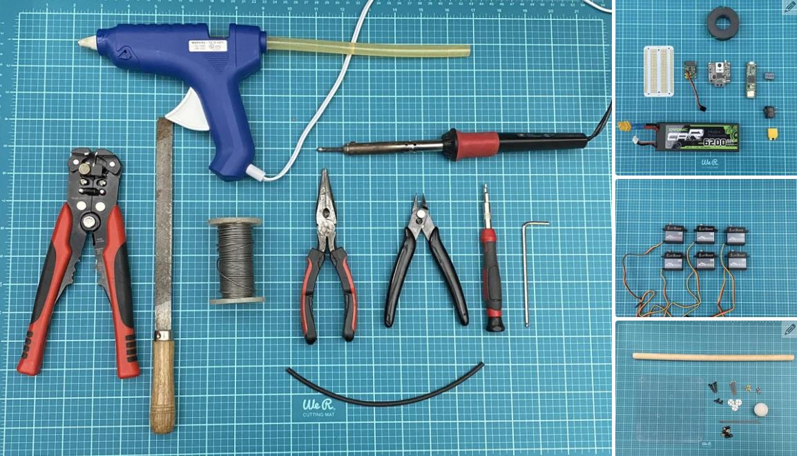 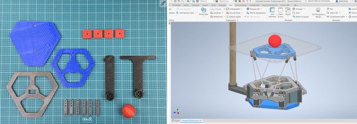 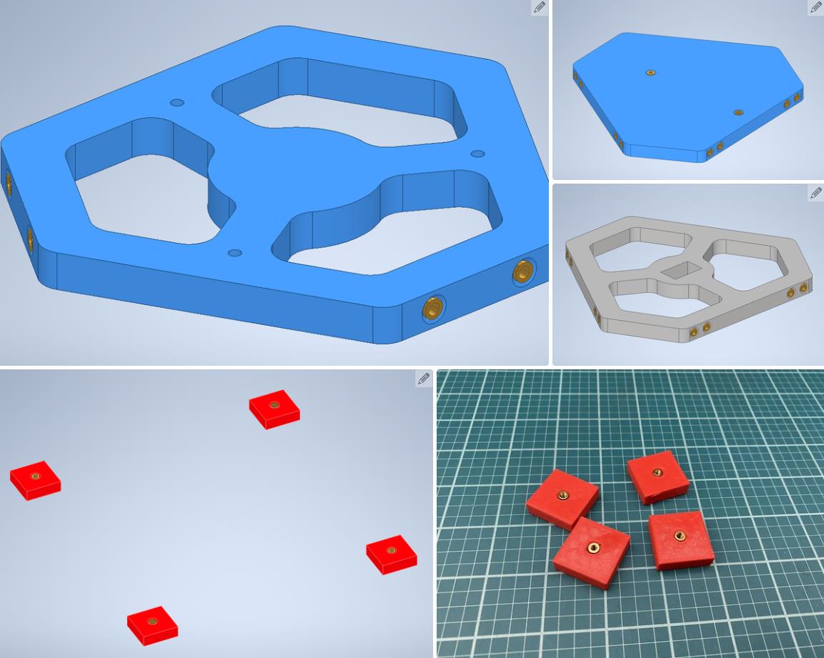 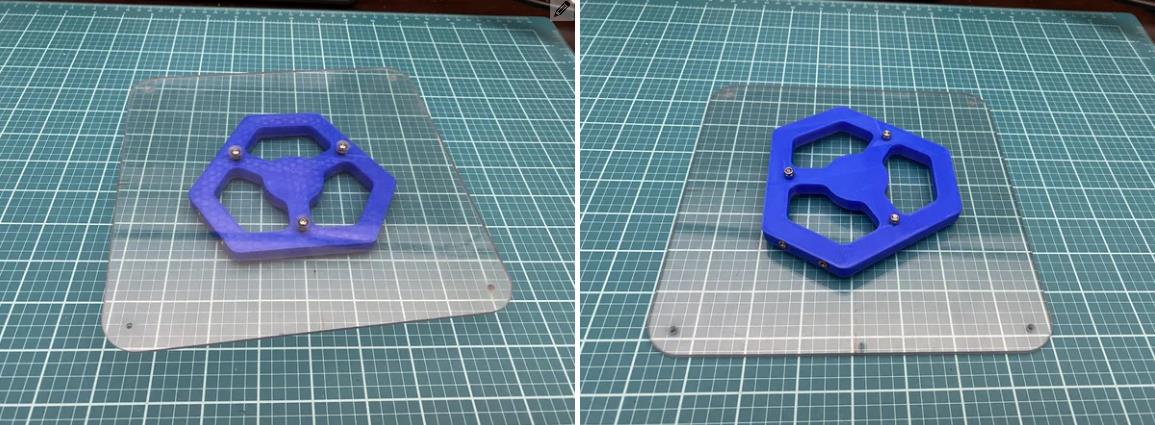 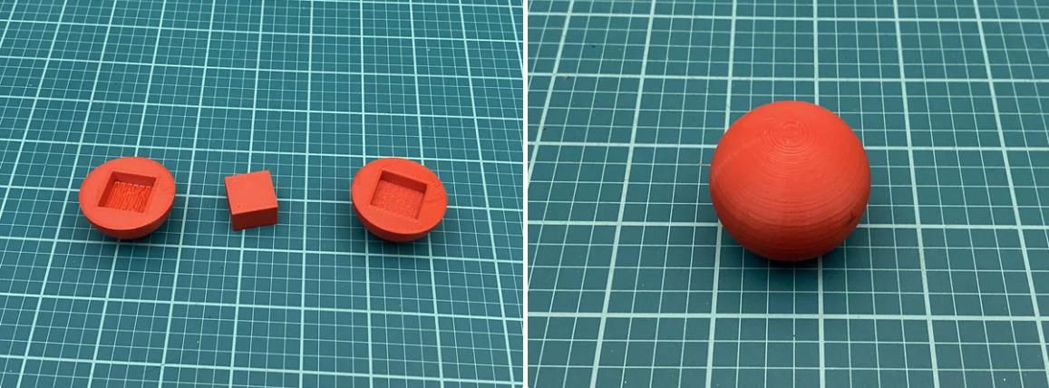 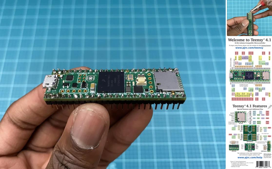 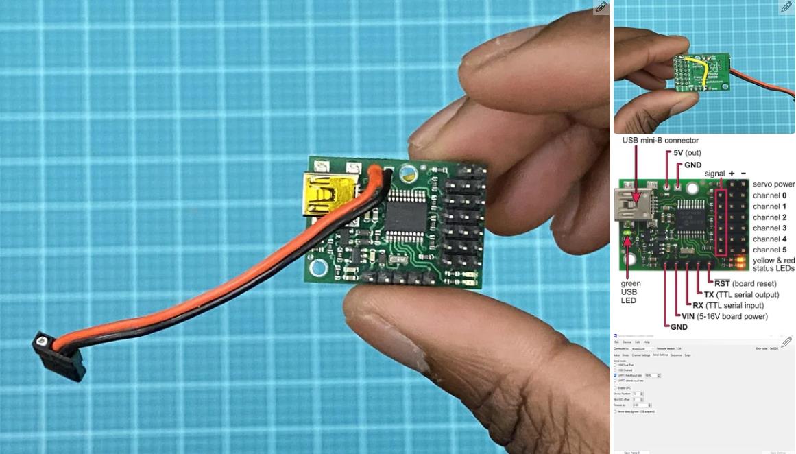 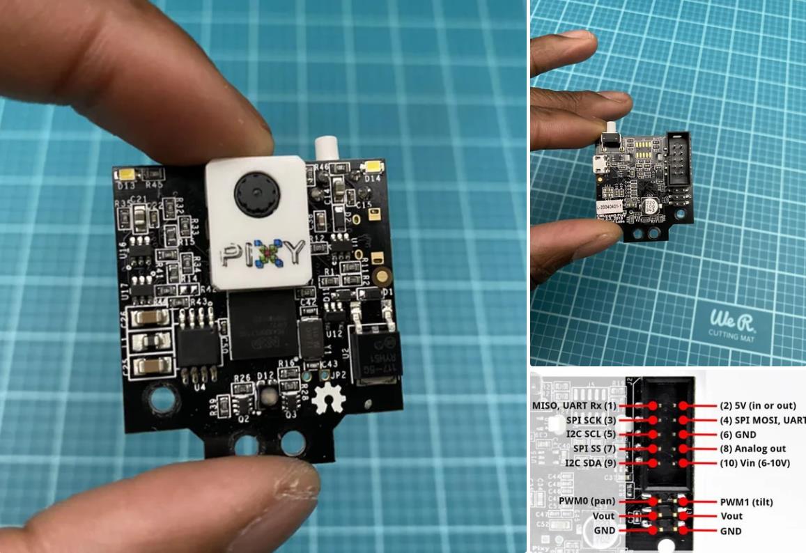 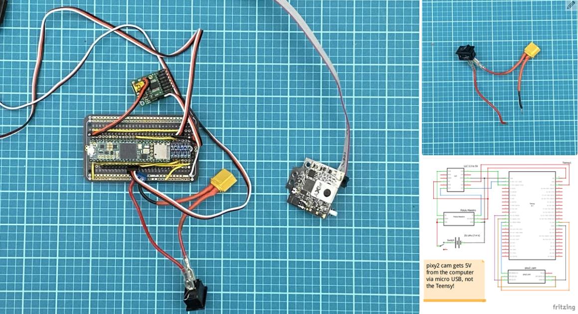 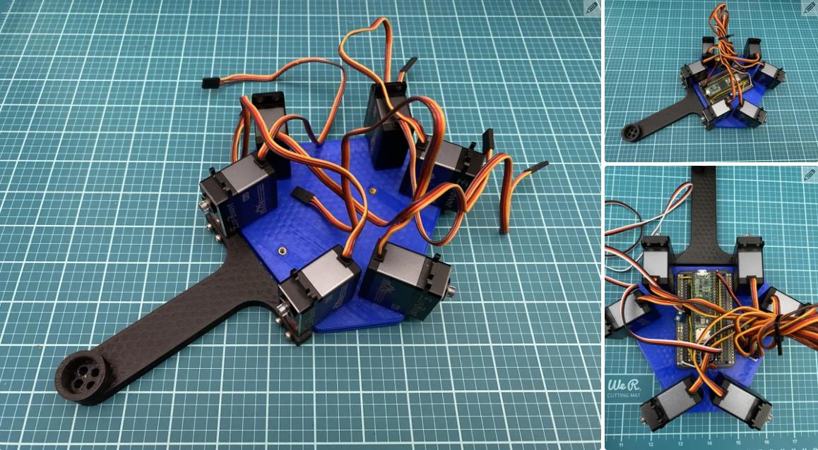 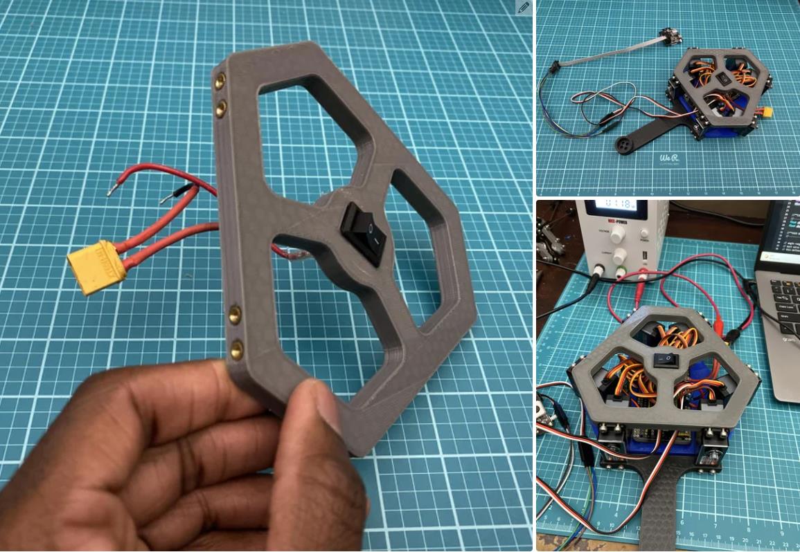 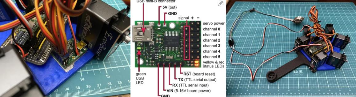 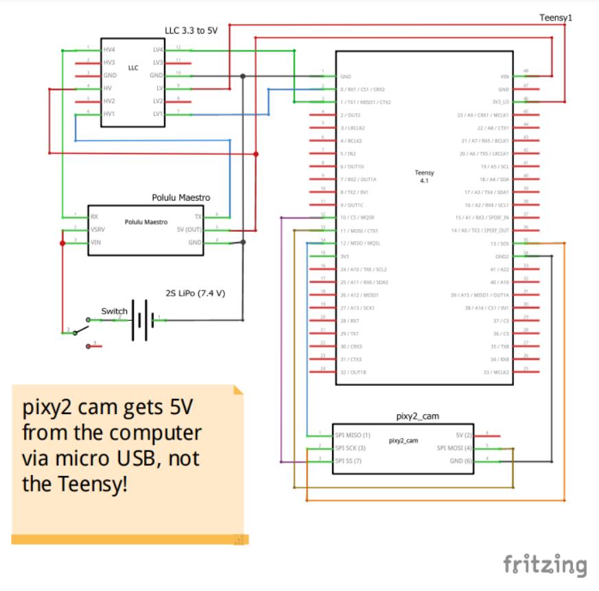 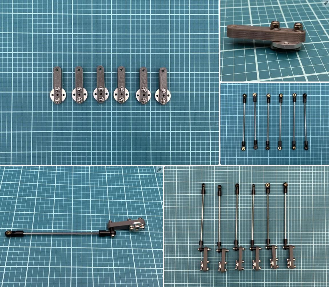 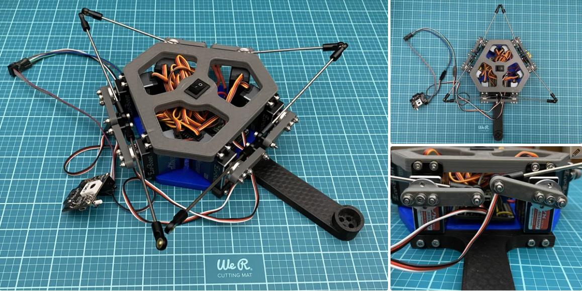 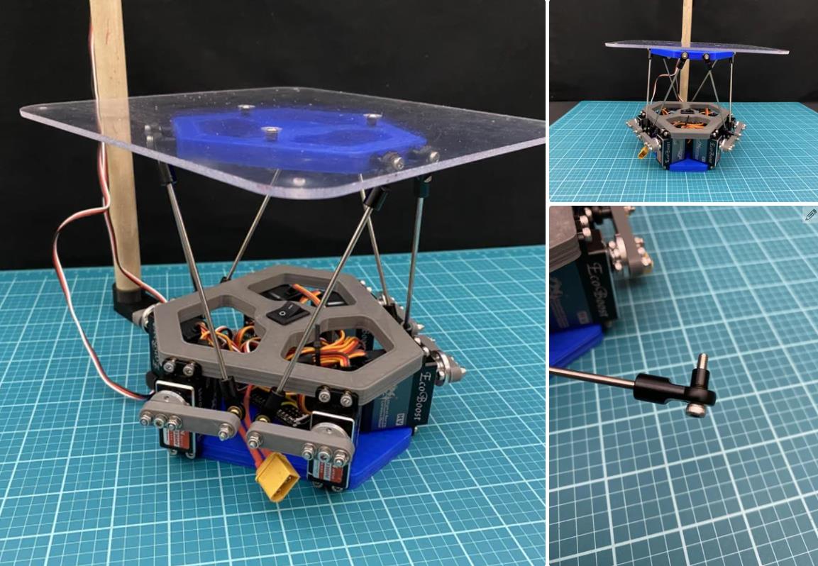 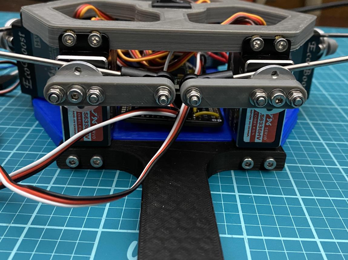 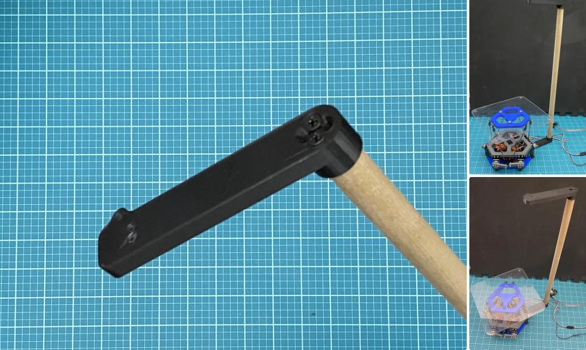 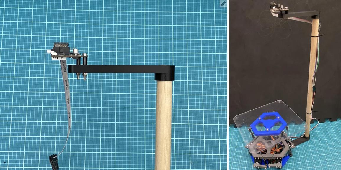 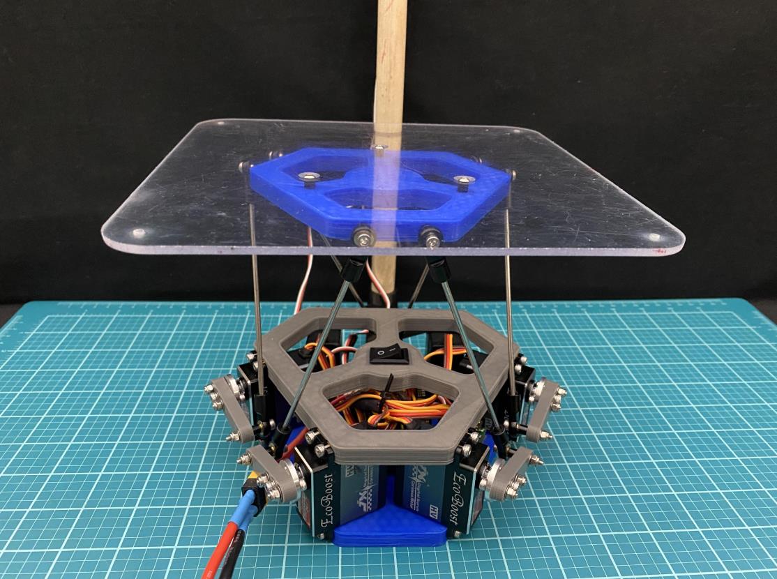 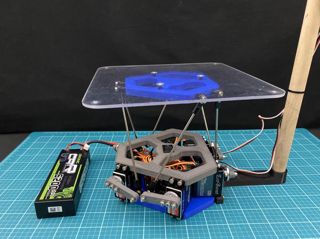 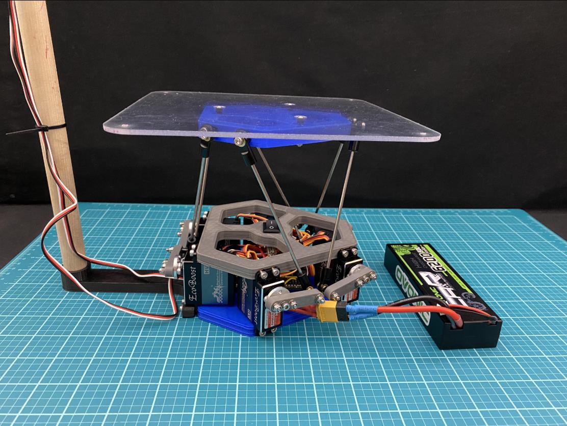 |


项目链接:https://www.instructables.com/Ball-Balancing-Robot/
项目作者:佛罗里达州杰克逊维尔 阿德穆萨
项目视频:https://www.youtube.com/watch?v=kAaYaZcpbLo
项目代码:https://content.instructables.com/FCS/MGTP/LCETD3PY/FCSMGTPLCETD3PY.ino
https://content.instructables.com/FU3/V2LT/LCETD3UI/FU3V2LTLCETD3UI.ino
https://content.instructables.com/FUO/4FMH/LCETD3SB/FUO4FMHLCETD3SB.ino
3D打印文件:https://content.instructables.com/FFX/WSE8/LCDDVD31/FFXWSE8LCDDVD31.stl
https://content.instructables.com/FJZ/LKP3/LCDDVD2X/FJZLKP3LCDDVD2X.stl
https://content.instructables.com/FLI/19MZ/LCDDVD2Y/FLI19MZLCDDVD2Y.stl
[code]/* ****NOTES****
Before using this, go to the Serial Settings
tab in the Maestro Control Center and apply these settings:
Serial mode: UART, fixed baud rate
Baud rate: 9600
CRC disabled
Be sure to click "Apply Settings" after making any changes.
Array Indexes
-------------
a1 = 0
a2 = 1
b1 = 2
b2 = 3
c1 = 4
c2 = 5
range for hz (105, 140)
*/
// libraries
#include "PololuMaestro.h"
#include "math.h"
#include
#define maestroSerial SERIAL_PORT_HARDWARE_OPEN //for teensy
// objects
Pixy2SPI_SS pixy;
MicroMaestro maestro(maestroSerial); // if using the Maestro Micro controller
//**CONSTANTS**
//-------------
float abs_0 = 4000; //ms position of absolute 0 degrees
float abs_90 = 8000; //ms position of absolute 90 degrees
float toDeg = 180 / PI; // radians to degrees conversion factor
int x = 0, y = 1, z = 2; // defines x, y, and z array indexes to be used
String ID[6] = { "a1", "a2", "b1", "b2", "c1", "c2" }; //servo ID's
//**USER DEFINED VALUES**
//----------------------
// angle range for each servo going CCW
// each servo can move from absolute 0 to absolute 90 degrees
// this defines a different range such as 90 to 180 degrees
float range[6][2] = { { -45, 45 }, { 45, -45 }, // a1, a2
{ -45, 45 },
{ 45, -45 }, // b1, b2
{ -45, 45 },
{ 45, -45 } }; // c1, c2
// angle offset value for each servo (should be less than 14 degrees since there are 25 teeth on the servo)
// redefines the position of the lower range of each servo
// Example: a servo with a range [0, 90] and an offset value of 5 would have its new 0 degree position where the old 5 degree position was
float offset[6] = { 0, 0, // channel #0 and channel #1
0, 0, // channel #2 and channel #3
0, 0 }; // channel #4 and channel #5
//**INVERSE KINEMATICS**
//----------------------
// user defined lengths (in mm)
float l0 = 73.025;
float lf = 67.775;
float d1 = 36.8893;
float d2 = 38.1;
float m = 12.7;
float p1 = 31.75;
float p2 = 129;
//calculates normal vectors nab, nac, and nbc for each side of the triangle
float nab[3] = { sqrt(3) * 0.5, -0.5, 0 };
float nac[3] = { sqrt(3) * 0.5, 0.5, 0 };
float nbc[3] = { 0, 1, 0 };
// intermediate variables
float t = (pow(lf, 2) * sqrt(3)) / 2;
float u = sqrt(pow(l0, 2) + pow(d1, 2)) * sin((2 * PI / 3) - atan(l0 / d1)); //(2*pi/3 is 120 degrees)
// calculates points a10, a20, b10, b20, c10, and c20
float a10[3] = { (d2 - u * sqrt(3)) / 2, (-u - d2 * sqrt(3)) / 2, 0 };
float a20[3] = { -a10[x], a10[y], 0 };
float b10[3] = { (u * sqrt(3) + d2) / 2, (d2 * sqrt(3) - u) / 2, 0 };
float b20[3] = { d2, u, 0 };
float c10[3] = { -b20[x], b20[y], 0 };
float c20[3] = { -b10[x], b10[y], 0 };
// calculates vectors, ab, ac, and bc
float ab[3] = { a20[x] - b10[x], a20[y] - b10[y], a20[z] - b10[z] };
float ac[3] = { a10[x] - c20[x], a10[y] - c20[y], a10[z] - c20[z] };
float bc[3] = { b20[x] - c10[x], b20[y] - c10[y], b20[z] - c10[z] };
float theta[6]; //array for calculated theta values a1, a2, b1, b2, c1, c2 respectively
float nz = 1; //nz is predefined
float hz_norm = 118.19374266158451; //normal hz value (at this height all servos are at 0 degrees)
float r_max = 0.25; // max radius of the nx and ny graph when nz = 1
//pixy2 cam
//----------------------
float origin[2] = { 0, 0 }; // X and Y co-ords of the origin
float r_platform = 0; // the distance from the center of the platform to the corner of the platform seen from the pixy2 cam
float ball[2]; // X and Y co-ords of the ball
// PID
//----------------------
float error[2]; // error of the ball
float error_prev[2]; // previous error value used to calculate derivative. Derivative = (error-previous_error)/(change in time)
float deriv[2]; // derivative of the error
float deriv_prev[2]; // previous derivative value
float kp = 6e-4; // proportional constant
float kd = 0.56; // derivative constant
float out[2]; // output values (nx and ny)
float time_i; // initial time
float time_f; // final time
float time; //change in time
void setup() {
Serial.begin(115200);
maestroSerial.begin(9600);
pixy.init();
}
void loop() {
findBall(); // finds the location of the ball
if (ball[x] == 4004 && ball[y] == 4004) {
// sees if ball position (x and y) is 4004, if so then the ball is not detected and platform should be in home position
InverseKinematics(0, 0, hz_norm, 0, 0, 0); //hx, hy, hz, nx, ny, ax
moveServos(20, 20);
} else {
PD(); // calculates the proportional and derivative terms and outputs them to the platform
}
//Serial.println((String)"BALL LOCATION: [" + ball[x]+", "+ball[y]+"]"); //prints location of the ball
//Serial.println((String)"OUTPUT: [" + out[x]+", "+ out[y]+"]"); //prints the output values
}
//Functions
void moveServo(int i, float pos, int spd, int acc) { //moves servo i to an input position at a certain speed and acceleration value
pos = pos + offset[i]; //adds offset amount to the input position
pos = map(pos, range[i][0], range[i][1], abs_0, abs_90); //converts input pos to ms position
maestro.setSpeed(i, spd); //sets input speed to servo i
maestro.setAcceleration(i, spd); //sets input acceleration to servo i
maestro.setTarget(i, pos); //drives motor to calculated position
}
void moveServos(int spd, int acc) { //moves servos to their calculated positions at a certain speed and acceleration value
float pos;
for (int i = 0; i < 6; i++) {
maestro.setSpeed(i, spd); //sets input speed to servo i
maestro.setAcceleration(i, acc); //sets input acceleration to servo i
pos = theta[i] + offset[i]; //adds offset amount to the calculated angle
pos = map(pos, range[i][0], range[i][1], abs_0, abs_90); //converts input pos to ms position
maestro.setTarget(i, pos); //drives motor to calculated position
}
}
void stop() { //ends the program and stops all of the servos
for (int i = 0; i < 6; i++) {
maestro.setTarget(i, 0); //stops servo i
}
while (1) {}
}
void findBall() { // find the location of the ball using the pixy2 cam
// grab blocks!
pixy.ccc.getBlocks();
// If there is 1 ball detected then collect and print the data
if (pixy.ccc.numBlocks == 1) {
//sets current X and Y co-ords
ball[x] = pixy.ccc.blocks[0].m_x; // absolute X location of the ball
ball[y] = pixy.ccc.blocks[0].m_y; // absolute Y location of the ball
}
// If there are multiple balls detected, then print so
else if (pixy.ccc.numBlocks > 1) {
Serial.println("MULTIPLE BALLS DETECTED");
ball[x] = 4004; // X component of the ball
ball[y] = 4004; // Y component of the ball
}
// If there is no ball detected, then print so
else {
//Serial.println("NO BALL DETECTED");
ball[x] = 4004; // X component of the ball
ball[y] = 4004; // Y component of the ball
}
}
void PD() { // calculates the Proportional and Derivative values and moves the servos
// calculates the error of the ball
// the error is the difference of the location of the center of the ball and the center of the platform
// it is essentially a vector pointing from the center of the platform to the center of the ball
error[x] = origin[x] - ball[x]; // x component of error
error[y] = ball[y] - origin[y]; // y component of error
time_f = millis(); // sets final time
time = time_f - time_i; // change in time
time_i = millis();
// sets initial time
deriv[x] = (error[x] - error_prev[x]) / time; // x component of derivative
deriv[y] = (error[y] - error_prev[y]) / time; // y component of derivative
// checks if derivative is NaN or INF. If so, set to zero
if (isnan(deriv[x]) || isinf(deriv[x])) { // x component of derivative
deriv[x] = 0;
}
if (isnan(deriv[y]) || isinf(deriv[y])) { // y component of derivative
deriv[y] = 0;
}
// sets previous error to current error
error_prev[x] = error[x]; // x component of previous error
error_prev[y] = error[y]; // x component of previous error
float r_ball = sqrt(pow(error[x], 2) + pow(error[y], 2)); // calculates the distance from the center of the platfrom to the ball
if (r_ball > r_platform) {
// checks to see if the platform should be moved to the home position
// checks if the ball is on the platform by comparing r_ball and r_platform. If r_ball is greater than r_platform, the ball is off the platform and the platform should be in the home position
InverseKinematics(0, 0, hz_norm, 0, 0, 0); //hx, hy, hz, nx, ny, ax
moveServos(20, 20);
}
else { //if the ball should not be in the home position then calculate PD outputs
// output values
out[x] = (error[x] * kp) + (deriv[x] * kd); // calculates output x by adding proportional*kp and derivative*kd terms
out[y] = (error[y] * kp) + (deriv[y] * kd); // calculates output y by adding proportional*kp and derivative*kd terms
// error prevention
float r_out = sqrt(pow(out[x], 2) + pow(out[y], 2)); //calculates magnitude of the out vector
if (r_out > r_max) { // if the magnitude of the out vector is greater than r_max, then scale the out vector to have a magnitude of r
out[x] = out[x] * (r_max / r_out);
out[y] = out[y] * (r_max / r_out);
}
//move platform
InverseKinematics(0, 0, hz_norm, out[x], out[y], 0); //hx, hy, hz, nx, ny, ax
moveServos(0, 0);
}
}
void InverseKinematics(float hx, float hy, float hz, float nx, float ny, float ax) { // calculates theta values given hx, hy, hz, nx, ny, and ax (nz = 1 always)
//define vectors and points
float a[3] = { ax, 0, 0 }, a1f[3], a2f[3];
float b[3], b1f[3], b2f[3];
float c[3], c1f[3], c2f[3];
float n[3] = { nx, ny, nz }; // defines normal vector
n[x] = nx / mag(n);
n[y] = ny / mag(n);
n[z] = nz / mag(n); // converts vector 'n' to a unit vector
float h[3] = { hx, hy, hz }; // defined point h (center point of platform)
// **STAGE 1 CALCULATIONS**
//-------------------------
// in regards to e, g, and k indexes 0, 1, and 2 are a, b, and c respectively
float e[3], g[3], k[3];
// af components
e[0] = a[x] - h[x]; // 'ea'
a[z] = ((n[y] * sqrt(pow(lf, 2) * (1 - pow(n[x], 2)) - pow(e[0], 2)) - n[z] * n[x] * e[0]) / (1 - pow(n[x], 2))) + h[z]; // 'az'
g[0] = a[z] - h[z]; // calculates 'ga'
a[y] = h[y] - sqrt(pow(lf, 2) - pow(g[0], 2) - pow(e[0], 2)); // 'ay'
k[0] = a[y] - h[y]; // 'ka'
float w = sqrt(3) * (n[x] * g[0] - n[z] * e[0]); // intermediate variable
// bf components
b[y] = h[y] + ((sqrt(pow(w, 2) - 3 * pow(lf, 2) * (1 - pow(n[y], 2)) + pow(2 * k[0], 2)) - w) / 2); // 'by'
k[1] = b[y] - h[y]; // 'kb'
b[x] = ((e[0] * k[1] - n[z] * t) / k[0]) + h[x]; // 'bx'
e[1] = b[x] - h[x]; // 'eb'
b[z] = ((n[x] * t + g[0] * k[1]) / k[0]) + h[z]; //'bz'
g[1] = b[z] - h[z]; // 'gb'
// cf components
c[y] = h[y] + ((w + sqrt(pow(w, 2) - 3 * pow(lf, 2) * (1 - pow(n[y], 2)) + pow(2 * k[0], 2))) / 2); // 'cy'
k[2] = c[y] - h[y]; // 'kc'
c[x] = ((e[0] * k[2] + n[z] * t) / k[0]) + h[x]; // 'cx'
e[2] = c[x] - h[x]; // 'ec'
c[z] = ((g[0] * k[2] - n[x] * t) / k[0]) + h[z]; // 'cz'
g[2] = c[z] - h[z]; // 'gc'
// STAGE 2 CALCULATIONS
//---------------------
// a1
a1f[x] = a[x] + (m / lf) * (n[z] * k[0] - n[y] * g[0]); // a1fx
if (e[0] == 0) { //if e[0] is 0 then there will be a divide by zero error
a1f[y] = a[y]; // a1fy
a1f[z] = a[z]; // a1fz
} else {
a1f[y] = a[y] + ((a1f[x] - a[x]) * k[0] - n[z] * lf * m) / e[0]; // a1fy
a1f[z] = a[z] + (n[y] * lf * m + (a1f[x] - a[x]) * g[0]) / e[0]; // a1fz
}
float a1[3] = { a1f[x] - a10[x], a1f[y] - a10[y], a1f[z] - a10[z] }; // vector 'a1'
// a2
a2f[x] = 2 * a[x] - a1f[x]; // a2fx
a2f[y] = 2 * a[y] - a1f[y]; // a2fy
a2f[z] = 2 * a[z] - a1f[z]; // a2fz
float a2[3] = { a2f[x] - a20[x], a2f[y] - a20[y], a2f[z] - a20[z] }; // vector 'a2'
// b1
b1f[x] = b[x] + (m / lf) * (n[z] * k[1] - n[y] * g[1]); // b1fx
b1f[y] = b[y] + ((b1f[x] - b[x]) * k[1] - n[z] * lf * m) / e[1]; // b1fy
b1f[z] = b[z] + (n[y] * lf * m + (b1f[x] - b[x]) * g[1]) / e[1]; // b1fz
float b1[3] = { b1f[x] - b10[x], b1f[y] - b10[y], b1f[z] - b10[z] }; // vector 'b1'
// b2
b2f[x] = 2 * b[x] - b1f[x]; // b2fx
b2f[y] = 2 * b[y] - b1f[y]; // b2fy
b2f[z] = 2 * b[z] - b1f[z]; // b2fz
float b2[3] = { b2f[x] - b20[x], b2f[y] - b20[y], b2f[z] - b20[z] }; // vector 'b2'
// c1
c1f[x] = c[x] + (m / lf) * (n[z] * k[2] - n[y] * g[2]); // c1fx
c1f[y] = c[y] + ((c1f[x] - c[x]) * k[2] - n[z] * lf * m) / e[2]; // c1fy
c1f[z] = c[z] + (n[y] * lf * m + (c1f[x] - c[x]) * g[2]) / e[2]; // c1fz
float c1[3] = { c1f[x] - c10[x], c1f[y] - c10[y], c1f[z] - c10[z] }; // vector 'c1'
// c2
c2f[x] = 2 * c[x] - c1f[x]; // c2fx
c2f[y] = 2 * c[y] - c1f[y]; // c2fy
c2f[z] = 2 * c[z] - c1f[z]; // c2fzSerial.println("-----------------------");
float c2[3] = { c2f[x] - c20[x], c2f[y] - c20[y], c2f[z] - c20[z] }; // vector 'c2'
//**STAGE 3 CALCULATIONS**
//------------------------
// theta_a1
float a1s[3] = { nac[x] * dot(a1, nac), nac[y] * dot(a1, nac), nac[z] * dot(a1, nac) }; // vector 'a1s'
float mag_a1s = mag(a1s); // magnitude of vector 'a1s'
float a1_proj[3] = { a1[x] - a1s[x], a1[y] - a1s[y], a1[z] - a1s[z] }; // projection of vector 'a1' onto the ac plane
float mag_a1_proj = mag(a1_proj); // magnitude of vector 'a1' projected on the ac plane
float mag_p2a1 = sqrt(pow(p2, 2) - pow(mag_a1s, 2)); // magnitude of link p2 projected on the ac plane
theta[0] = acos(-dot(a1_proj, ac) / (2 * d2 * mag_a1_proj)); // theta a1
theta[0] = (theta[0] - acos((pow(mag_a1_proj, 2) + pow(p1, 2) - pow(mag_p2a1, 2)) / (2 * mag_a1_proj * p1))) * toDeg; // theta a1 continued calculation
// theta_a2
float a2s[3] = { nab[x] * dot(a2, nab), nab[y] * dot(a2, nab), nab[z] * dot(a2, nab) }; // vector 'a2s'
float mag_a2s = mag(a2s); // magnitude of vector 'a2s'
float a2_proj[3] = { a2[x] - a2s[x], a2[y] - a2s[y], a2[z] - a2s[z] }; // projection of vector 'a2' onto the ab plane
float mag_a2_proj = mag(a2_proj); // magnitude of vector 'a2' projected on the ab plane
float mag_p2a2 = sqrt(pow(p2, 2) - pow(mag_a2s, 2)); // magnitude of link p2 projected on the ab plane
theta[1] = acos(-dot(a2_proj, ab) / (2 * d2 * mag_a2_proj)); // theta a2
theta[1] = (theta[1] - acos((pow(mag_a2_proj, 2) + pow(p1, 2) - pow(mag_p2a2, 2)) / (2 * mag_a2_proj * p1))) * toDeg; // theta a2 continued calculation
// theta_b1
float b1s[3] = { nab[x] * dot(b1, nab), nab[y] * dot(b1, nab), nab[z] * dot(b1, nab) }; // vector 'b1s'
float mag_b1s = mag(b1s); // magnitude of vector 'b1s'
float b1_proj[3] = { b1[x] - b1s[x], b1[y] - b1s[y], b1[z] - b1s[z] }; // projection of vector 'b1' onto the ab plane
float mag_b1_proj = mag(b1_proj); // magnitude of vector 'b1' projected on the ab plane
float mag_p2b1 = sqrt(pow(p2, 2) - pow(mag_b1s, 2)); // magnitude of link p2 projected on the ab plane
theta[2] = acos(dot(b1_proj, ab) / (2 * d2 * mag_b1_proj)); // theta b1
theta[2] = (theta[2] - acos((pow(mag_b1_proj, 2) + pow(p1, 2) - pow(mag_p2b1, 2)) / (2 * mag_b1_proj * p1))) * toDeg; // theta b1 continued calculation
// theta_b2
float b2s[3] = { nbc[x] * dot(b2, nbc), nbc[y] * dot(b2, nbc), nbc[z] * dot(b2, nbc) }; // vector 'b2s'
float mag_b2s = mag(b2s); // magnitude of vector 'b2s'
float b2_proj[3] = { b2[x] - b2s[x], b2[y] - b2s[y], b2[z] - b2s[z] }; // projection of vector 'b2' onto the bc plane
float mag_b2_proj = mag(b2_proj); // magnitude of vector 'b2' projected on the bc plane
float mag_p2b2 = sqrt(pow(p2, 2) - pow(mag_b2s, 2)); // magnitude of link p2 projected on the bc plane
theta[3] = acos(-dot(b2_proj, bc) / (2 * d2 * mag_b2_proj)); // theta b2
theta[3] = (theta[3] - acos((pow(mag_b2_proj, 2) + pow(p1, 2) - pow(mag_p2b2, 2)) / (2 * mag_b2_proj * p1))) * toDeg; // theta b2 continued calculation
// theta_c1
float c1s[3] = { nbc[x] * dot(c1, nbc), nbc[y] * dot(c1, nbc), nbc[z] * dot(c1, nbc) }; // vector 'c1s'
float mag_c1s = mag(c1s); // magnitude of vector 'c1s'
float c1_proj[3] = { c1[x] - c1s[x], c1[y] - c1s[y], c1[z] - c1s[z] }; // projection of vector 'c1' onto the bc plane
float mag_c1_proj = mag(c1_proj); // magnitude of vector 'c1' projected on the bc plane
float mag_p2c1 = sqrt(pow(p2, 2) - pow(mag_c1s, 2)); // magnitude of link p2 projected on the bc plane
theta[4] = acos(dot(c1_proj, bc) / (2 * d2 * mag_c1_proj)); // theta c1
theta[4] = (theta[4] - acos((pow(mag_c1_proj, 2) + pow(p1, 2) - pow(mag_p2c1, 2)) / (2 * mag_c1_proj * p1))) * toDeg; // theta c1 continued calculation
//theta_c2
float c2s[3] = { nac[x] * dot(c2, nac), nac[y] * dot(c2, nac), nac[z] * dot(c2, nac) }; // vector 'c2s'
float mag_c2s = mag(c2s); // magnitude of vector 'c2s'
float c2_proj[3] = { c2[x] - c2s[x], c2[y] - c2s[y], c2[z] - c2s[z] }; // projection of vector 'c2' onto the ac plane
float mag_c2_proj = mag(c2_proj); // magnitude of vector 'c2' projected on the ac plane
float mag_p2c2 = sqrt(pow(p2, 2) - pow(mag_c2s, 2)); // magnitude of link p2 projected on the ac plane
theta[5] = acos(dot(c2_proj, ac) / (2 * d2 * mag_c2_proj)); // theta c2
theta[5] = (theta[5] - acos((pow(mag_c2_proj, 2) + pow(p1, 2) - pow(mag_p2c2, 2)) / (2 * mag_c2_proj * p1))) * toDeg; // theta c2 continued calculation
for (int i = 0; i < 6; i++) { //checks for errors to see if theta values are between -40 and 40 degrees and if they are real numbers
//Serial.print(String("theta "+ID[i]+": ")); // prints servo ID
//Serial.println(theta[i], 6); // prints theta value
if (abs(theta[i]) > 40) {
Serial.println("ERROR: CURRENT VALUES EXCEED ANGLE RANGE");
stop();
}
if (isnan(theta[i])) {
Serial.println("ERROR: CURRENT VALUES CANNOT PHYSICALLY BE EXECUTED");
stop();
}
}
}
float mag(float array[]) { //finds the magnitude of an array of size 3
float mag = 0;
for (int i = 0; i < 3; i++) {
mag = mag + pow(array[i], 2); //adds component i of array squared
}
mag = sqrt(mag);
return mag;
}
float dot(float array1[], float array2[]) { //calculates the dot product of two arrays
return array1[0] * array2[0] + array1[1] * array2[1] + array1[2] * array2[2];
}[/code]