

【Arduino 动手做】实现残障人对智能家居无接触便捷控制
2025-07-252226
AI 快速预览详细
Air Clicker是一款基于Arduino的手势控制手套,旨在帮助残障人士通过手势和语音命令实现对智能家居设备的非接触式控制。该系统包括门摄像头、继电器控制器和UniHiker仪表板,使用户能够独立执行任务,如查看门口情况、解锁门或控制家用电器。这项创新技术提升了残障人士的独立生活能力,减少了对他人的依赖。
|
使用基于手势的创新技术,使残疾人能够对智能家居设备进行非接触式控制。 智能家居辅助系统旨在通过赋予身体残疾者独立控制家庭设备的能力来增强他们的能力。这个项目的灵感来自于我对残疾人生活的研究。我发现的一个共同主题是减少日常任务对他人的依赖的强烈愿望。 在我的研究过程中,我看到了一段视频,视频中一名截瘫男子失去了手指。在视频中,他演示了如何在病情不佳的情况下使用手机。这引起了我的共鸣,并促使我开发一种设备,可以让他和其他处于类似情况的人更轻松地使用手机。 结果是 Air Clicker——一款像手套一样贴合的可穿戴鼠标。鼠标指针沿手部方向移动,单击是通过语音命令实现的。该设备可以通过USB连接到PC、手机或平板电脑,从而扩展其跨多个平台的可用性。 为了解决依赖性问题,Air Clicker 简化了与手机和 PC 的交互,从而促进了通过这些接口控制智能家居设备。这项创新可以帮助残疾人独立执行任务,例如查看门口的人、解锁门或打开和关闭电器。 基于这个概念,我扩展了该项目,包括一个完整的智能家居系统,恰如其分地命名为 Smart Home Assist。除空气答题器外,该系统还包括三个主要组件: 门摄像头:一种门铃摄像头,可在按下按钮时捕获图像并将其发送给房主。 继电器控制器:管理各种家用电器和电子产品(例如灯泡和风扇)的设备。 UniHiker 仪表板:智能家居系统的用户界面,允许用户控制设备并查看来自摄像头的图像。 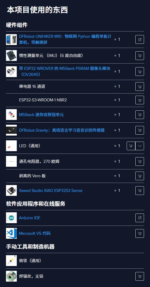 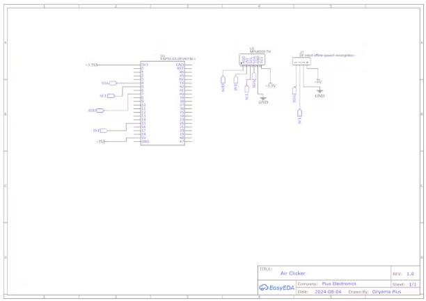 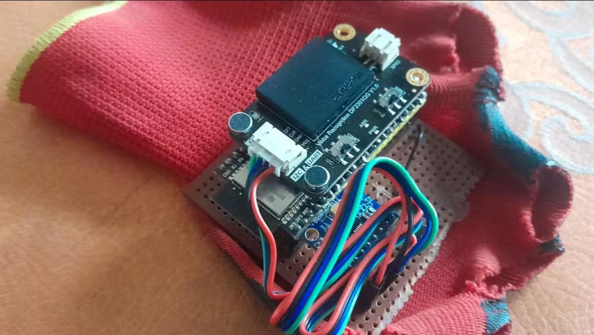 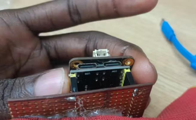 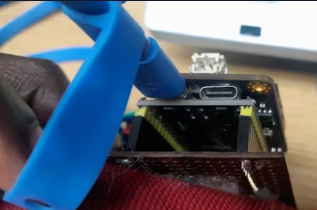 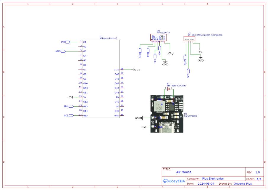 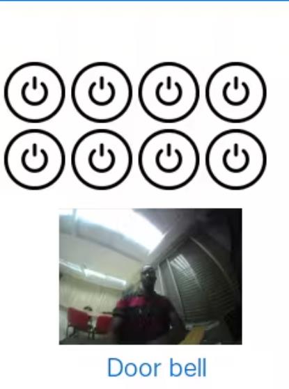 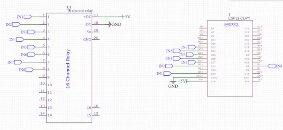 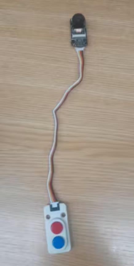 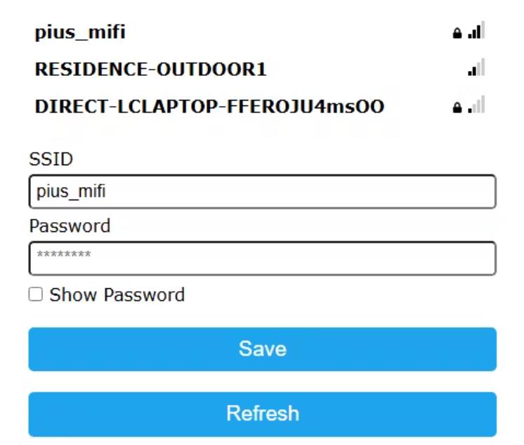 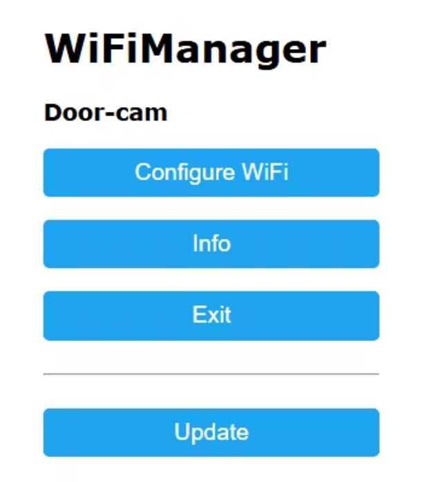 |

项目链接:https://www.hackster.io/pius4109/smart-assist-home-smart-home-for-disable-people-e31e34
项目作者:皮乌斯·奥涅马·恩杜库
项目视频 :
https://www.youtube.com/watch?v=-BtSs9keBJQ
https://www.youtube.com/watch?v=kl-4lKPXUrc
项目代码:https://github.com/Pius171/Unihiker-Smart-Home
[code]from flask import Flask, request, redirect, url_for, send_from_directory
import os
from unihiker import GUI # Import the package
from dataclasses import dataclass
import time
from pinpong.board import Board, Pin, Tone # Import the Board, Pin, and Tone modules from the pinpong.board package
import requests
debug = True # allows me to turn of some print functions
Board().begin("UNIHIKER") # Initialize the board, choose the board type and port number (auto-detection if not specified)
gui = GUI() # Instantiate the GUI class
#esp32 node url
node_url= "http://192.168.0.134/pin"
@dataclass
class button:
name:str #button name
state: bool #button state
image: gui #button image
cor: list #coordinate of the button
def switch_clicked(button):
gui.remove(button.image)
if button.state:
button.image= gui.draw_image(x=button.cor[0], y=button.cor[1], w=50, h=50, image='/root/my_codes/smart_home/images/power-button-off.png', onclick=lambda: switch_clicked(button))
else:
button.image= gui.draw_image(x=button.cor[0], y=button.cor[1], w=50, h=50, image='/root/my_codes/smart_home/images/power-button-on.png', onclick=lambda: switch_clicked(button))
button.state=not button.state
data = button.name+ (str(1) if button.state else str(0))
response = requests.post(node_url, data)
if debug:
print(response.status_code)
print(response.text)
print(button.name,button.state)
tone = Tone(Pin(Pin.P26)) # Create a Tone object with Pin.P26 for analog output
tone.freq(200) # Set the frequency to 200 for the tone playback
# button are named from 0-7
button1 = button(name="0",state=0,image=gui.draw_image(x=5, y=50, w=50, h=50, image='/root/my_codes/smart_home/images/power-button-off.png', onclick=lambda: switch_clicked(button1)),cor=[5,50])
button2 = button(name="1", state=0, image=gui.draw_image(x=60, y=50, w=50, h=50, image='/root/my_codes/smart_home/images/power-button-off.png', onclick=lambda: switch_clicked(button2)),cor=[60,50])
button3 = button(name="2", state=0, image=gui.draw_image(x=115, y=50, w=50, h=50, image='/root/my_codes/smart_home/images/power-button-off.png', onclick=lambda: switch_clicked(button3)),cor=[115,50])
button4 = button(name="3", state=0, image=gui.draw_image(x=170, y=50, w=50, h=50, image='/root/my_codes/smart_home/images/power-button-off.png', onclick=lambda: switch_clicked(button4)),cor=[170,50])
button5 = button(name="4", state=0, image=gui.draw_image(x=5, y=105, w=50, h=50, image='/root/my_codes/smart_home/images/power-button-off.png', onclick=lambda: switch_clicked(button5)),cor=[5,105])
button6 = button(name="5", state=0, image=gui.draw_image(x=60, y=105, w=50, h=50, image='/root/my_codes/smart_home/images/power-button-off.png', onclick=lambda: switch_clicked(button6)),cor=[60,105])
button7 = button(name="6", state=0, image=gui.draw_image(x=115, y=105, w=50, h=50, image='/root/my_codes/smart_home/images/power-button-off.png', onclick=lambda: switch_clicked(button7)),cor=[115,105])
button8 = button(name="7", state=0, image=gui.draw_image(x=170, y=105, w=50, h=50, image='/root/my_codes/smart_home/images/power-button-off.png', onclick=lambda: switch_clicked(button8)),cor=[170,105])
#image of person at doorbell
door_bell= gui.draw_image(x=30, y=170, w=180, h=180, image='/root/my_codes/smart_home/images/person.jpg')
door_cam_text =gui.draw_text(text="Door bell",origin="center",x=130,y=300,color="#0066CC")
app = Flask(__name__)
# Define the folder to store uploaded files
UPLOAD_FOLDER = 'uploads'
if not os.path.exists(UPLOAD_FOLDER):
os.makedirs(UPLOAD_FOLDER)
app.config['UPLOAD_FOLDER'] = UPLOAD_FOLDER
app.config['MAX_CONTENT_LENGTH'] = 16 * 1024 * 1024 # Max upload size is 16MB
@app.route('/')
def index():
return '''
Upload a file
'''
@app.route('/upload', methods=['POST'])
def upload_file():
global door_bell
if 'file' not in request.files:
return 'No file part', 400
file = request.files['file']
if file.filename == '':
return 'No selected file', 400
if file:
filename = file.filename
filepath = os.path.join(app.config['UPLOAD_FOLDER'], filename)
gui.remove(door_bell)
file.save(filepath)
door_bell= gui.draw_image(x=50, y=170, w=150, h=150, image=filepath)
tone.on() # Turn on the tone output
time.sleep(1.5) # Delay for 1.5 seconds
tone.off() # Turn off the tone output
file.close()
os.remove(filepath)
return f'File uploaded successfully: {filename}', 200
@app.route('/uploads/
def uploaded_file(filename):
return send_from_directory(app.config['UPLOAD_FOLDER'], filename)
if __name__ == '__main__':
app.run(host='0.0.0.0', port=5001, debug=True)[/code]
[code]/*
@brief
The code receives http request from a server containing a message.
based on the content of the message it turns on certain GPIO's
connected to relays.
*/
#include
#include
#include
#include
#include
WebServer server(80);
const int led = 13;
const int outputs[] = { 13, 14, 27, 26, 5, 33, 32, 4 };
void handleNotFound() {
digitalWrite(led, 1);
String message = "File Not Found\n\n";
message += "URI: ";
message += server.uri();
message += "\nMethod: ";
message += (server.method() == HTTP_GET) ? "GET" : "POST";
message += "\nArguments: ";
message += server.args();
message += "\n";
for (uint8_t i = 0; i < server.args(); i++) {
message += " " + server.argName(i) + ": " + server.arg(i) + "\n";
}
server.send(404, "text/plain", message);
}
void setup(void) {
for (int i = 0; i < 8; i++) {
pinMode(outputs[i], OUTPUT);
digitalWrite(outputs[i],1);
}
Serial.begin(115200);
WiFi.mode(WIFI_STA);
WiFiManager wm;
bool res;
// res = wm.autoConnect(); // auto generated AP name from chipid
res = wm.autoConnect("Relay Controller"); // anonymous ap
//res = wm.autoConnect("AutoConnectAP","password"); // password protected ap
if (!res) {
Serial.println("Failed to connect");
// ESP.restart();
} else {
//if you get here you have connected to the WiFi
Serial.println("connected...yeey :)");
}
server.on("/pin", []() {
String response = server.arg("plain");
//Serial.println(response);
Serial.print("index: ");
Serial.println(response[0]);
Serial.print("state: ");
Serial.println(response[1]);
int pinIndex= response[0] - '0';
int pinState = response[1] - '0';
digitalWrite(outputs[pinIndex],!pinState); //server.send(200, "text/plain", "received with thanks");
});
server.onNotFound(handleNotFound);
server.begin();
Serial.println("HTTP server started");
}
void loop(void) {
server.handleClient();
delay(2); //allow the cpu to switch to other tasks
}[/code]
调试
如果 LED 不亮,则表示与服务器的连接存在问题。它可能是以下之一
相机与服务器不在同一个 WiFi 网络上
服务器未运行
用于创建网络的路由器未打开或不可用
相机在连接到路由器时遇到问题
如果 LED 亮起并且图像未发送给独行者,则相机存在问题。问题可能是以下任何一种
您使用的相机型号与我不同
如果您与我使用相同的相机,您可能在板选项中选择了错误的板。板应该 ve M5unitcam
告诉用户记下 unihiker IP 地址 为 Unihiker 智能家居的所有组件提供单独的自述文件
[code]/* Author: Pius Onyema Ndukwu
code adapted from Rui santos tutorial on RandomNerd Tutorials
Rui Santos
Complete project details at:
https://RandomNerdTutorials.com/esp32-cam-http-post-php-arduino/
https://RandomNerdTutorials.com/esp32-cam-post-image-photo-server/
Permission is hereby granted, free of charge, to any person obtaining a copy
of this software and associated documentation files.
The above copyright notice and this permission notice shall be included in all
copies or substantial portions of the Software.
*/
#include
#include
#include "soc/soc.h"
#include "soc/rtc_cntl_reg.h"
#include "esp_camera.h"
#include
bool connectedFlag = true;
String serverName = "192.168.0.187"; // REPLACE with flask server IP ADDRESS running on unihiker
String serverPath = "/upload"; // The default serverPath
const int serverPort = 5001; // unihiker flask server port
WiFiClient client;
// board: m5unitcam
// CAMERA_MODEL_M5STACK_V2_PSRAM
#define PWDN_GPIO_NUM -1
#define RESET_GPIO_NUM 15
#define XCLK_GPIO_NUM 27
#define SIOD_GPIO_NUM 22
#define SIOC_GPIO_NUM 23
#define Y9_GPIO_NUM 19
#define Y8_GPIO_NUM 36
#define Y7_GPIO_NUM 18
#define Y6_GPIO_NUM 39
#define Y5_GPIO_NUM 5
#define Y4_GPIO_NUM 34
#define Y3_GPIO_NUM 35
#define Y2_GPIO_NUM 32
#define VSYNC_GPIO_NUM 25
#define HREF_GPIO_NUM 26
#define PCLK_GPIO_NUM 21
#define BELL_BUTTON 4
#define LED 13
void setup() {
WRITE_PERI_REG(RTC_CNTL_BROWN_OUT_REG, 0);
Serial.begin(115200);
WiFi.mode(WIFI_STA);
WiFiManager wm;
bool res;
// res = wm.autoConnect(); // auto generated AP name from chipid
res = wm.autoConnect("Door-cam"); // anonymous ap
//res = wm.autoConnect("AutoConnectAP","password"); // password protected ap
camera_config_t config;
config.grab_mode = CAMERA_GRAB_LATEST; // get the latest image from the frame buffer
config.ledc_channel = LEDC_CHANNEL_0;
config.ledc_timer = LEDC_TIMER_0;
config.pin_d0 = Y2_GPIO_NUM;
config.pin_d1 = Y3_GPIO_NUM;
config.pin_d2 = Y4_GPIO_NUM;
config.pin_d3 = Y5_GPIO_NUM;
config.pin_d4 = Y6_GPIO_NUM;
config.pin_d5 = Y7_GPIO_NUM;
config.pin_d6 = Y8_GPIO_NUM;
config.pin_d7 = Y9_GPIO_NUM;
config.pin_xclk = XCLK_GPIO_NUM;
config.pin_pclk = PCLK_GPIO_NUM;
config.pin_vsync = VSYNC_GPIO_NUM;
config.pin_href = HREF_GPIO_NUM;
config.pin_sscb_sda = SIOD_GPIO_NUM;
config.pin_sscb_scl = SIOC_GPIO_NUM;
config.pin_pwdn = PWDN_GPIO_NUM;
config.pin_reset = RESET_GPIO_NUM;
config.xclk_freq_hz = 20000000;
config.pixel_format = PIXFORMAT_JPEG;
// init with high specs to pre-allocate larger buffers
if (psramFound()) {
config.frame_size = FRAMESIZE_SVGA;
config.jpeg_quality = 10; //0-63 lower number means higher quality
config.fb_count = 2;
} else {
config.frame_size = FRAMESIZE_CIF;
config.jpeg_quality = 12; //0-63 lower number means higher quality
config.fb_count = 1;
}
// camera init
esp_err_t err = esp_camera_init(&config);
if (err != ESP_OK) {
Serial.printf("Camera init failed with error 0x%x", err);
delay(1000);
ESP.restart();
}
sensor_t *s = esp_camera_sensor_get();
s->set_vflip(s, 1); // flip it back
// sendPhoto();
pinMode(BELL_BUTTON, INPUT_PULLUP);
pinMode(LED,OUTPUT);
digitalWrite(LED,1);// turn off LED, to indicate camera is not ready. LED is active low
Serial.println("connecting to Server");
}
void loop() {
while (!client.connect(serverName.c_str(), serverPort)) {
Serial.print(".");
digitalWrite(LED,1);// turn off LED, to indicate bot connected to server. LED is active low
}
if (connectedFlag) {
//print connection successful once
Serial.println("Connection successful!");
digitalWrite(LED,0);// turn on LED, to indicate successful connection to server. LED is active low
connectedFlag = false;
}
String head = "--doorCam\r\nContent-Disposition: form-data; name=\"file\"; filename=\"door-cam.jpg\"\r\nContent-Type: image/jpeg\r\n\r\n";
String tail = "\r\n--doorCam--\r\n";
if (digitalRead(BELL_BUTTON) == 0) {
String getAll;
String getBody;
camera_fb_t *fb = NULL;
fb = esp_camera_fb_get();
Serial.println("Initializing camera.");
while (!fb) {
Serial.print(".");
}
Serial.println("Camera is ready");
digitalWrite(LED,0);// turn on LED, to indicate camera is ready. LED is active low
uint32_t imageLen = fb->len;
uint32_t extraLen = head.length() + tail.length();
uint32_t totalLen = imageLen + extraLen;
client.println("POST " + serverPath + " HTTP/1.1");
client.println("Host: " + serverName);
client.println("Content-Length: " + String(totalLen));
client.println("Content-Type: multipart/form-data; boundary=doorCam");
client.println();
client.print(head);
uint8_t *fbBuf = fb->buf;
size_t fbLen = fb->len;
for (size_t n = 0; n < fbLen; n = n + 1024) {
if (n + 1024 < fbLen) {
client.write(fbBuf, 1024);
fbBuf += 1024;
} else if (fbLen % 1024 > 0) {
size_t remainder = fbLen % 1024;
client.write(fbBuf, remainder);
}
}
client.print(tail);
esp_camera_fb_return(fb);
int timoutTimer = 10000;
long startTimer = millis();
boolean state = false;
while ((startTimer + timoutTimer) > millis()) {
Serial.print(".");
delay(100);
while (client.available()) {
char c = client.read();
if (c == '\n') {
if (getAll.length() == 0) { state = true; }
getAll = "";
} else if (c != '\r') {
getAll += String(c);
}
if (state == true) { getBody += String(c); }
startTimer = millis();
}
if (getBody.length() > 0) { break; }
}
Serial.println();
client.stop();
Serial.println(getBody);
}
}[/code]
[code]#include
MPU6050 mpu(Wire);
unsigned long timer = 0;
#include "USB.h"
#include "USBHIDMouse.h"
USBHIDMouse Mouse;
#include "DFRobot_DF2301Q.h"
//I2C communication
DFRobot_DF2301Q_I2C DF2301Q;
#include
#define SDA 4
#define SCL 5
#define AD0 7
#define INT 15
#define LED 48
#define DEBUG 1 // change to one to enable debugging
#if DEBUG == 1
#define debug(x) Serial.print(x)
#define debugln(x) Serial.println(x)
#define debugf(x, y) Serial.printf(x, y)
#else
#define debug(x)
#define debugln(x)
#define debugf(x, y)
#endif
void setup() {
Serial.begin(115200);
pinMode(INT, INPUT); //int goes high when activity is detected(wakeup?)
pinMode(AD0, OUTPUT);
digitalWrite(AD0, LOW); //sets I2C adress
delay(50);
Wire.begin(SDA, SCL);
Mouse.begin();
USB.begin();
Serial.println("Starting mouse work!");
//! Init voice recongintion module
while (!(DF2301Q.begin())) {
Serial.println("Communication with device failed, please check connection");
delay(3000);
}
delay(5000); //Serial.println("Voice recognition begin ok!");
Mouse.begin();
USB.begin();
/**
* @brief Set mute mode
* @param mode - Mute mode; set value 1: mute, 0: unmute
*/
DF2301Q.setMuteMode(0);
/**
* @brief Set wake-up duration
* @param wakeTime - Wake-up duration (0-255)
*/
DF2301Q.setWakeTime(15);
byte status = mpu.begin();
debug(F("MPU6050 status: "));
debugln(status);
while (status != 0) {} // stop everything if could not connect to MPU6050
neopixelWrite(48, 255, 0, 0); // Red, mouse in not ready stay still
debugln(F("Calculating offsets, do not move MPU6050")); // use rgb as indicator
delay(2000);
// mpu.upsideDownMounting = true; // uncomment this line if the MPU6050 is mounted upside-down
mpu.calcOffsets(); // gyro and accelero
debugln("Done!\n");
neopixelWrite(LED, 0, 255, 0); // Green, meaning mouse is ready
}
void loop() {
mpu.update();
int x = map(mpu.getAngleX(), -90, 90, 10, -10);
int y = map(mpu.getAngleY(), -90, 90, -10, 10);
int z = map(mpu.getAngleZ(), -90, 90, -10, 10);
Mouse.move(x, y);
if ((millis() - timer) > 10) { // print data every 10ms
debug("X : ");
debug(mpu.getAngleX());
debug(x);
debug("\tY : ");
debug(mpu.getAngleY());
debug(y);
debug("\tZ : ");
debugln(mpu.getAngleZ());
debug(z);
timer = millis();
}
uint8_t CMDID = 0;
CMDID = DF2301Q.getCMDID();
if (0 != CMDID) {
debug("CMDID = ");
Serial.println(CMDID);
}
if (6 == CMDID) {
neopixelWrite(LED, 255, 255, 0); //purple
}
switch (CMDID) {
case 5:
Mouse.click();
debugln("left click");
neopixelWrite(LED, 0, 0, 0);
neopixelWrite(LED, 255, 255, 0); //purple
break;
case 6:
Mouse.click(MOUSE_RIGHT);
debugln("right click");
neopixelWrite(LED, 0, 0, 0);
neopixelWrite(LED, 0, 255, 255); // yellow
break;
case 7:
Mouse.click();
delay(500);
Mouse.click();
debugln(" double left click");
neopixelWrite(LED, 0, 0, 0);
neopixelWrite(LED, 255, 255, 0); //purple
break;
case 8:
{
//left click hold
if (!Mouse.isPressed(MOUSE_LEFT)) {
Mouse.press(MOUSE_LEFT);
debugln("left click hold");
}
break;
}
case 9:
{
if (Mouse.isPressed(MOUSE_LEFT)) {
Mouse.release(MOUSE_LEFT);
debugln("mouse released");
}
break;
}
default:
debugln("command not mapped to any function");
break;
}
}[/code]