|
10418| 3
|
DIY一个会走路的机器人 |
|
粉色的脚丫子,小小的脑袋,简单的构造。就是它了。 这个项目的原作者是:randaofo 原文链接:https://www.instructables.com/id/Simple-Walker-Robot/ 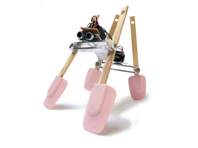 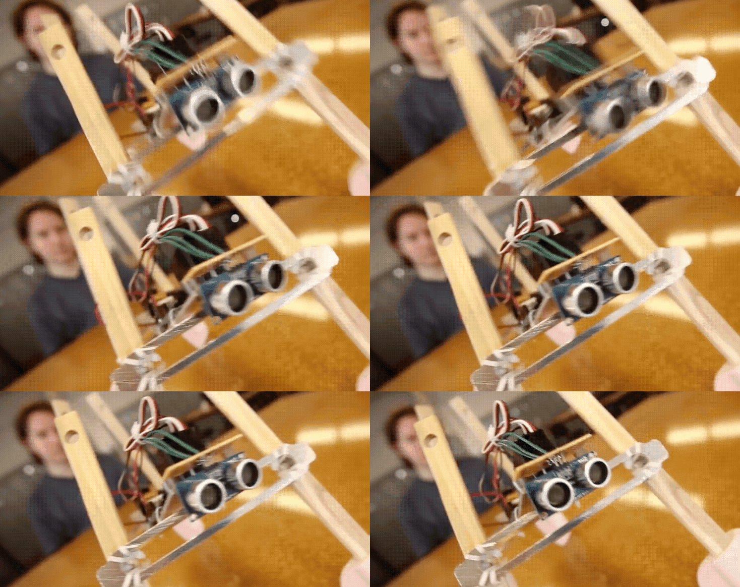 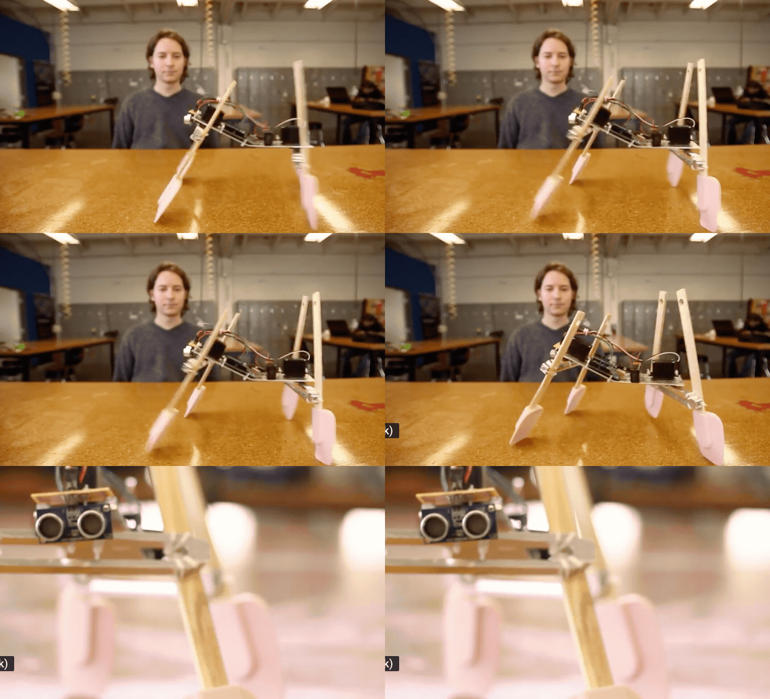 建造一个简单的步行机器人真的很容易。这个机器人基本上是由一些家用物品和一些简单的电子产品制成,你可以在Radioshack这个网站上很轻松的找到需要的电子产品。事实上,这个机器人是使用橡胶绑在一起的,这会让它的构建在进行任何的改进时非常容易。如果你对它的机构有任何的改进,只需要把橡胶皮筋解下来,然后确认好位置,再绑上就可以了,就是这么简单。 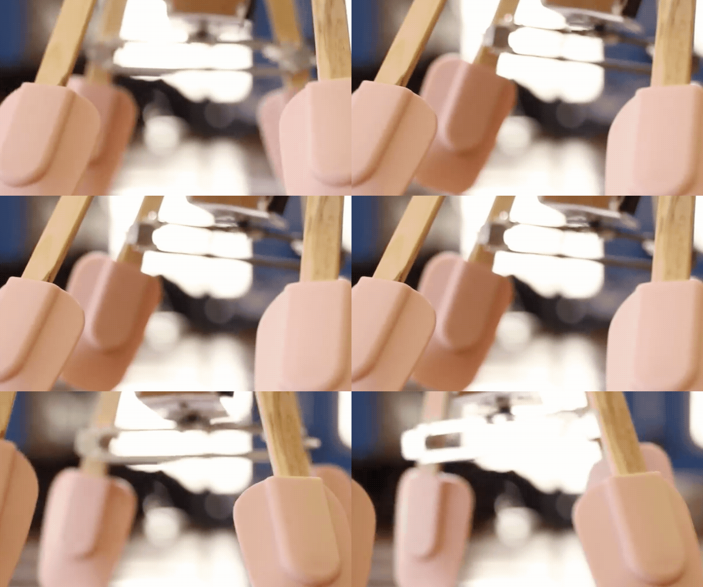 这个走路机器人的“大脑”也很容易修改,因为它是基于Arduino开发板。所以可以很方便的进行编程和更改代码,并且很简单。即使没有编程经验的人通常也可以很好的编程。 第一步:去找到需要的材料 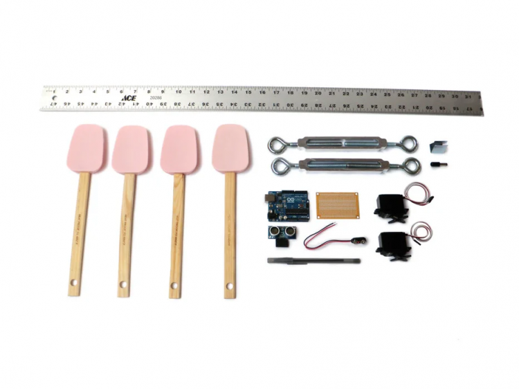 第2步:锯 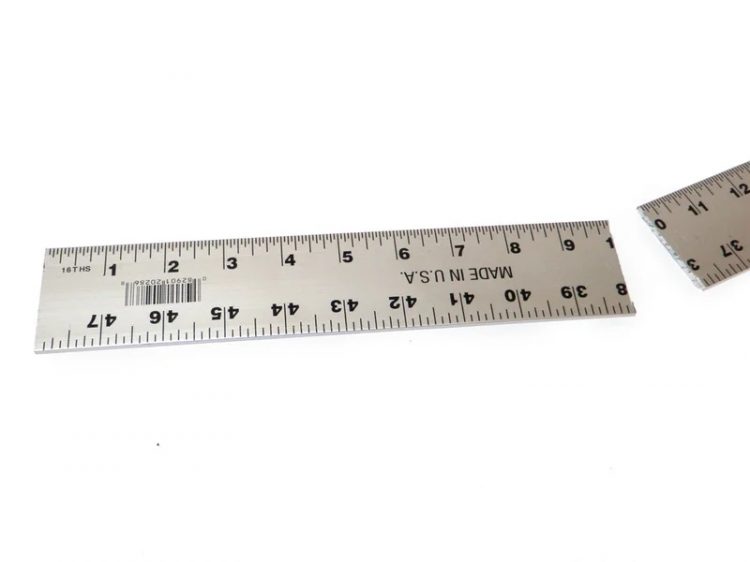 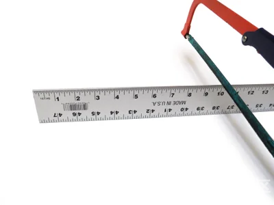  把一个20厘米的铝制尺子。 用钢锯锯成两个10厘米。 第3步:弯  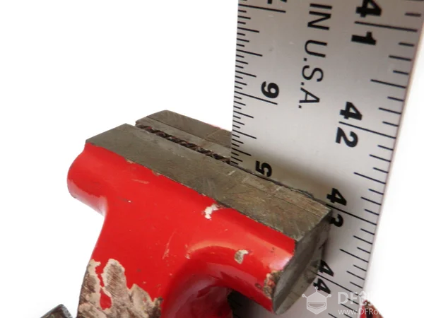 把尺子要弯曲的部分夹在台钳上,把五厘米的地方露出来。 弄弯它!!!!(约30度)。 不管你的操作过程是什么,其实到了最后的时候,只要达到的效果是一样的就行。 第4步:分开 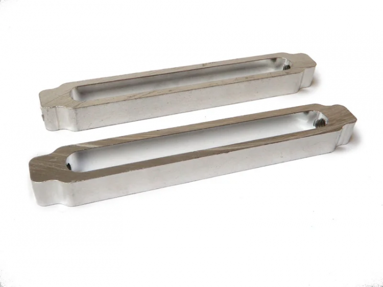 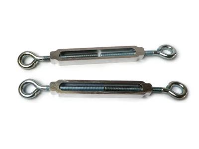 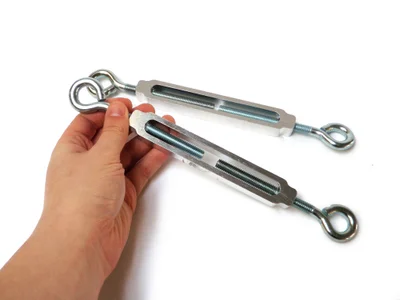  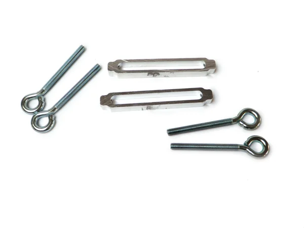 拿起你的螺丝扣,取下所有的孔眼。 将它们放在一边用于其他项目。 第5步:钻孔 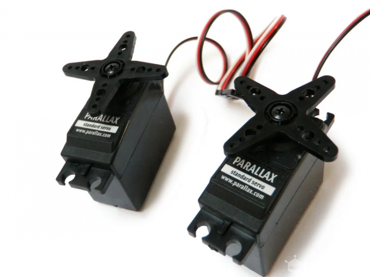   把每个伺服器的每个臂上的第二个孔加宽。 第6步:标记并钻取 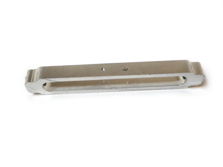 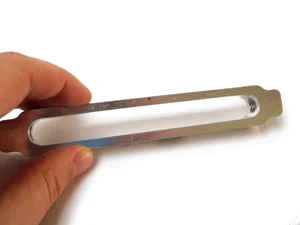 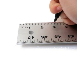 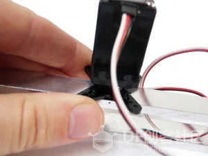  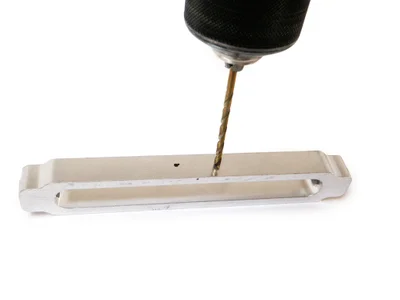 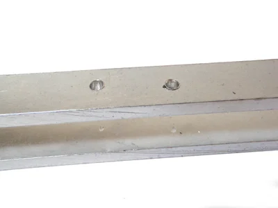 将螺丝扣放在边缘。在其中一个螺丝扣上测量3“。在此处做一个标记。在第二个螺丝扣上重复。 将伺服喇叭放在螺丝扣上的3”中心点。 将喇叭定位成使得“V”垂直于螺丝扣的长度。默认情况下,这应该定位两个指向螺丝扣每侧的“V”形状。在这些“V”形状的每个谷中做标记。 最后,用1/8“钻头钻这两个标记。 第7步:标记 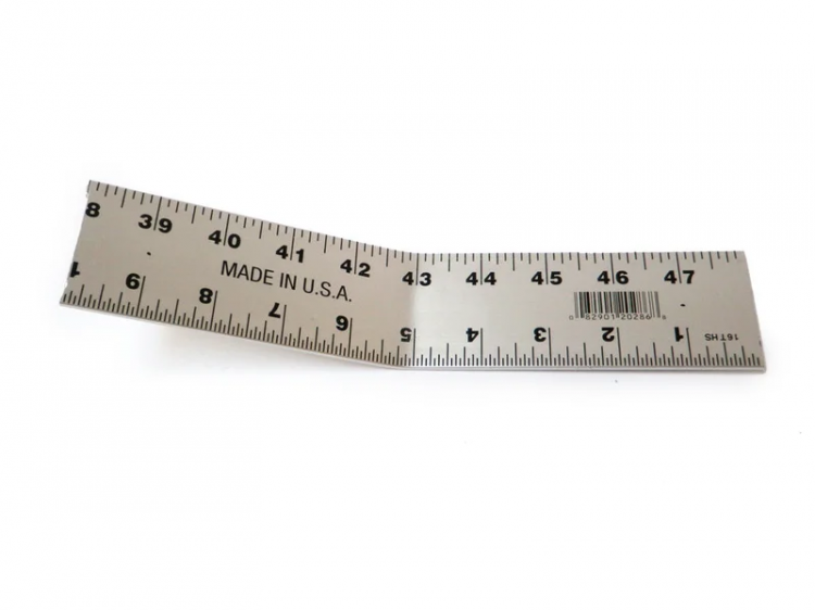 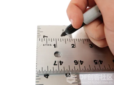  画一个居中的标记,怎么画看图吧,我有点形容不出来。 第8步:钻 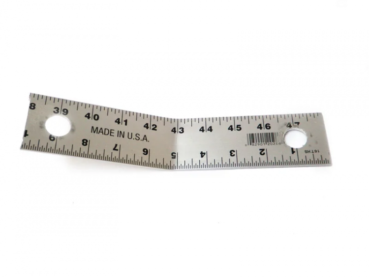 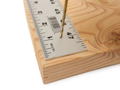  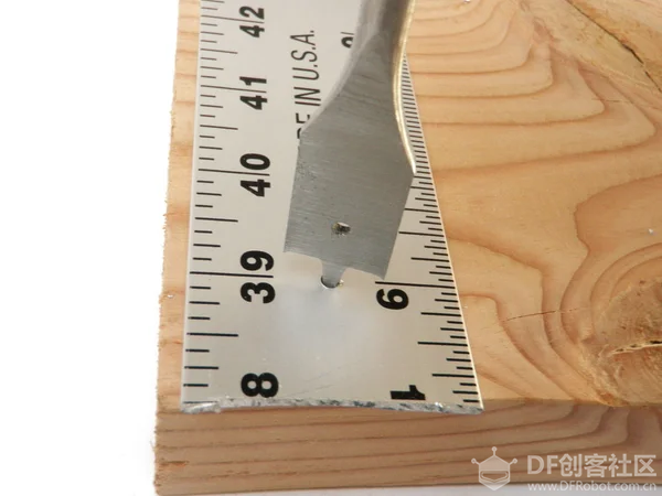 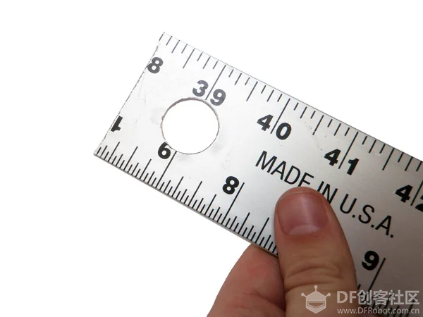 用3/4“钻头钻两个标记。 第9步:去除 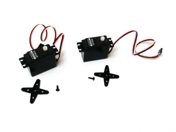  拧下固定螺钉,从伺服器上拆下伺服喇叭。 第10步:再次标记 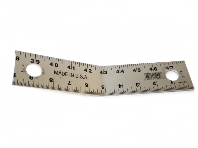 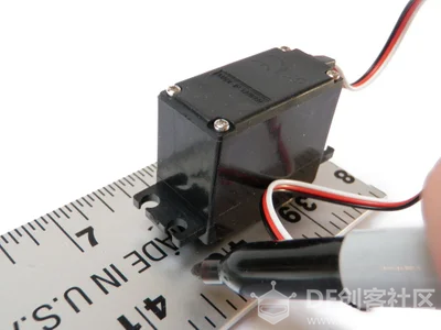 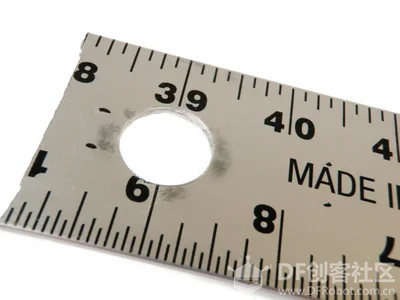 将伺服轴对准3/4“孔中的一个。使用伺服的安装孔在标尺上做4个标记。 将伺服器旋转180度,然后在另一侧重复。 第11步:继续钻孔  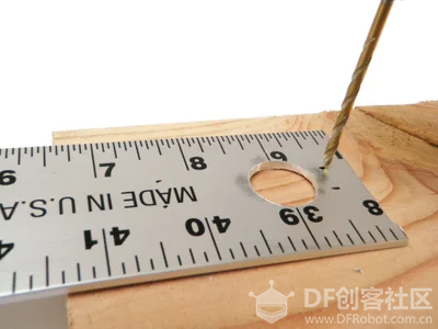 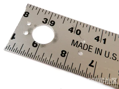 使用1/8“钻头给刚刚标记的点打孔。 第12步:安装 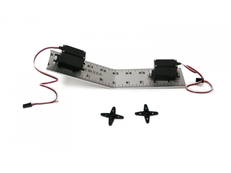 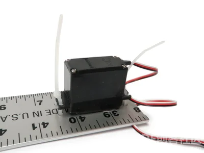 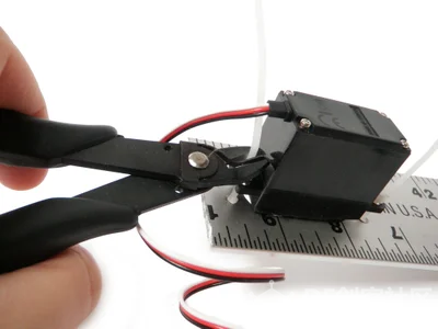 使用您刚刚钻过的安装孔将伺服器系到标尺上。 把多余的部分剪掉。 第13步:重新连接 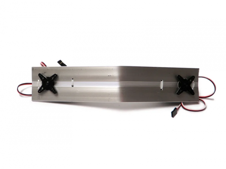 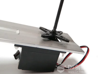 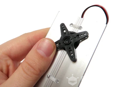 第14步:标记并钻一点  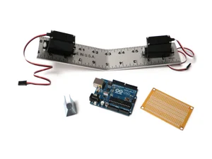 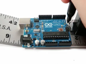 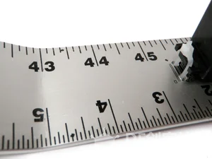  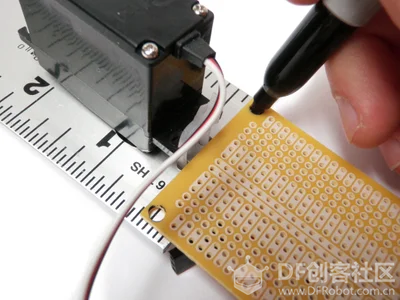 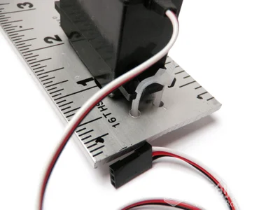 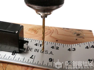  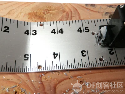 第15步:插入  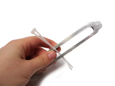 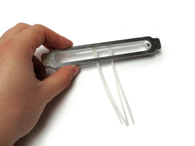 从里到外,在螺丝扣中钻出的每个孔中插入扎带。 第16步:附加 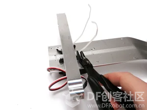 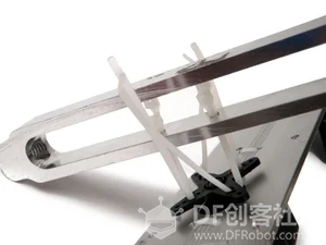 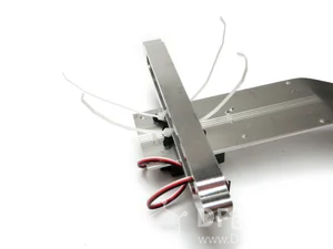 将一个螺丝扣置于伺服喇叭顶部,并垂直于标尺。扎带将螺丝扣牢固地固定到位,然后修剪掉任何多余的扎带。 第17步:安装孔  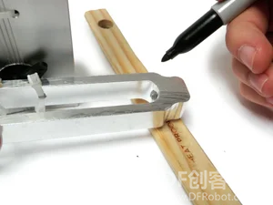  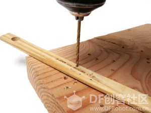 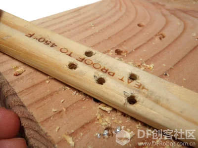 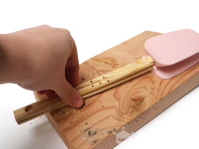 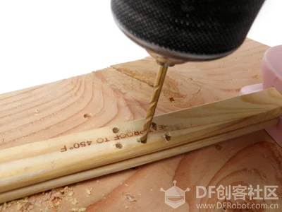 将刮刀的手柄定位在螺丝扣的大约一半处,使得这种螺丝扣垂直相交。接下来,将刮刀略微向外旋转(约10至25度)。 在螺丝扣的手柄上的螺丝刀的所有侧面上做多个标记,以指示用于拉链的钻孔到螺丝扣。 用1/8“钻头钻出你刚刚制作的标记。 将刮刀倒置,将另一把刮刀正面朝上放置。将它们对齐,使它们高度匹配。 使用第一个一组钻孔作为导向,在另一个刮刀中钻出另一组孔。这应该最终成为第一个镜像(即倒置,但在其他方面相同)。 第18步:前腿 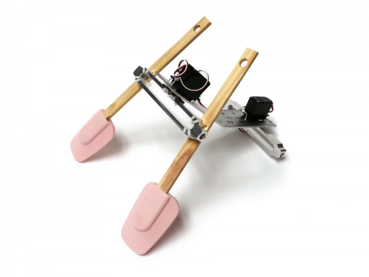 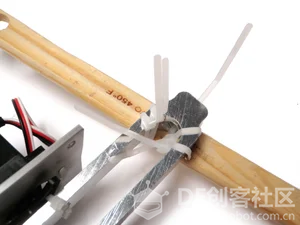 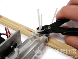 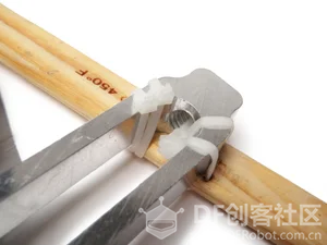 使用刚钻过的孔,将刮刀拉紧到最靠近钻孔的螺丝扣上,以便安装PCB。 为了获得最佳效果,请确保它们在位置和高度上大致相互映射。 这两把刮刀将作为前腿。 第19步:后腿 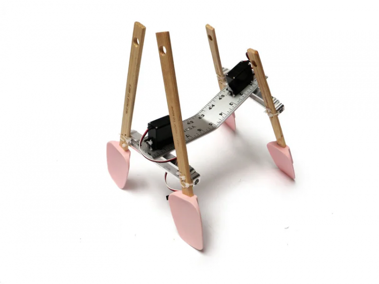 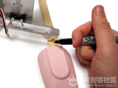 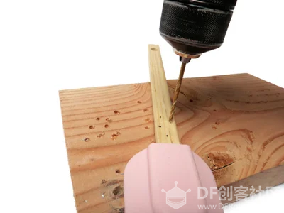 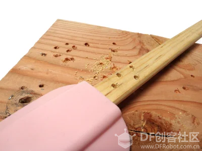 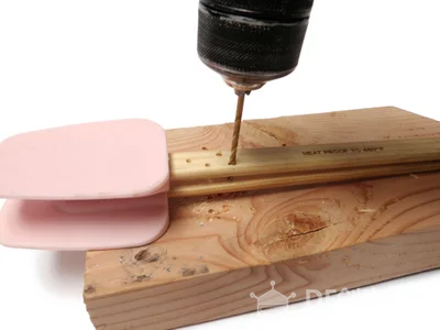 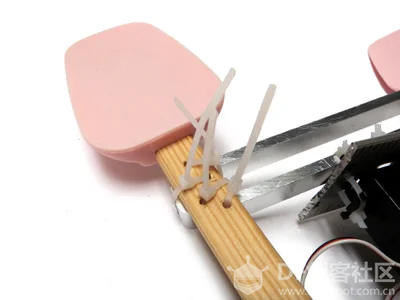  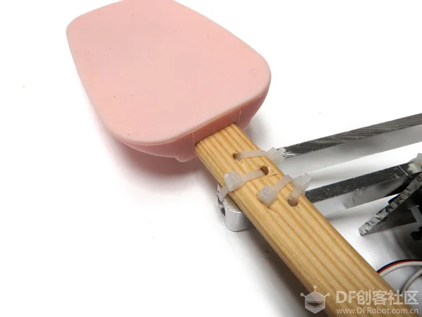 重复前腿的过程以制作后腿。 请注意,这个机器人的后腿略短于前腿。但是,这不是一个严格的规定。试验并看看哪些适合您。 第20步:间隔物   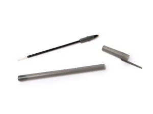 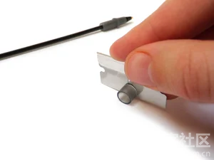 拆开圆珠笔。将笔的管子切成1/4“的部分。这些将用作安装部件的垫片 第21步:修剪   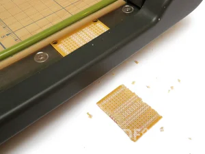 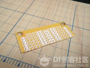 使用切纸机或剪刀,将原型板修剪至约1英寸。 步骤22:9V适配器 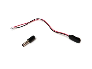 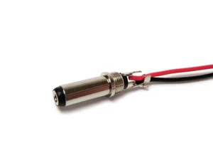 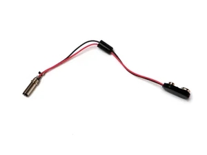 拧下M型插头并将外壳滑到9V连接器导线上,这样您以后可以将它拧回到一起(焊接后)。 将红线焊接到中央端子,将黑线焊接到插头的外部端子。 拧回插头盖。 步骤23:传感器板 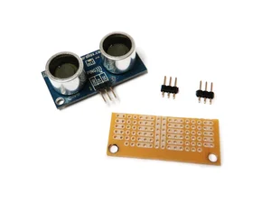 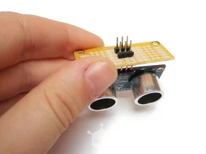 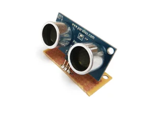 将传感器的接地导线放入沿导板长度方向移动的长导电导轨之一,并将电源导线放在另一个导线中。信号引线应位于跨越3个孔的较小导电轨之一中。 将传感器以一个小角度焊接到位,这样如果您将电路板平行于地面,它似乎会顺时针旋转约45度。 安装两个3针公头,使每一个都有一个焊接到接地轨的引脚,一个引脚焊接到电源轨上。 第24步:电线 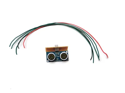 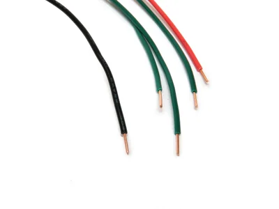 红线焊接到电源上。 黑色导线焊接地。 绿线焊接到Ping的信号引脚所连接的端子上。 绿线焊接到未连接到电源或接地连接的剩余插头引脚。 第25步:编程 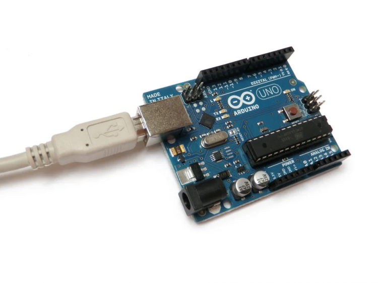 [mw_shl_code=applescript,true] /* Simple Walker Robot by Randy Sarafan This code is for controlling a simple quadruped robot and having it respond to obstacles that approach. For more information visit the project page: https://www.instructables.com/id/Simple-Walker-Robot/ This code is based on both the Arduino Sweep example by BARRAGAN and the Arduino Ping example by Tome Igoe */ #include <Servo.h> Servo myservo; // create servo object to control a servo // a maximum of eight servo objects can be created Servo myservo1; // create a second servo object to control a servo int pos = 80; // variable to store the servo position for rear legs //changing this value changes the default position of the rear legs int pos1 = 70; // variable to store the servo position for front legs //changing this value changes the default position of the front legs //determines the rate at which the legs move int rate = 1000; // this constant won't change. It's the pin number // of the sensor's output: const int pingPin = 7; void setup() { myservo.attach(9); // attaches the servo on pin 9 to the servo object myservo1.attach(10); // attaches the servo on pin 10 to the servo object myservo.write(pos); // tell servo to go to position in variable 'pos' - sets center axis myservo1.write(pos1); // tell servo to go to position in variable 'pos' - sets center axis delay(5000); } void loop() { long duration, inches, cm; // The PING))) is triggered by a HIGH pulse of 2 or more microseconds. // Give a short LOW pulse beforehand to ensure a clean HIGH pulse: pinMode(pingPin, OUTPUT); digitalWrite(pingPin, LOW); delayMicroseconds(2); digitalWrite(pingPin, HIGH); delayMicroseconds(5); digitalWrite(pingPin, LOW); // The same pin is used to read the signal from the PING))): a HIGH // pulse whose duration is the time (in microseconds) from the sending // of the ping to the reception of its echo off of an object. pinMode(pingPin, INPUT); duration = pulseIn(pingPin, HIGH); // convert the time into a distance inches = microsecondsToInches(duration); //if something is closer than a foot, back away if(inches <= 12){ backward(); } //if nothing is closer than a foot, go forwards if(inches > 12){ forward(); } } //function for going forwards void forward(){ myservo.write(pos + 20); // tell servo to go to position in variable 'pos' myservo1.write(pos1 - 20); // tell servo to go to position in variable 'pos' delay(rate); myservo.write(pos - 20); // tell servo to go to position in variable 'pos' myservo1.write(pos1 + 20); // tell servo to go to position in variable 'pos' delay(rate); } //function for backing away void backward(){ myservo.write(pos + 25); // tell servo to go to position in variable 'pos' myservo1.write(pos1 + 50); // tell servo to go to position in variable 'pos' delay(rate); myservo.write(pos - 25); // tell servo to go to position in variable 'pos' myservo1.write(pos1 - 30); // tell servo to go to position in variable 'pos' delay(rate); } long microsecondsToInches(long microseconds) { // According to Parallax's datasheet for the PING))), there are // 73.746 microseconds per inch (i.e. sound travels at 1130 feet per // second). This gives the distance travelled by the ping, outbound // and return, so we divide by 2 to get the distance of the obstacle. // See: http://www.parallax.com/dl/docs/prod/acc/28015-PING-v1.3.pdf return microseconds / 74 / 2; }[/mw_shl_code] 第26步:传感器 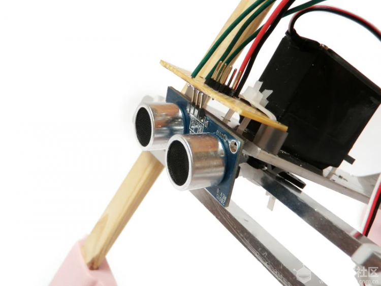 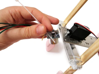 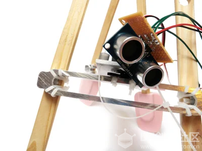 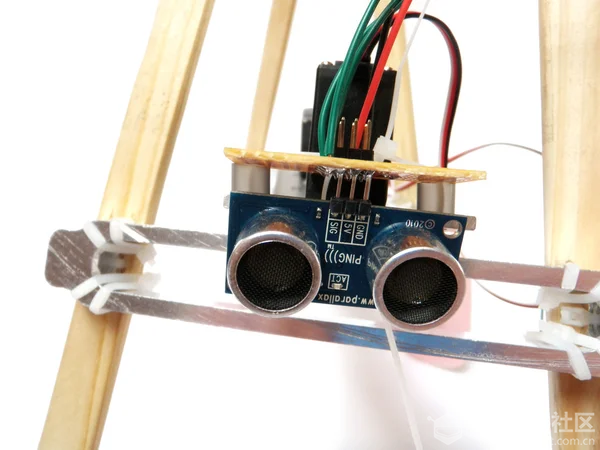 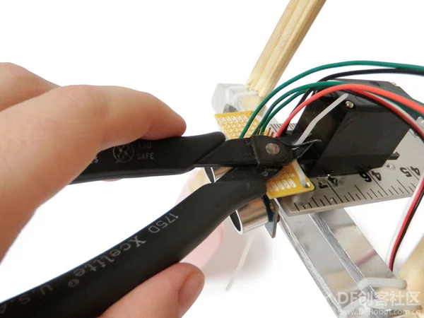 在每个PCB安装孔和PCB之间放置一个垫片。 用扎带绑牢。如果传感器没有与地面保持水平,请轻轻弯曲。 第27步:Arduino 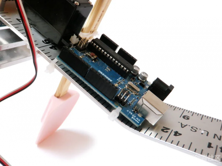 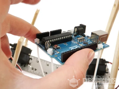 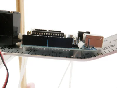 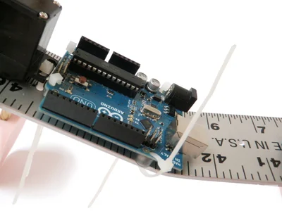 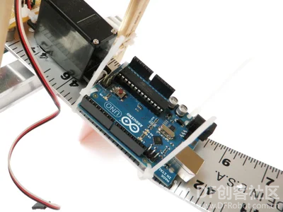  在Arduino和标尺上的每个安装孔之间放置一个垫片。也用扎带绑好。 第28步:附加 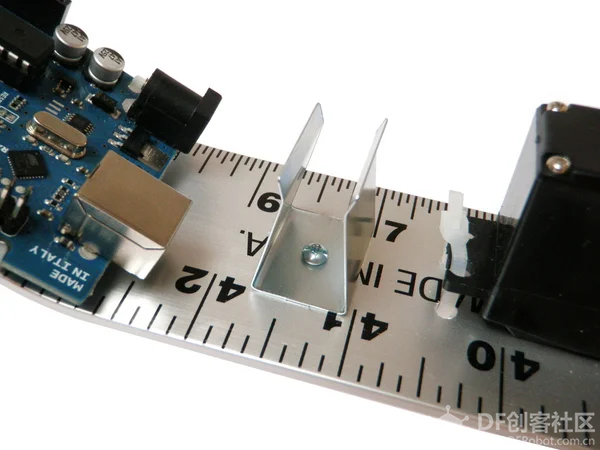 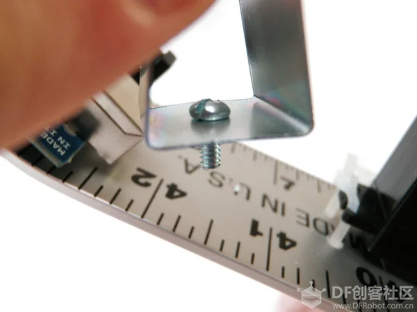 使用4-40螺母和螺栓将9V电池座固定到其安装孔中。 第29步:插头 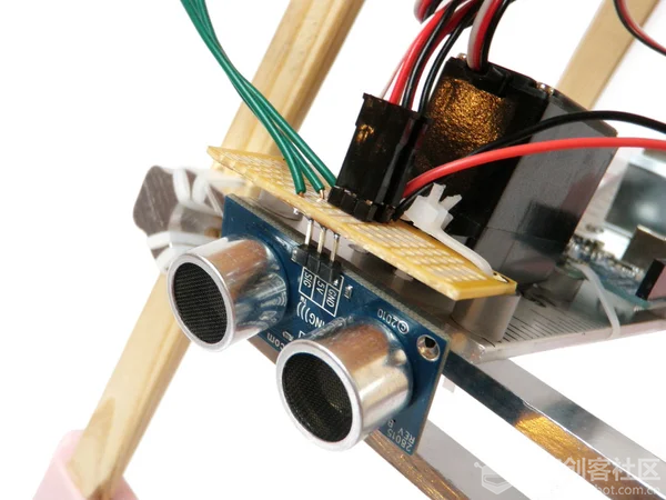 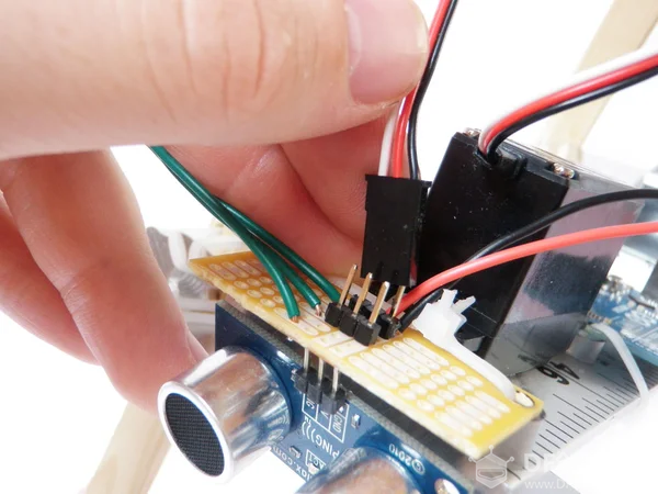 将伺服母插座插入PCB上的公头插头,确保黑色与地面对齐,红色与电源对齐,白色与绿色信号线对齐。 第30步:连线 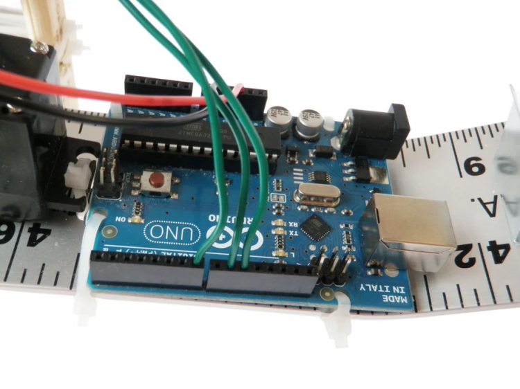 将红线从PCB插入Arduino 5V插座。 将黑色线从PCB插入Arduino接地插座。 将Ping传感器的绿线插入数字引脚插座7. 将绿色线从前伺服插入数字引脚插座9. 将后部伺服的绿线插入数字引脚10的插座。 第31步:电源 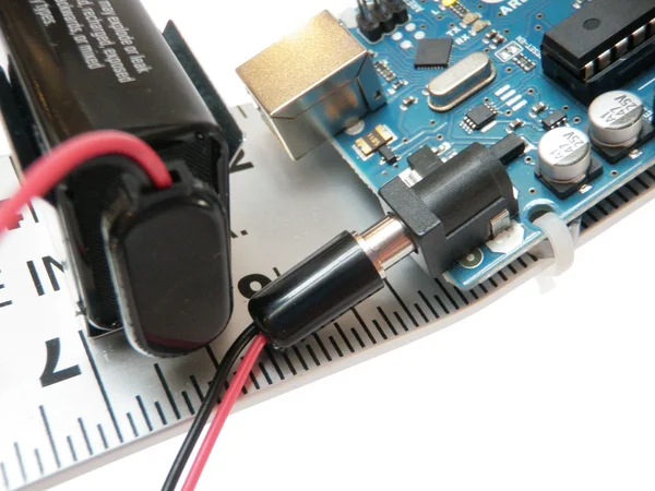 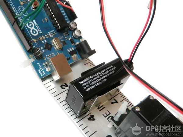 将电池连接到Arduino,将其固定在电池座中,这样就可以了。 |
 沪公网安备31011502402448
© 2013-2026 Comsenz Inc. Powered by Discuz! X3.4 Licensed