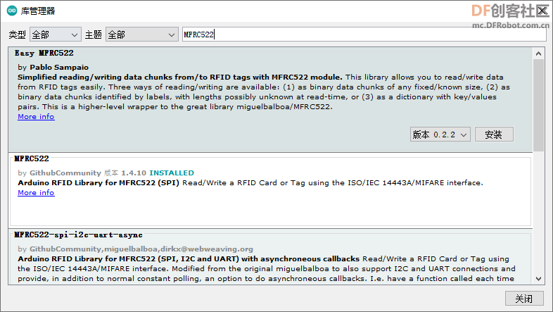
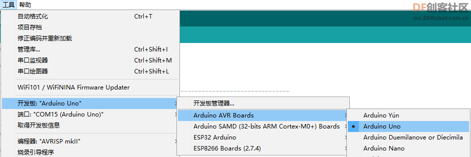
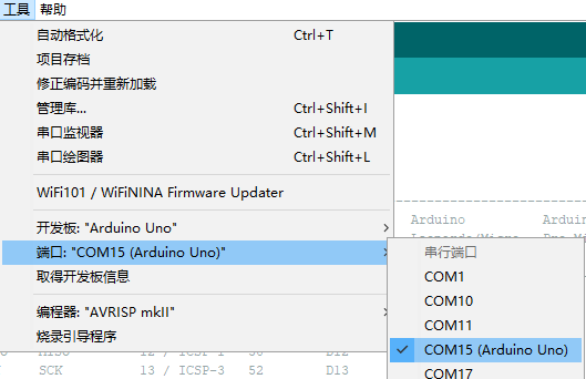
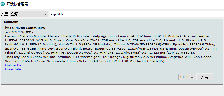
然后点击 工具-开发板-ESP8266 在目录中选择对应的型号。这样开发板就切换完成了。这个示例使用的代码如下:
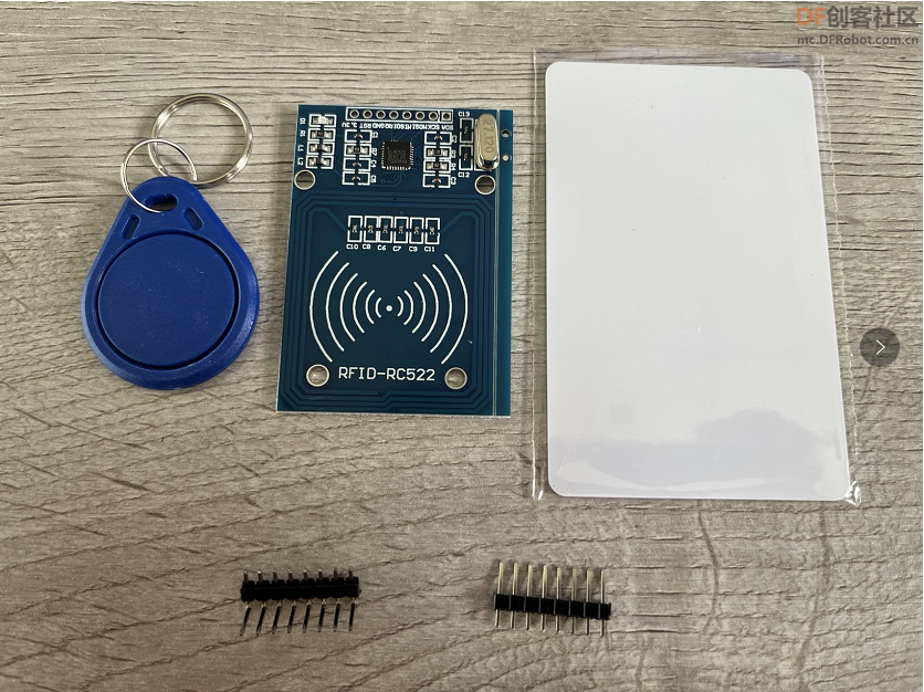
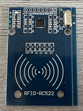
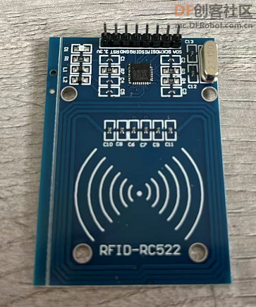
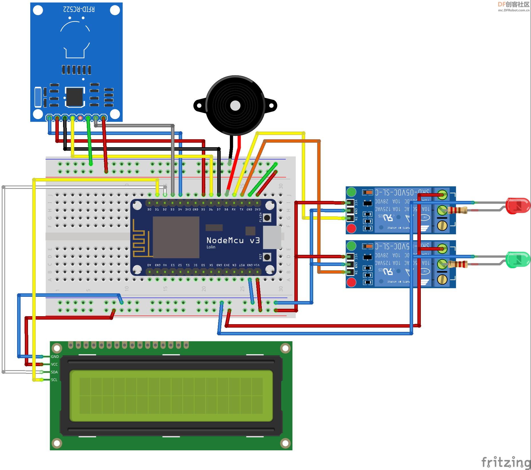
//购买之 RFID-522 脚位顺序
//RFID脚位 NodeMCU脚位
//MISO GPIO12 D6
//SCK GPIO14 D5
//SS(SDA) GPIO4 D2 有的会连 D8 配合 LCD 使用改为 D4
//MOSI GPIO13 D7
//GND
//3.3V
//RST GPIO5 D1 配合 LCD 使用改为 D3
//接无源蜂鸣器,负极接地,信号接 D8 控制输出 3V 或 0V 控制生成长短哔声
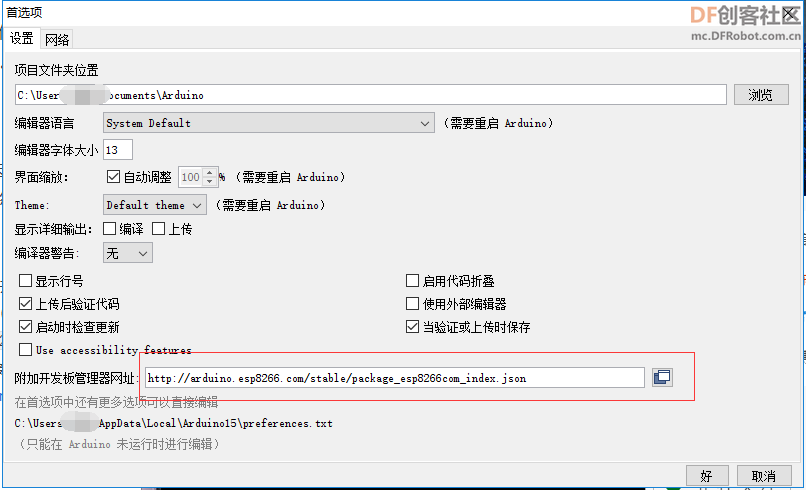
//NodeMCU 开发板偏好设置如下
// http://arduino.esp8266.com/stable/package_esp8266com_index.json
//
//LCD脚位接法 NodeMCU
//GND GND
//VSS Vin/5V
//SCL D1
//SDA D2
//蜂鸣器发出声音
//需要pitches文件
//https://gitee.com/isoface-iot/Smart/blob/master/demo/iot/s-eq-dem-2209_rfid_mqtt_relay/esp8266_ino/pitches.h
#include "pitches.h"
//创建要发音的音色数组
int Music[25] = {
NOTE_C4, NOTE_CS4, NOTE_D4, NOTE_DS4, NOTE_E4, NOTE_F4,
NOTE_FS4, NOTE_G4, NOTE_GS4, NOTE_A4, NOTE_AS4, NOTE_B4,
NOTE_C5, NOTE_CS5, NOTE_D5, NOTE_DS5, NOTE_E5, NOTE_F5,
NOTE_FS5, NOTE_G5, NOTE_GS5, NOTE_A5, NOTE_AS5, NOTE_B5
};
#include <stdio.h>
#include <stdlib.h>
#include <Arduino.h>
// WiFi 声明 ============================================================================================================================
//https://github.com/prampec/IotWebConf/tree/v2.x.x
#include <IotWebConf.h>
const char thingName[] = "Relay"; // 开发板当 AP 使用时,所采用的名称,类似 SSID.
const char wifiInitialApPassword[] = "66666666"; // 开发板当 AP 使用时,连接所需之密码.
// 在运行时使用浏览器修改设置,用户名称为 admin,密码就是上行设置值
#define STRING_LEN 128
#define NUMBER_LEN 32
#define CONFIG_VERSION "Relay01" // 配置特定密钥。如果更改了配置结构,就需修改该值.
// CONFIG_PIN 重新设置脚位,例如设 D0 脚位,在开发板启动时 与GND 脚位连接,将会重新进行,(用于密码遗忘)
#define CONFIG_PIN D0
// 状态指示器针脚,首先它会亮起(保持低电平),在Wifi连接上它会闪铄,当连接到Wifi时,它将关闭(保持高电平)。
#define STATUS_PIN LED_BUILTIN
// MQTT 声明 ============================================================================================================================
// pubsubclient MQTT 程序库网址 https://github.com/knolleary/pubsubclient
#include <PubSubClient.h>
WiFiClient espClient;
PubSubClient client(espClient);
long lastMsg = 0;
char msg[50];
int value = 0;
char hexStr[NUMBER_LEN]; // 设置 RFID 卡号
char mapic[STRING_LEN]; // 设置该机 MQTT主题名称
bool wifiready = false;
// 声明回传的方法
void configSaved();
boolean formValidator();
boolean connectAp(const char* apName, const char* password);
void connectWifi(const char* ssid, const char* password);
void charToStringL(const char S[], String &D); //将 char[] 转为 String 自订函数
DNSServer dnsServer;
WebServer server(80);
HTTPUpdateServer httpUpdater;
char mqttServerValue[STRING_LEN];
char mqttUserNameValue[STRING_LEN];
char mqttUserPasswordValue[STRING_LEN];
char mqttTopicValue[STRING_LEN];
char ipAddressValue[STRING_LEN];
char gatewayValue[STRING_LEN];
char netmaskValue[STRING_LEN];
IotWebConf iotWebConf(thingName, &dnsServer, &server, wifiInitialApPassword, CONFIG_VERSION);
IotWebConfParameter ipAddressParam = IotWebConfParameter("IP位址", "ipAddress", ipAddressValue, STRING_LEN, "text", NULL, "192.168.3.124");
IotWebConfParameter gatewayParam = IotWebConfParameter("网关", "gateway", gatewayValue, STRING_LEN, "text", NULL, "192.168.3.1");
IotWebConfParameter netmaskParam = IotWebConfParameter("子网掩码", "netmask", netmaskValue, STRING_LEN, "text", NULL, "255.255.255.0");
IotWebConfParameter mqttServerParam = IotWebConfParameter("MQTT 服务器-", "mqttServer", mqttServerValue, STRING_LEN);
IotWebConfParameter mqttUserNameParam = IotWebConfParameter("MQTT 用户", "mqttUser", mqttUserNameValue, STRING_LEN);
IotWebConfParameter mqttUserPasswordParam = IotWebConfParameter("MQTT 密码", "mqttPass", mqttUserPasswordValue, STRING_LEN, "password");
IotWebConfParameter mqttTopicParam = IotWebConfParameter("MQTT 主题", "mqttTopic", mqttTopicValue, STRING_LEN);
// 开发板固定 发送的主题 mqttTopicValue/uid 这是RFID卡号
// 开发板固定 接收的主题 mqttTopicValue/inp 自行决定发送之消息 例如 单号 货号 产品名称 可以是中文 (LCD无法显示中文)
// 开发板固定 接收的主题 mqttTopicValue/re01 =1 开启 1 号继电器 =0 关闭 1 号继电器
// 开发板固定 接收的主题 mqttTopicValue/re02 =1 开启 2 号继电器 =0 关闭 2 号继电器
IPAddress ipAddress;
IPAddress gateway;
IPAddress netmask;
// LCD1602 声明 =============================================================================================================================
//https://github.com/fdebrabander/Arduino-LiquidCrystal-I2C-library
#include <Wire.h>
#include <LiquidCrystal_I2C.h> //引用I2C库
LiquidCrystal_I2C lcd(0x27, 16, 2); //设备位址,这里的位址是0x3F,一般是0x20,或者0x27,具体看模块手册
// RFID 读卡机 声明 ===========================================================================================================================
#include <SPI.h>
#include "MFRC522.h"
#define RST_PIN D3 // RFID 读卡机的重置脚位 RC522
#define SS_PIN D4 //RFID 读卡机的芯片选择脚位
MFRC522 mfrc522(SS_PIN, RST_PIN); // 创建MFRC522物件
//============================================================================================================================================
void setup() {
Serial.begin(115200);
Serial.println();
Serial.println("Starting up...");
SPI.begin(); // Init SPI bus
mfrc522.PCD_Init(); // Init MFRC522
Serial.println("RFID ready");
// WiFi 设置 =============================================================================================================================
iotWebConf.setStatusPin(STATUS_PIN);
iotWebConf.setConfigPin(CONFIG_PIN);
iotWebConf.addParameter(&ipAddressParam);
iotWebConf.addParameter(&gatewayParam);
iotWebConf.addParameter(&netmaskParam);
iotWebConf.addParameter(&mqttServerParam);
iotWebConf.addParameter(&mqttUserNameParam);
iotWebConf.addParameter(&mqttUserPasswordParam);
iotWebConf.addParameter(&mqttTopicParam);
iotWebConf.setConfigSavedCallback(&configSaved); // 回传副程序 - 保存设置
iotWebConf.setFormValidator(&formValidator); // 回传副程序 - 检查输入参数是否有错
iotWebConf.setApConnectionHandler(&connectAp); //启动系统缺省 192.168.4.1 之AP 造成无法引入设置之IP
iotWebConf.setWifiConnectionHandler(&connectWifi); // 回传副程序 - 启动 WiFi 副程序名称 connectWifi
// -- Initializing the configuration.
boolean validConfig = iotWebConf.init();
if (!validConfig) {
mqttServerValue[0] = '\0';
mqttUserNameValue[0] = '\0';
mqttUserPasswordValue[0] = '\0';
}
else
{
strcpy(mapic, mqttTopicValue);
}
// -- 在Web服务器上设置必需的URL处理进程.
server.on("/", handleRoot);
server.on("/config", [] { iotWebConf.handleConfig(); });
server.onNotFound([]() {
iotWebConf.handleNotFound();
});
//设置 MQTT ===================================================================================================
// client.setServer("192.168.3.125", 1883);
client.setServer(mqttServerValue, 1883);
client.setCallback(callback);
if (client.connected()) {
char mymapic[STRING_LEN];
strcpy(mymapic, mapic); // strcpy(复制目的字符串,来源字符串
strcat(mymapic, "/#");
client.subscribe(mymapic);
}
//设置蜂鸣器===================================================================================================
pinMode(D8, OUTPUT); //设置 D8 脚位用于控制蜂鸣
lcd.begin(); // 初始化LCD
lcd.backlight(); //设置LCD背景等亮
//设置继电器===================================================================================================
pinMode(D9, OUTPUT); //设置继电器使用 D9 D10 脚位为输出状态
pinMode(D10, OUTPUT);
digitalWrite(D9,HIGH);
digitalWrite(D10,HIGH);
}
void loop() {
// WiFI 运行 ============================================================================================================================
iotWebConf.doLoop(); // -- 尽可能频繁地调用doLoop.
// MQTT 接收主题(单号) ========================================================================================================================
client.loop();
if (client.connected()) {
// RFID 运行 ============================================================================================================================
if ( ! mfrc522.PICC_IsNewCardPresent()) { // 检查是否为新卡
delay(50);
return;
}
// Select one of the cards
if ( ! mfrc522.PICC_ReadCardSerial()) {
delay(50);
return;
}
else
{
// Show some details of the PICC (that is: the tag/card)
Serial.print(F("Card UID:"));
// 转换卡号以十六进位的字符串显示
to_hex(mfrc522.uid.uidByte, mfrc522.uid.size);
// 蜂鸣器响声
beep(23); //不可大于 24
//发送卡号到 MQTT Broker
char pubmapic[STRING_LEN];
strcpy (pubmapic, mapic);
strcat(pubmapic, "/uid");
Serial.println(pubmapic);
// MQTT 发送主题(卡号) ========================================================================================================================
Serial.println("connected");
Serial.println(pubmapic);
client.publish(pubmapic, hexStr);
delay(1500); //得暂停 要不然回圈会很快扫卡 读好几次
}
}
else
{
if (wifiready) {
reconnect();
}
}
/** 此段程序取消 因为会紧跟着显示 hello Word 信号数
将来在发送大量字符串时可以参考使用
long now = millis();
if (now - lastMsg > 2000) {
lastMsg = now;
++value;
snprintf (msg, 50, "hello world #%ld", value);
Serial.print("Publish message: ");
Serial.println(msg);
client.publish("outTopic", msg);
}
**/
}
// RFID 副程序 =============================================================================================================================
void beep(int len) {
for (int i = 0; i < len; i++) {
tone(D8, Music[i], 100); // 从第8Pin发声,发出100ms的声音
//delay(200);
}
}
// -----------------------------------------------------------------------------------------------------------------------------------------------
// 转换卡号以十六进位的字符串显示
void to_hex(byte *buffer, byte buffSize) {
char* s = &hexStr[0];
for (byte i = 0; i < buffSize; i++) {
snprintf(s, 3, "%02x", buffer[i]);
s += 2;
}
hexStr[buffSize * 2] = 0;
Serial.println(hexStr);
lcd.clear(); //显示清除
lcd.setCursor(0, 0); //设置显示行列数
lcd.print(F("Card UID:")); //输出字符到LCD1602上
lcd.setCursor(0, 1);
lcd.print(hexStr);
}
// WiFi 副程序 =============================================================================================================================
void handleRoot() //处理“/”路径的Web请求.
{
// -- 让IotWebConf测试并处理强制门户请求.
if (iotWebConf.handleCaptivePortal())
{
// -- 主要的需 求已经提供.
return;
}
String s = "<!DOCTYPE html><html lang=\"en\"><head><meta name=\"viewport\" charset=\"utf-8\" content=\"width=device-width, initial-scale=1, user-scalable=no\"/>";
s += "<title>网络设置作业</title></head><body>您好!";
s += "<ul>";
s += "<li>固定 IP 设置: ";
s += ipAddressValue;
s += "</ul>";
s += "请至<a href='config'>设置页面</a> 请修改.";
s += "</body></html>\n";
server.send(200, "text/html", s);
}
// -----------------------------------------------------------------------------------------------------------------------------------------------
void configSaved()
{
Serial.println("设置即将更新.");
}
// -----------------------------------------------------------------------------------------------------------------------------------------------
boolean formValidator()
{
Serial.println("Validating form.");
boolean valid = true;
if (!ipAddress.fromString(server.arg(ipAddressParam.getId())))
{
ipAddressParam.errorMessage = "请提供正确的 IP 位址!";
valid = false;
}
if (!netmask.fromString(server.arg(netmaskParam.getId())))
{
netmaskParam.errorMessage = "请提供正确的子网掩码!";
valid = false;
}
if (!gateway.fromString(server.arg(gatewayParam.getId())))
{
gatewayParam.errorMessage = "请提供正确的网关位址!";
valid = false;
}
return valid;
}
// -----------------------------------------------------------------------------------------------------------------------------------------------
boolean connectAp(const char* apName, const char* password)
{
// -- 自定义AP设置
return WiFi.softAP(apName, password, 4);
}
// -----------------------------------------------------------------------------------------------------------------------------------------------
void connectWifi(const char* ssid, const char* password)
{
ipAddress.fromString(String(ipAddressValue));
netmask.fromString(String(netmaskValue));
gateway.fromString(String(gatewayValue));
if (!WiFi.config(ipAddress, gateway, netmask)) {
Serial.println("WiFi 连接失败 请检查网络设置");
}
wifiready = true;
Serial.print("ip: ");
Serial.println(ipAddress);
Serial.print("gw: ");
Serial.println(gateway);
Serial.print("net: ");
Serial.println(netmask);
WiFi.begin(ssid, password);
}
// MQTT 副程序 =============================================================================================================================
// 接收主题後调用进程
void callback(char* topic, byte* payload, unsigned int length) {
String mapre01; // 预定收到的主题1 /re01
String mapre02; // 预定收到的主题2 /re02
String mapre03; // 预定收到的主题3 /inp
String mappu01; // 预定发送的主题3 /UID
String mapres; // 实际从 MQTT Broker 接收到的主题
String information; // 实际从 MQTT Broker 接收到的主题内容
String RelayOpen="1";
//将 char[] 转为 String charToStringL(需转换的 Char数组, 转换後的 String)
charToStringL(mapic, mapre01); //用户自设的主题
charToStringL(mapic, mapre02);
charToStringL(mapic, mapre03);
charToStringL(mapic, mappu01);
mapre01 = mapre01 + "/re01"; //1号继电器 的主题
mapre02 = mapre02 + "/re02"; //2号继电器 的主题息
mapre03 = mapre03 + "/inp"; //其他收到的主题
mappu01 = mappu01 + "/uid"; //发布的主题
charToStringL(topic, mapres); //实际从 MQTT Broker 接收到的主题
for (int i = 0; i < length; i++) { //读取收到的字符串
information = information + (char)payload[i];
}
if (mapres != mappu01) { // 不显示发布的主题
Serial.print("接收消息 " + mapres + " [");
Serial.print(information);
Serial.print("] ");
lcd.clear(); // LCD 显示清除
lcd.setCursor(0, 0); // 设置显示行列数
lcd.print("Message:");
lcd.setCursor(0, 1);
beep(15); // 蜂鸣器响声 24
beep(15);
}
if (mapres == mapre01) {
if (information == RelayOpen) {
Serial.println("Open Relay-1");
lcd.print("Open Relay-1"); //输出消息到 LCD1602 显示
digitalWrite(D9,LOW);
}
else {
Serial.println("Close Relay-1");
lcd.print("Close Relay-1");
digitalWrite(D9,HIGH);
}
}
if (mapres == mapre02) {
if (information == RelayOpen) {
Serial.println("Open Relay-2");
lcd.print("Open Relay-2");
digitalWrite(D10,LOW);
}
else {
Serial.println("Close Relay-2");
lcd.print("Close Relay-2");
digitalWrite(D10,HIGH);
}
}
if (mapres == mapre03) {
lcd.print(information);
}
/**
digitalWrite(D9,LOW);
delay(200);
digitalWrite(D10,LOW);
delay(2000);
digitalWrite(D9,HIGH);
delay(200);
digitalWrite(D10,HIGH);
delay(1000);
**/
Serial.println();
// 收到消息的第一个字符 开发板上 LED 亮灯
if ((char)payload[0] == '1') {
digitalWrite(BUILTIN_LED, LOW); // Turn the LED on (Note that LOW is the voltage level
// but actually the LED is on; this is because
// it is active low on the ESP-01)
} else {
digitalWrite(BUILTIN_LED, HIGH); // 关闭 LED 灯
}
}
void reconnect() {
// 一直循环直到连上 MQTT Broker
while (!client.connected()) {
Serial.print("正在连接 MQTT Broker...");
// 随机生成 client ID
String clientId = "ESP8266Client-";
clientId += String(random(0xffff), HEX);
// 开始进行连接
lcd.clear(); // LCD 显示清除
lcd.setCursor(0, 0); // 设置显示行列数
if (client.connect(clientId.c_str(), mqttUserNameValue, mqttUserPasswordValue)) {
Serial.println("MQTT Broker 已经连接上");
char mymapic[STRING_LEN];
strcpy(mymapic, mapic); // strcpy(复制目的字符串,来源字符串
strcat(mymapic, "/#");
client.subscribe(mymapic);
lcd.print("RFID Ready:"); // 正确开机 在LCD 显示消息
} else {
Serial.print("连接失败, rc=");
Serial.print(client.state());
Serial.println("五秒钟之后再连接");
lcd.print("failed, rc="); // 在LCD 显示错误消息
lcd.print(client.state());
lcd.setCursor(0, 1);
lcd.print("try again in 5 seconds... ");
delay(5000);
}
}
}
//将 char[] 转为 String 自订函数
void charToStringL(const char S[], String & D)
{
byte at = 0;
const char *p = S;
D = "";
while (*p++) {
D.concat(S[at++]);
}
}
刷写完成后,重启 ESP8266 ,此时 WiFi 是以 AP 模式运行的,我们用手机或者电脑连接到SSID为 Relay 的无限网络,使用浏览器访问 http://192.168.4.1,打开网页页面,点击设置页面,进入设置的页面程序。根据页面要求设置对应的连接项或者设置项,其中的 MQTT 相关的设置项是为后续的连接作铺垫的,所以测试时,也请先设置好可用的MQTT服务器。设置保存后断开连接,并重启ESP8266。
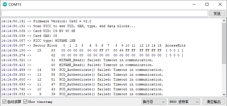
在通电后,请先立即移除 ESP8266 针脚 TX RX 的连接,查看 LCD 屏幕的显示情况。等待 LCD 屏幕显示 RFID Ready 后,再将 TX RX 针脚重新接上。这个时候,可以将卡片放置于 MFRC522 的感应区,可以听到蜂鸣器的声音,同时屏幕上会显示刷卡的结果。
到这里了,你可能会问,这个继电器怎么没用上啊?MQTT 是干什么用的?接下来还会有更新的内容,希望大家能持续关注。


 沪公网安备31011502402448
 置顶卡
置顶卡 变色卡
变色卡 千斤顶
千斤顶


