|
前一段入手了 ESP32-S3-WROOM-1-N4模组(DFR0896),拿到手之后发现包装非常有意思:类似于糖果。 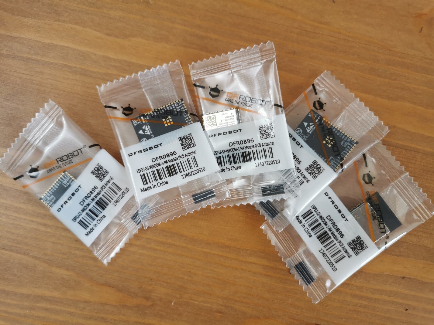
接下来就开始研究如何使用它们。经过研究电路部分和之前的 ESP32 S3非常类似,同时参考之前 ESP32 S2 的设计,绘制一个最小系统的电路图。因为这是ESP32S3 模块,工作需要的晶振已经集成在模块内部中,所以外围只需要很少的元件即可工作: 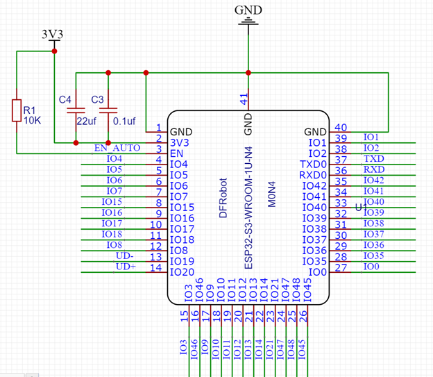
其余部分是特别预留的USB接口,以及串口下载部分和供电部分(POWER): 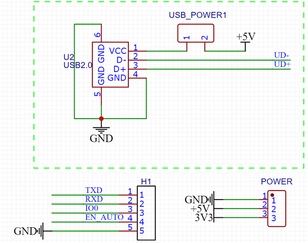
下载部分提供了 TX 和 RX, 此外 IO0和 EN_AUTO 配合能够实现自动下载。供电部分由外部引入3.3V和5V 电源,后者是专门给USB设备进行供电的。 特别注意:嘉立创库中的 ESP32 S3 模块绘制有问题,元件引脚和PAD对应错误,因此我自己修改出一个命名为 DFROBOT ESP32-S3-WROOM-1U-N4。另外,ESP32S3 和 S2 模组虽然都是邮票孔,但是引脚间距不同,在使用中如果使用 S2作为参考务必注意这一点。 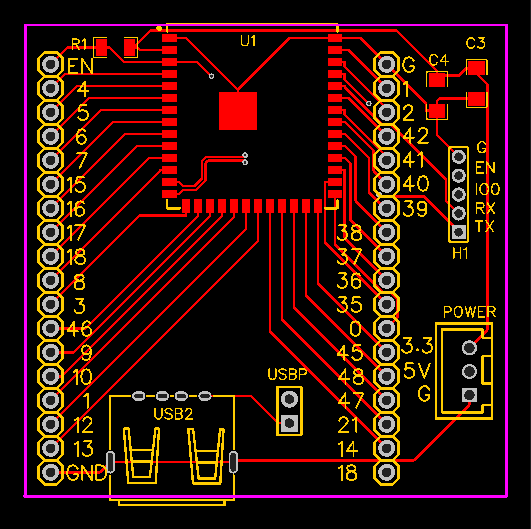
此外,上图和手册相比中间EPAD稍微有些差别,我是直接将他们放在一起的没有分开成9个方块,这个PAD更多是为了散热考虑,所以修改不会由影响。 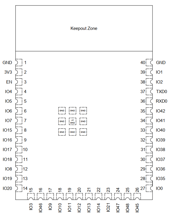
拿到手的板子是这样的: 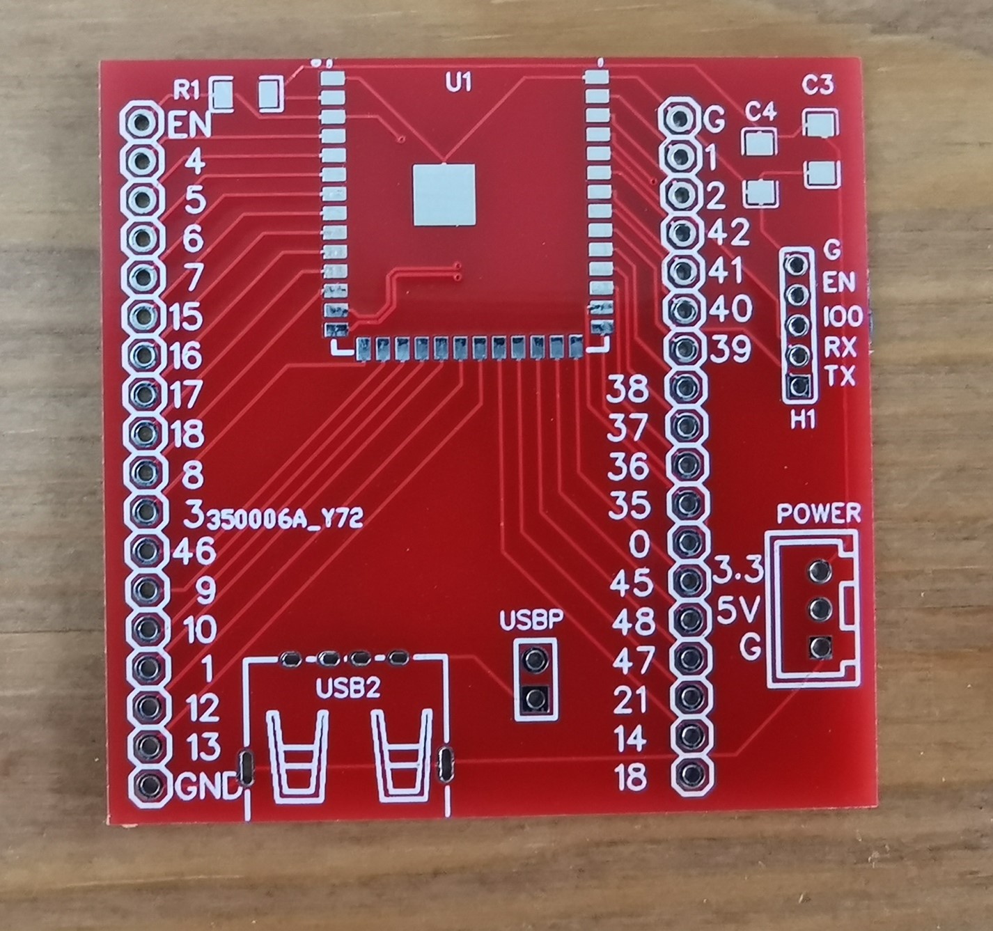
焊接之后是这样的: 
烧写代码是位于C:\Users\Username\AppData\Local\ Arduino15\packages\esp32\hardware\esp32\2.0.3\libraries\USB\examples\Keyboard\KeyboardMessage 的ESP32 示例代码:
- /*
- Keyboard Message test
-
- For the Arduino Leonardo and Micro.
-
- Sends a text string when a button is pressed.
-
- The circuit:
- - pushbutton attached from pin 0 to ground
- - 10 kilohm resistor attached from pin 0 to +5V
-
- created 24 Oct 2011
- modified 27 Mar 2012
- by Tom Igoe
- modified 11 Nov 2013
- by Scott Fitzgerald
-
- This example code is in the public domain.
-
- http://www.arduino.cc/en/Tutorial/KeyboardMessage
- */
- #if ARDUINO_USB_MODE
- #warning This sketch should be used when USB is in OTG mode
- void setup(){}
- void loop(){}
- #else
-
- #include "USB.h"
- #include "USBHIDKeyboard.h"
- USBHIDKeyboard Keyboard;
-
- const int buttonPin = 0; // input pin for pushbutton
- int previousButtonState = HIGH; // for checking the state of a pushButton
- int counter = 0; // button push counter
-
- void setup() {
- // make the pushButton pin an input:
- pinMode(buttonPin, INPUT_PULLUP);
- // initialize control over the keyboard:
- Keyboard.begin();
- USB.begin();
- }
-
- void loop() {
- // read the pushbutton:
- int buttonState = digitalRead(buttonPin);
- // if the button state has changed,
- if ((buttonState != previousButtonState)
- // and it's currently pressed:
- && (buttonState == LOW)) {
- // increment the button counter
- counter++;
- // type out a message
- Keyboard.print("You pressed the button ");
- Keyboard.print(counter);
- Keyboard.println(" times.");
- }
- // save the current button state for comparison next time:
- previousButtonState = buttonState;
- }
- #endif /* ARDUINO_USB_MODE */
特别注意还需要设置编译选项: 
之后可以看到 
有了最小系统,用户可以方便的移植到自身的设计中。
| 


 ESP32S3MINI.zip