|
8715| 1
|
[入门] StickV的串口通信与servo-hat应用 |
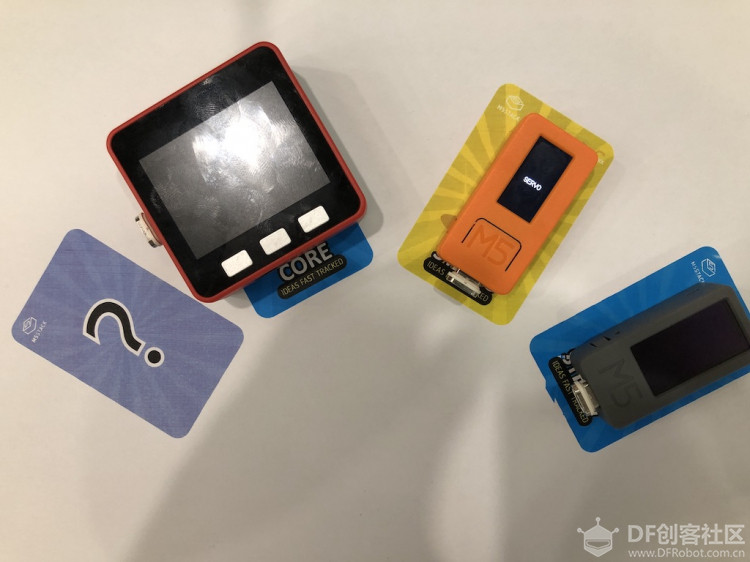
本帖最后由 vany5921 于 2019-9-27 17:07 编辑  servo-hat是一款舵机模块,通过esp32的ledc可以直接输出PWM进行控制标称输出角度为145°±10°,实测可以达到170多度。由于ledc配置比较简单因此没有封装库,使用前简单配置一下参数。 [mw_shl_code=c,true]#define COUNT_LOW 1800 #define COUNT_HIGH 8000 #define TIMER_WIDTH 16 #include "esp32-hal-ledc.h" #include <M5StickC.h> void setup() { // put your setup code here, to run once: M5.begin(); ledcSetup(1, 50, TIMER_WIDTH); ledcAttachPin(26, 1); / M5.Lcd.setCursor(20, 80, 2); M5.Lcd.print("SERVO"); } void loop() { // put your main code here, to run repeatedly: for(int i = COUNT_LOW; i < COUNT_HIGH; i = i+100){ ledcWrite(1, i); delay(50); } }[/mw_shl_code]  有了以上的基础,接下来做一个虚拟指针。最终实现效果为根据Stickv识别的物体,由舵机指向该物体。StickV有GROVE输出,可自由配置IO控制舵机,但由于servo-hat需要配合StickC,因此将StickV的GROVE配置为UART与StickC进行通信,StickC根据接收信息控制舵机。 首先需要对StickV进行模型训练操作,具体方法参考V-TRAINING https://docs.m5stack.com/#/en/related_documents/v-training  模型训练好以后修改boot.py,通过fpioa_manager配置UART,CONNEXT_A为RX,CONNEXT_B为TX [mw_shl_code=python,true]import image import lcd import sensor import sys import time import KPU as kpu from fpioa_manager import fm from machine import UART fm.register(board_info.CONNEXT_A,fm.fpioa.UART1_RX) fm.register(board_info.CONNEXT_B,fm.fpioa.UART1_TX) uart_A = UART(UART.UART1, 115200) lcd.init() lcd.rotation(2) try: img = image.Image("/sd/startup.jpg") lcd.display(img) except: lcd.draw_string(lcd.width()//2-100,lcd.height()//2-4, "Error: Cannot find start.jpg", lcd.WHITE, lcd.RED) task = kpu.load("/sd/b7fbf3aad4caf26a_mbnet10_quant.kmodel") labels=["M5Stack Fire","M5StickC","M5Stick"] #You can check the numbers here to real names. sensor.reset() sensor.set_pixformat(sensor.RGB565) sensor.set_framesize(sensor.QVGA) sensor.set_windowing((224, 224)) sensor.run(1) lcd.clear() while(True): img = sensor.snapshot() fmap = kpu.forward(task, img) plist=fmap[:] pmax=max(plist) max_index=plist.index(pmax) a = lcd.display(img) uart_A.write('clear') uart_A.write('\r') if pmax > 0.95: lcd.draw_string(5, 60, "Accu:%.2f Type:%s"%(pmax, labels[max_index].strip())) uart_A.write(labels[max_index]) uart_A.write('\r') a = kpu.deinit(task) [/mw_shl_code] 本例训练了3个模型,分别为M5Stack Fire,M5StickC,M5Stick。识别到目标后串口输出目标对象。 接下来进行StickC端的代码编写,配置ledc,对串口字符进行处理,这里对串口数据转换为字符串进行对比,根据结果控制舵机旋转指定的位置 [mw_shl_code=c,true]#include "esp32-hal-ledc.h" #include <M5StickC.h> #define TIMER_WIDTH 16 //精度 #define CHANNEL 0 //通道 #define FREQUANCE 50 //频率 #define PIN 26 //舵机引脚 String comData = ""; String lastContent = ""; bool flag; void setup() { M5.begin(); // Serial2.begin(unsigned long baud, uint32_t config, int8_t rxPin, int8_t txPin, bool invert) Serial2.begin(115200, SERIAL_8N1, 33, 32); //串口2初始化操作 ledcSetup(CHANNEL, FREQUANCE, TIMER_WIDTH); ledcAttachPin(PIN, CHANNEL); } void loop() { if(Serial2.available()){ comData = ""; while(Serial2.available()){ char ch = Serial2.read(); if(ch != '\r'){ comData += ch; } } if(comData == "clear"){ M5.Lcd.fillScreen(BLACK); comData = ""; ledcWrite(CHANNEL, 8000); return; } if(lastContent != comData){ M5.Lcd.setCursor(0, 0); M5.Lcd.print(comData); } if(comData == "M5StickC"){ ledcWrite(CHANNEL, 5000); }else if(comData == "M5Stack Fire"){ ledcWrite(CHANNEL, 6500); }else if(comData == "M5Stick") ledcWrite(CHANNEL, 8000); } } [/mw_shl_code] 视频效果如下: |
 沪公网安备31011502402448
© 2013-2026 Comsenz Inc. Powered by Discuz! X3.4 Licensed