本帖最后由 yumekikls 于 2023-12-4 09:08 编辑
在物理实验中时常需要记录周期性运动的数据,为了得到其周期,可以导入python或其他程序进行离散傅里叶分析。
不过,每次都导入其他程序分析总显得麻烦,故本帖尝试寻找一种方法,让单片机自己记录好数据后自动找到周期性运动的频率。
经测试,一般UNO或pro mini类存储空间不够,故改用Seeed Studio XIAO nRF52840 Sense
官网见:https://wiki.seeedstudio.com/XIAO_BLE/
- #include <avr/pgmspace.h>
- #include <math.h>
-
- #define N 256 // Number of samples for DFT
-
- double real[N];
- double imag[N];
-
- void setup() {
- Serial.begin(9600);
- while (!Serial) {
- ; // Wait for serial port to connect
- }
- }
-
- void loop() {
- // Read analog input from A0
- for (int i = 0; i < N; i++) {
- double val = cos(2.0 * M_PI * 8.0 * i/255.0); //生成一个频率为8Hz的信号,时间长度为1秒
- real[i] = val; // Store sample in the real array
- imag[i] = 0; // Initialize imaginary part to 0
- }
-
- // Perform DFT
- for (int k = 0; k < N; k++) {
- double sumReal = 0;
- double sumImag = 0;
-
- for (int t = 0; t < N; t++) {
- double angle = 2 * M_PI * t * k / N;
- sumReal += real[t] * cos(angle) + imag[t] * sin(angle);
- sumImag += -real[t] * sin(angle) + imag[t] * cos(angle);
- }
-
- // Normalize the result
- double magnitude = sqrt(sumReal * sumReal + sumImag * sumImag) / N;
-
- // Output the magnitude to the serial monitor
- Serial.print(k);
- Serial.print("\t");
- Serial.print(magnitude);//输出频谱纵轴
- Serial.print("\t");
- Serial.println(real[k]); //输出原始周期信号
- }
-
- delay(5000); // Delay for 5 second before the next measurement
- }
类似于示波器切片输出,单片机每256个数据后等待5秒,方便复制序列窗口的内容到Excel测试。结果如下:
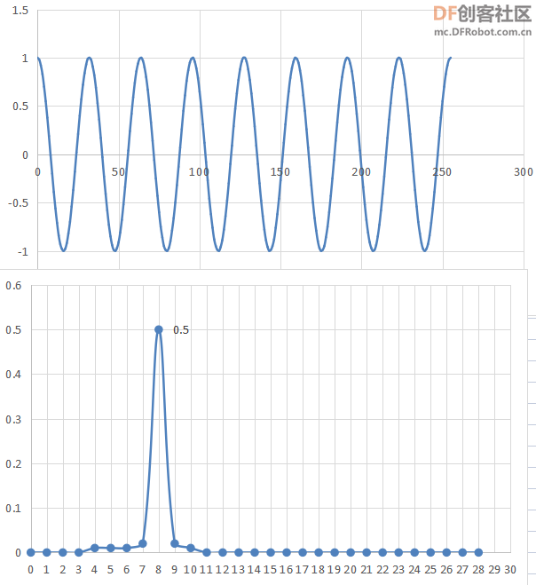
值得关注的是,自生成的256个元素的数组,默认为1s内记录的数据。数学中频率为f的余弦函数基础表达式为: cos(2 * pi * f * t )
代码中 cos(2.0 * M_PI * 8.0 * i/255.0) 意为i从0到255,t 自0到1.
最后发现,确实在8Hz处出现峰值,验证成功。
=================================================================
2023/7/8更新
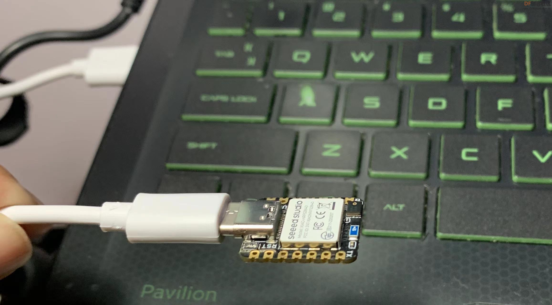
尝试使用XIAO SENSE自带的三轴加速度传感器来测试,方便起见,只用Z轴(垂直于板平面)。
在插着数据线状态下,像扇扇子一样挥动XIAO SENSE,如图:
- #include <avr/pgmspace.h>
- #include <math.h>
-
- #include "LSM6DS3.h"
- #include "Wire.h"
-
- LSM6DS3 myIMU(I2C_MODE, 0x6A); //I2C device address 0x6A
-
- #define N 256 // Number of samples for DFT
- float real[N];
- float imag[N];
- unsigned long start_t;
-
- void setup() {
- Serial.begin(9600);
- while (!Serial) {
- ; // Wait for serial port to connect
- }
- if (myIMU.begin() != 0) {
- //Serial.println("Device error");
- }
- else{
- //Serial.println("Device OK!");
- }
- }
-
- void loop() {
- start_t = millis();
- for (int i = 0; i < N; i++) {
- //float val = cos(2.0 * M_PI * 8.0 * i/255.0 * 2.0);
- float val = myIMU.readFloatAccelZ();
- real[i] = val; // Store sample in the real array
- imag[i] = 0; // Initialize imaginary part to 0
- delay(20);//每20ms记录一个数据,总计duration 255*20ms = 5100ms = 5.1s
- }
- Serial.println( millis() - start_t );
- // Perform DFT
- for (int k = 0; k < N; k++) {
- float sumReal = 0;
- float sumImag = 0;
-
- for (int t = 0; t < N; t++) {
- float angle = 2 * M_PI * t * k / N;
- sumReal += real[t] * cos(angle) + imag[t] * sin(angle);
- sumImag += -real[t] * sin(angle) + imag[t] * cos(angle);
- }
-
- // Normalize the result
- float magnitude = sqrt(sumReal * sumReal + sumImag * sumImag) / N;
-
- // Output the magnitude to the serial monitor
- Serial.print(k);
- Serial.print("\t");
- Serial.print(magnitude);
- Serial.print("\t");
- Serial.println(real[k]);
- }
-
- delay(5000); // Delay for 1 second before the next measurement
- }
慢速甩动测试:
视频地址:链接: https://pan.baidu.com/s/1Mu1BhBEesIPPW_tndhoTRQ?pwd=8888 提取码: 8888
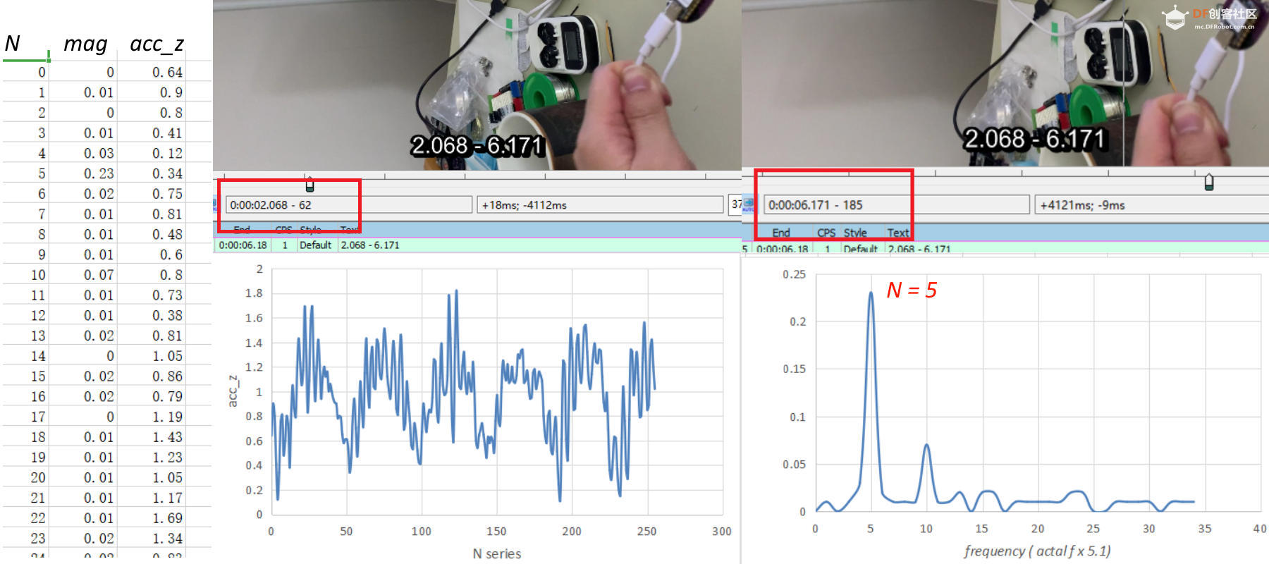
取4次甩动周期,时间自2.068 s 到 6.171 s,
时长4.103 s
平均周期取四位有效位数为
4.103 / 4 = 1.026 s
理论频率为0.9749 Hz。
记录的数据分析结果如上图:
左图为Z轴加速度数据,右图为傅里叶变换后结果:
#偶尔第一行N = 0 时数值很高,可以改为0。
根据结果,显示峰值在N = 5。
假定每次记录的数据间隔仅20ms,则记录256个数据总时长为255 * 20 ms = 5100 ms = 5.1 s
(见代码delay设定,实际总duration 应大于5.1s)
原代码中256个数据默认为1秒内记录的数据(见上例),故图中峰值5Hz应该缩小5.1倍
修正:
5 / 255 / 0.02 = 5 / 5.1 = 0.98 Hz
相较于理论频率 0.9749Hz 已非常接近。
-------------------------------------------------------------------------------------------------------------------------------------------------------------------------------------------------------
快速甩动测试:
视频地址:链接: https://pan.baidu.com/s/1UOCqrCCBoUgybaMapF1avA?pwd=8888 提取码: 8888
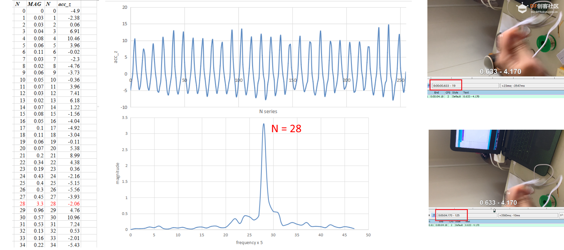
取20次甩动周期,时间自0.633 s 到 4.170 s,
时长3.537 s
平均周期取四位有效位数为
3.537 / 20 = 0.177 s
理论频率为5.655 Hz。
记录的数据分析结果如上图:
左图为Z轴加速度数据,右图为傅里叶变换后结果:
根据结果,显示峰值在N = 28.
修正:
28 / 255 / 0.02 = 28 / 5.1 = 5.49 Hz
相较于理论频率 5.655Hz 略小,误差2.9%。
------------------------------------------------------------------------------------------------------------------------------------------------------------------------------------------------------------
【值得继续讨论的内容】
1. 对于高频信号的处理可行性;
2. 验证复杂信号的适用性;3. 实际数据记录时间是否大于或小于5.1s;
| 


 沪公网安备31011502402448
 置顶卡
置顶卡 变色卡
变色卡 千斤顶
千斤顶


