|
LED炫彩时钟~
【效果图】

【介绍】
楼主也不免俗地做起了LED 时钟呢~看到了论坛里的这篇帖子,给脑洞点赞!我用的LED 圆盘是三个圆环拼起来的,LED 数量分别为12 ,16 ,24 。用12 个的那一圈表示了小时,在表示分钟的方法上犯难了,最后决定用十进制,用前六个LED灯表示十位数字,分别为0-5,以绿色为背景;用后十位代表个位数字,分别为0-9,以蓝色为背景;用最外一圈的闪烁代表秒针,颜色随机。上面的动图就是时间从1点36变成1点37的效果。
【视频】
视频效果一般,肉眼看的话,被点亮的led也是可以看清数字的,ipad mini1的摄像头果然不行
【硬件清单】 灯环/灯带/灯盘/灯珠
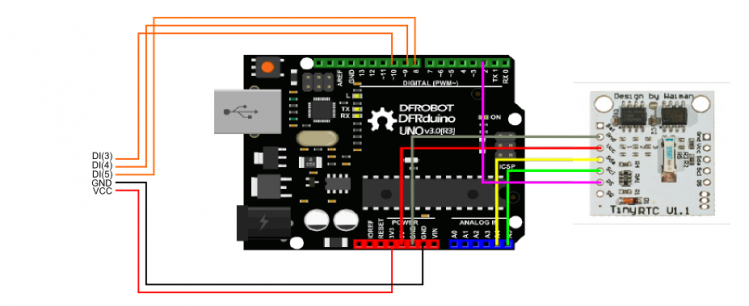
【连线图】 因为没有找到灯盘的SVG图就只在左侧标注了连线脚
【库文件】 在这个应用中我用到了LED的库以及时钟模块的库
【测试】 我们先需要用以下代码测试一下时钟模块看时间是否正确
- #include <Wire.h>
- #include <DS1307.h>
-
- String comdata = "";
- //store the current time data
- int rtc[7];
- //light pin
- int ledPin = 13;
- //initial light
- void setup()
- {
- DDRC |= _BV(2) | _BV(3); // POWER:Vcc Gnd
- PORTC |= _BV(3); // VCC PINC3
- pinMode(ledPin, OUTPUT);
- //initial baudrate
- Serial.begin(9600);
- //get current time
- RTC.get(rtc, true);
- RTC.SetOutput(DS1307_SQW32KHZ);
- }
-
- void loop()
- {
- int i;
- //get current time
- RTC.get(rtc, true);
- //print current time format : sec min hour week day month year
- for (i = 0; i < 7; i++)
- {
- Serial.print(rtc[i]);
- Serial.print(" ");
- }
- //blink the light
- Serial.println();
- digitalWrite(ledPin, HIGH);
- delay(500);
- digitalWrite(ledPin, LOW);
- delay(500);
- }
【代码】 - #include <Adafruit_NeoPixel.h>
- #include <Wire.h>
- #include <DS1307.h>
- #ifdef __AVR__
- #include <avr/power.h>
- #endif
-
- //store the current time data
- int rtc[7];
-
- #define PIN3 10
- #define PIN4 9
- #define PIN5 8
-
- int r, g, b;
-
- // Parameter 1 = number of pixels in round3
- // Parameter 2 = Arduino pin number (most are valid)
- // Parameter 3 = pixel type flags, add together as needed:
- // NEO_KHZ800 800 KHz bitstream (most NeoPixel products w/WS2812 LEDs)
- // NEO_KHZ400 400 KHz (classic 'v1' (not v2) FLORA pixels, WS2811 drivers)
- // NEO_GRB Pixels are wired for GRB bitstream (most NeoPixel products)
- // NEO_RGB Pixels are wired for RGB bitstream (v1 FLORA pixels, not v2)
-
- Adafruit_NeoPixel round3 = Adafruit_NeoPixel(12, PIN3, NEO_GRB + NEO_KHZ800);
- Adafruit_NeoPixel round4 = Adafruit_NeoPixel(16, PIN4, NEO_GRB + NEO_KHZ800);
- Adafruit_NeoPixel round5 = Adafruit_NeoPixel(24, PIN5, NEO_GRB + NEO_KHZ800);
-
- void setup() {
- //get current time
- RTC.get(rtc, true);
- RTC.SetOutput(DS1307_SQW32KHZ);
-
- round3.begin();
- round4.begin();
- round5.begin();
- // This initializes the NeoPixel library.
- Serial.begin(9600);
- }
-
- void loop() {
- //get current time
- int ten, unit, minutes, hours;
- RTC.get(rtc, true);
- //print current time format : sec min hour week day month year
- for (int i = 0; i < 7; i++)
- {
- Serial.print(rtc[i]);
- Serial.print(" ");
- minutes = rtc[1];
- hours = rtc[2];
- }
- unit = minutes%10;
- ten = int(minutes/10);
- if (hours >= 12) {
- hours = hours-12;
- }else{
- hours = rtc[2];
- }
-
- //minute
- round4.setPixelColor(ten, round4.Color(30,210,130));
- round4.setPixelColor(unit+6, round4.Color(30,150,200));
- round4.show();
- for (int i = 0; i < 6; i++)
- {
- round4.setPixelColor(i, round4.Color(1,12,8));
- }
- for (int i = 6; i < 16; i++)
- {
- round4.setPixelColor(i, round4.Color(1,9,12));
- }
-
- //hour
- round3.setPixelColor(hours, round3.Color(150,142,39));
- round3.show();
- for (int i = 0; i < 12; i++)
- {
- round3.setPixelColor(i, round3.Color(14,11,3));
- }
-
- //blink
- r = random(1,7);
- g = random(1,7);
- b = random(1,7);
- for (int i = 0; i < 24; i++){
- round5.setPixelColor(i, round5.Color(r,g,b)); // random color
- }
- round5.show();
- delay(500);
- for (int i = 0; i < 24; i++){
- round5.setPixelColor(i, round5.Color(0,0,0));
- }
- round5.show();
- delay(500);
- }
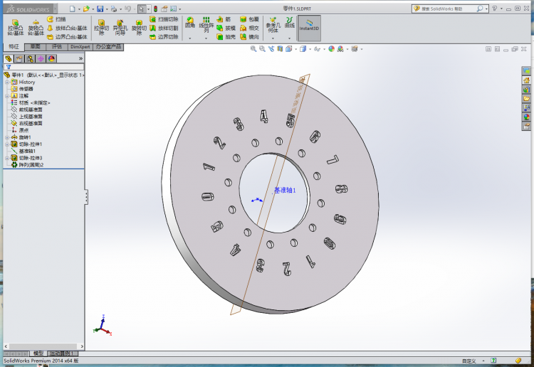
【3D外壳】用了SolidWorks做了一个外壳~在电脑上看觉得敲美丽,然而。。。 在和打印机较劲一整天之后它终于给我打出来一个还像样儿的外壳,楼主表示已经很安慰了。。。
|
|
|
|
|
|
|
|
|
|


 沪公网安备31011502402448

 置顶卡
置顶卡 变色卡
变色卡 千斤顶
千斤顶