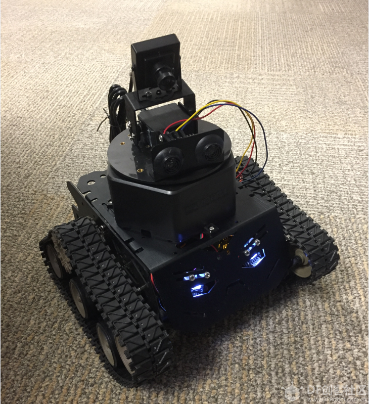
未来的愿景正在逐步成为现实。 或许, 机器人将会有一天接管整个世界,但是现在,我们仍然需要通过互联网对其进行远程控制。 在本文中,我们将创建一个 HTML 页面,以便帮助用户使用 MQTT 发送命令,进而控制机器人移动,并通过机器人身上的网络摄像头查看周围环境。 这种远程控制功能为我们在未来添加更多的特性奠定了基础。 图 1: 完全组装的 DFRobot Devastator Robot 注: Devastator 的电池组为 6 块 AA 电池,电压仅为 9V,如果该项目加载所有电机和摄像头,便不足以支持。 如果要达到本文的要求,必须串联一个 2 AA 电池组,以便使总电压达到 12V。
设置摄像头 在 Devastator Robot 上,使用 OTG USB 适配器将 USB 网络摄像头插入 micro OTG USB 端口,并将另一根线缆插入电脑上的其他 micro USB 端口。 要确保 USB 网络摄像头正常工作,请在串行连接中键入: (使用 PuTTY) 屏幕上应显示与下面类似的一行:
- crw-rw---- 1 root video 81, 0 May 6 22:36 /dev/video0
否则,如果显示下面的一行,则说明未发现摄像头。 - ls: cannot access /dev/video0: No such file or directory
接下来,在英特尔® Edison 模块上安装 mjpeg-streamer 库。 向 base-feeds.conf 添加以下行即可: - echo "src/gz all <a href="http://repo.opkg.net/edison/repo/all" target="_blank">http://repo.opkg.net/edison/repo/all</a>
- src/gz edison <a href="http://repo.opkg.net/edison/repo/edison" target="_blank">http://repo.opkg.net/edison/repo/edison</a>
- src/gz core2-32 <a href="http://repo.opkg.net/edison/repo/core2-32" target="_blank">http://repo.opkg.net/edison/repo/core2-32</a>" >> /etc/opkg/base-feeds.conf
更新存储卡索引: 安装: - opkg install mjpg-streamer
要启动数据流: - mjpg_streamer -i "input_uvc.so -n -f 10 -r 400x400" -o "output_http.so -p 8080 -w ./www"
请注意,帧率 (-f 10) 和尺寸 (400x400) 受到一定的限制,以便降低功耗和计算需求,从而确保在不停止数据流的情况下获得最新的图像。 此外,启动的时候还需要启动摄像头,以便准备好使用。 首先在/home/root/ 目录中创建一个脚本。 将以下内容添加至脚本。 - #!/bin/sh
- mjpg_streamer -i "input_uvc.so -n -f 10 -r 400x400" -o "output_http.so -p 8080 -w ./www"
- chmod +x /home/root/ cameraScript.sh
- chmod +x cameraScript.sh
- update-rc.d cameraScript.sh defaults
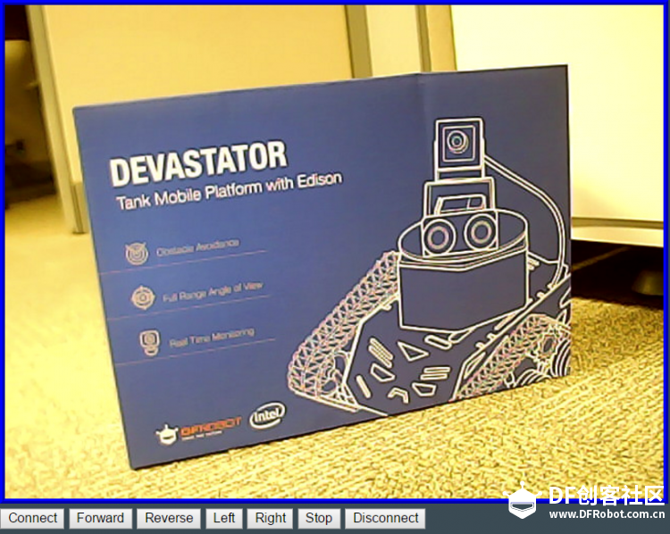
要确保正常工作,请重启英特尔® Edison 模块。 (该步骤假设其已经过配置并连接至 Wi-Fi)。 HTML 网页要远程控制机器人,可以创建一个简单的 HTML 网页。该网页可以轻松地捆绑至网络摄像头的数据流并兼容多种不同的平台。 在电脑上的相同位置会有一个index.html文件和一个script.js 文件。 双击index.html 文件将会启动该网页。
图 2: HTML 页面截图(网络摄像头试图和 控制按钮) index.html 文件代码如下所示。 由于机器人使用 MQTT,而且我们需要某些定制方法,因此我们包括了mqttws31.js和我们自己的script.js。 此外,我们还需要一个包含 web 数据流的对象,以及一些能够控制机器人的按钮。
- <!DOCTYPE html>
- <html>
-
- <head>
- <title>NodeJS Starter Application</title>
- <meta charset="utf-8">
- <meta http-equiv="X-UA-Compatible" content="IE=edge">
- <meta name="viewport" content="width=device-width, initial-scale=1">
- <link rel="stylesheet" href="stylesheets/style.css">
- <script src="https://cdnjs.cloudflare.com/ajax/libs/paho-mqtt/1.0.1/mqttws31.js" type="text/javascript"></script>
- <script src="script.js"></script>
- </head>
-
- <body>
- <div>
- <object type="text/html" data="http://192.168.1.104:8080/?action=stream" width="640px" height="480px" style="overflow:auto;border:5px ridge blue">
- </object>
- </div>
- <div>
- <input type="button" value="Connect" id="connect"></input>
- <input type="button" value="Forward" id="forwardButton"></input>
- <input type="button" value="Reverse" id="reverseButton"></input>
- <input type="button" value="Left" id="leftButton"></input>
- <input type="button" value="Right" id="rightButton"></input>
- <input type="button" value="Stop" id="stopButton"></input>
- <input type="button" value="Disconnect" id="disconnect"></input>
- <div id="messages"></div>
- </div>
- </body>
-
-
- </html>
script.js将会突出显示当前的命令按钮,并处理 MQTT 连接和订阅逻辑。 注意script.js中的客户端实例行: - var client = new Paho.MQTT.Client("broker.hivemq.com", 8000, "clientId");
我们使用broker.hivemq.com作为我们的 MQTT 服务器。 这项服务是免费的,并且可以通过其服务建立您自己的代理。 clientId对于每个客户端来说必须是唯一的,因此请对其进行更改,比如添加某些随机字符和数字。机器人用于订阅和发布的主题是dfrobotControl,但是您可以根据自己的目的进行修改。 - function moveForward()
- {
- clearButtons();
- document.getElementById("forwardButton").style.color = "red";
- };
- function moveReverse()
- {
- clearButtons();
- document.getElementById("reverseButton").style.color = "red";
- };
- function moveLeft()
- {
- clearButtons();
- document.getElementById("leftButton").style.color = "red";
- };
- function moveRight()
- {
- clearButtons();
- document.getElementById("rightButton").style.color = "red";
- };
- function moveStop()
- {
- clearButtons();
- document.getElementById("stopButton").style.color = "red";
- };
- function clearButtons()
- {
- document.getElementById("forwardButton").style.color = "black";
- document.getElementById("reverseButton").style.color = "black";
- document.getElementById("leftButton").style.color = "black";
- document.getElementById("rightButton").style.color = "black";
- document.getElementById("stopButton").style.color = "black";
- };
-
-
- // Create a client instance
- var client = new Paho.MQTT.Client("broker.hivemq.com", 8000, "clientId");
-
- // called when the client loses its connection
- client.onConnectionLost = function (responseObject) {
- alert("connection lost: " + responseObject.errorMessage);
- };
-
- //Connect Options
- var options = {
- timeout: 3,
- //Gets Called if the connection has sucessfully been established
- onSuccess: function () {
- alert("Connected");
- //and subscribe to the topic
- client.subscribe('dfrobotControl/#', {qos: 2});
- alert('Subscribed');
- },
- //Gets Called if the connection could not be established
- onFailure: function (message) {
- alert("Connection failed: " + message.errorMessage);
- }
- };
-
- //Publish the message to the topic
- var publish = function (payload, topic, qos) {
- var message = new Paho.MQTT.Message(payload);
- message.destinationName = topic;
- message.qos = qos;
- client.send(message);
-
- }
代码示例 2:用于 HTML 页面的 script.js 文件 Devastator 使用面向英特尔® Edison 模块的 Romeo 开发板,默认情况下通过 Arduino* IDE 进行编程。 在 Arduino sketch 中,我们需要订阅 MQTT 主题,以便接收并执行相关的命令。 网络摄像头已经准备就绪,但我们需要设置英特尔® Edison 模块的静态 IP 地址,并将其连接至 Wi-Fi* 网络。 完成这样的设置后,网络摄像头的 IP 便一直与网页的 IP 保持相同。 前端 LED 用作状态指示灯。 成功完成 Wi-Fi 连接后,机器人的右侧 LED 指示灯将会亮起。 当 MQTT 成功连接和订阅后,机器人的左侧 LED 指示灯将会亮起。
- #include <SPI.h>
- #include <WiFi.h>
- #include <PubSubClient.h>
- #include <DFRobot.h>
- #include <IIC1.h>
-
- // WiFi Login
- IPAddress ip(192, 168, 1, 104);
- char ssid[] = "wifiname"; // your network SSID (name)
- char pass[] = "wifipassword"; // your network password
- const char* server = "broker.mqttdashboard.com";
-
- // WiFi connection
- WiFiClient wifiClient;
- int status = WL_IDLE_STATUS; // the Wifi radio's status
-
- #define leftLEDPin 7
- #define rightLEDPin 10
-
- DFrobotEdison MotorLeft;
- DFrobotEdison MotorRight;
- void callback(char* topic, byte* payload, unsigned int length) {
- Serial.print("Message arrived [");
- Serial.print(topic);
- Serial.print("] ");
- String message= "";
- for (int i=0;i<length;i++) {
- Serial.print((char)payload);
- message= message + (char)payload;
- }
- Serial.println();
- String forward= "forward";
- if (message.equals("forward") == 1) {
- Serial.println("Forward!!!");
- motorForward();
- }
- if (message.equals("reverse") == 1) {
- motorBackward();
- Serial.println("reverse!!!");
- }
- if (message.equals("left") == 1) {
- motorLeft();
- Serial.println("left!!!");
- }
- if (message.equals("right") == 1) {
- motorRight();
- Serial.println("right!!!");
- }
- if (message.equals("stop") == 1) {
- motorStop();
- }
- }
-
- // PubSub Client.
- PubSubClient client(server, 1883, callback , wifiClient);
连接到 MQTT 服务器时,务必为英特尔® Edison 模块选择唯一的clientID,并在需要的时候更改主题。 要实现这一点,可以更新client.connect("clientID "))和client.subscribe("dfrobotControl")行。 - void reconnectMQTT() {
- // Loop until we're reconnected
- digitalWrite(leftLEDPin, LOW);
- motorStop();
- while (!client.connected()) {
- Serial.print("Attempting MQTT connection...");
- // Attempt to connect
- if (client.connect("clientID ")) {
- Serial.println("connected");
- // ... and resubscribe
- client.subscribe("dfrobotControl");
- digitalWrite(leftLEDPin, HIGH);
- } else {
- Serial.print("failed, rc=");
- Serial.print(client.state());
- Serial.println(" try again in 5 seconds");
- // Wait 5 seconds before retrying
- delay(5000);
- }
- }
- }
-
- void reconnectWiFi() {
- // Loop until we're reconnected
- digitalWrite(rightLEDPin, LOW);
- digitalWrite(leftLEDPin, LOW);
- motorStop();
- status = WiFi.begin(ssid, pass);
- while(!(status == WL_CONNECTED)){
- Serial.println("WiFi Failed!");
- status = WiFi.begin(ssid, pass);
- delay(5000);
- }
- Serial.println("WiFi Connected!");
- digitalWrite(rightLEDPin, HIGH);
- }
-
- void setup()
- {
- Serial.begin(9600);
-
- Serial.println("Init the sensor");
-
- //Initilize Pin Mode
- pinMode(rightLEDPin, OUTPUT);
- pinMode(leftLEDPin,OUTPUT);
- digitalWrite(rightLEDPin, LOW);
- digitalWrite(leftLEDPin, LOW);
-
- //Initilize Motor Drivers
- MotorLeft.begin(M2);
- MotorRight.begin(M1);
-
- WiFi.config(ip);
- status = WiFi.begin(ssid, pass);
- while(!(status == WL_CONNECTED)){
- Serial.println("WiFi Failed!");
- status = WiFi.begin(ssid, pass);
- delay(5000);
- }
- Serial.println("WiFi Connected!");
- digitalWrite(rightLEDPin, HIGH);
- }
-
- void loop()
- {
- client.loop();
- if (!client.connected()) {
- reconnectMQTT();
- }
- if(WiFi.status()!= WL_CONNECTED){
- reconnectWiFi();
- }
- delay(1000);
-
- }
最后是控制机器人移动的方法。 - void motorBackward()
- {
- motorStop();
- MotorLeft.setDirection(ANTICLOCKWISE);
- MotorRight.setDirection(ANTICLOCKWISE);
- for(int i=0;i<150;i+=10)
- {
- MotorLeft.setSpeed(i);
- MotorRight.setSpeed(i);
- delay(20);
- }
- }
-
-
- void motorForward()
- {
- motorStop();
- MotorLeft.setDirection(CLOCKWISE);
- MotorRight.setDirection(CLOCKWISE);
- for(int i=0;i<150;i+=10)
- {
- MotorLeft.setSpeed(i);
- MotorRight.setSpeed(i);
- delay(20);
- }
- }
-
- inline void motorLeft()
- {
- motorStop();
- MotorLeft.setDirection(ANTICLOCKWISE);
- MotorRight.setDirection(CLOCKWISE);
- for(int i=0;i<150;i+=10)
- {
- MotorLeft.setSpeed(i);
- MotorRight.setSpeed(i);
- delay(20);
- }
- }
-
- inline void motorRight()
- {
- motorStop();
- MotorLeft.setDirection(CLOCKWISE);
- MotorRight.setDirection(ANTICLOCKWISE);
- for(int i=0;i<150;i+=10)
- {
- MotorLeft.setSpeed(i);
- MotorRight.setSpeed(i);
- delay(20);
- }
- }
-
-
- inline void motorStop()
- {
- MotorLeft.setSpeed(0);
- MotorRight.setSpeed(0);
- delay(50);
- }
代码示例 3: 控制机器人的 Arduino sketch 现在,我们可以借助使用 MQTT 的简单网页来远程控制机器人,并通过网络摄像头查看其移动方向。 在此基础之上,我们可以在机器人中构建更多的特性,例如面积测绘或者摄像头的平移和倾斜。
更多机器人项目
作者介绍 Whitney Foster 是英特尔公司软件解决方案事业部的一名工程师,负责大规模物联网项目的支持工作。
声明
本文档不代表英特尔公司或其它机构向任何人明确或隐含地授予任何知识产权。 英特尔明确拒绝所有明确或隐含的担保,包括但不限于对于适销性、特定用途适用性和不侵犯任何权利的隐含担保,以及任何对于履约习惯、交易习惯或贸易惯例的担保。 本文包含尚处于开发阶段的产品、服务和/或流程的信息。 此处提供的信息可随时改变而毋需通知。 联系您的英特尔代表,了解最新的预测、时间表、规格和路线图。 本文件所描述的产品和服务可能包含使其与宣称的规格不符的设计缺陷或失误。 这些缺陷或失误已收录于勘误表中,可索取获得。 英特尔、Intel 标识、Intel RealSense 和英特尔实感是英特尔在美国和/或其他国家的商标。
* 其他的名称和品牌可能是其他所有者的资产。 **该示例源代码根据英特尔示例源代码许可协议发布。 英特尔公司 © 2016 年版权所有。 |
|
|
|
|
|
|
|
|
|


 沪公网安备31011502402448
 置顶卡
置顶卡 变色卡
变色卡 千斤顶
千斤顶


