|
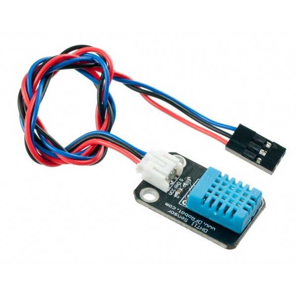
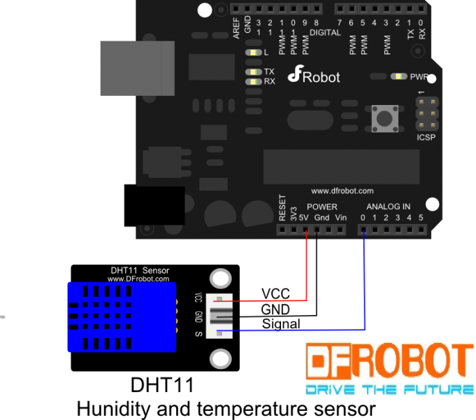
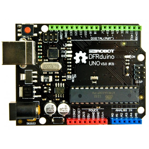
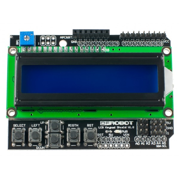
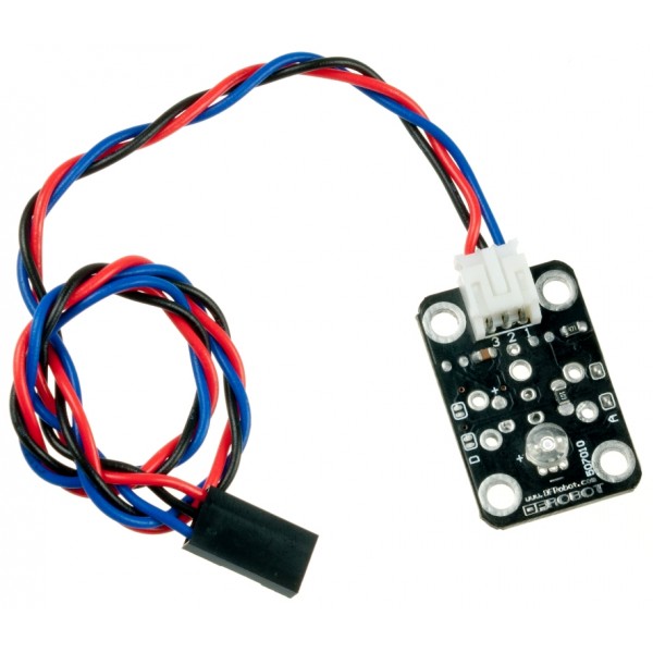
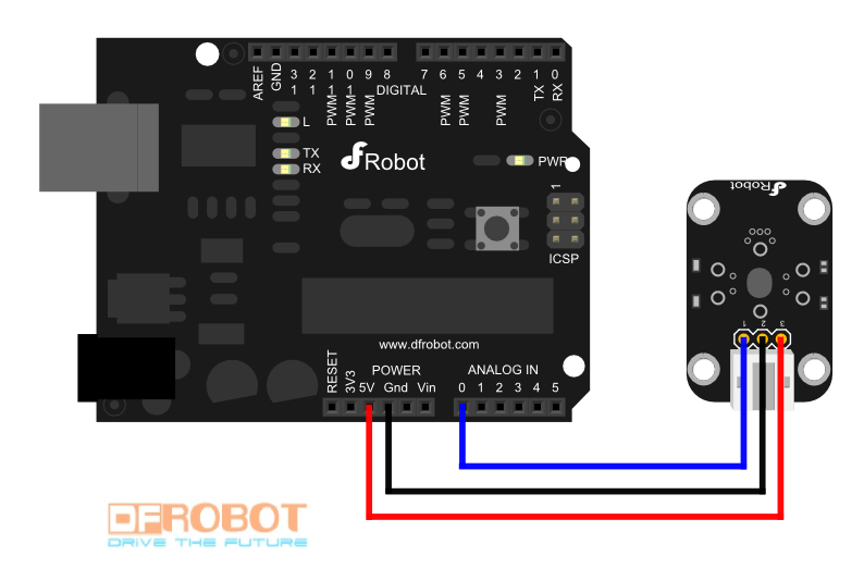
温度、湿度、亮度测量仪 介绍: 大家好,我是Jason Chen,一个来自上海的学生。由于是电子信息专业的学生,所以希望能够应用课堂知识做些东西出来。但由于这是第一次接触 Arduino平台,所以先做一个简单的小东西和大家分享一下。今天我做的这个东西是一个比较常见的温度、湿度、亮度测量仪。在现在这个社会上到处都需要这么一个这类装置,甚至家中都可以有这么一个小型的测量仪来监控家里的环境。 通过一个温度湿度传感器和一个亮度传感器,我能读到相关数值。再通过一个显示屏将读取到的数据显示出来。制作三个显示页面,分别显示温度、湿度、亮度和传感器上读到的数据。并用上下按键切换显示页面。 硬件: 软件: l Arduino1.0.5 l LiquidCrystallibrary 教程: 1、 连接硬件 首先将arduino板和带扩展板的lcd屏幕连在一起。将扩展板背后的长脚接口与arduino板上的接口对其插紧 然后分别将一个温度湿度传感器和一个亮度传感器连接在扩展板的右下角的模拟接口上。由于拿到的传感器是将三根导线排在一起的,但是顺序却跟扩展板上的接口顺序不一样。这个时候就需要将三个线的顺序拔出调整,并对好黑线接地,红线接5V,蓝线接模拟口。需要注意的是,uno板上有六个模拟口,但是由于扩展板上有按键,占据了analog 0,只剩下5个模拟口可供感应器连接。
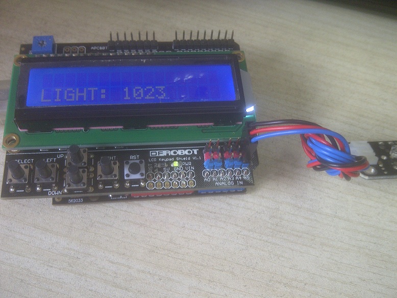
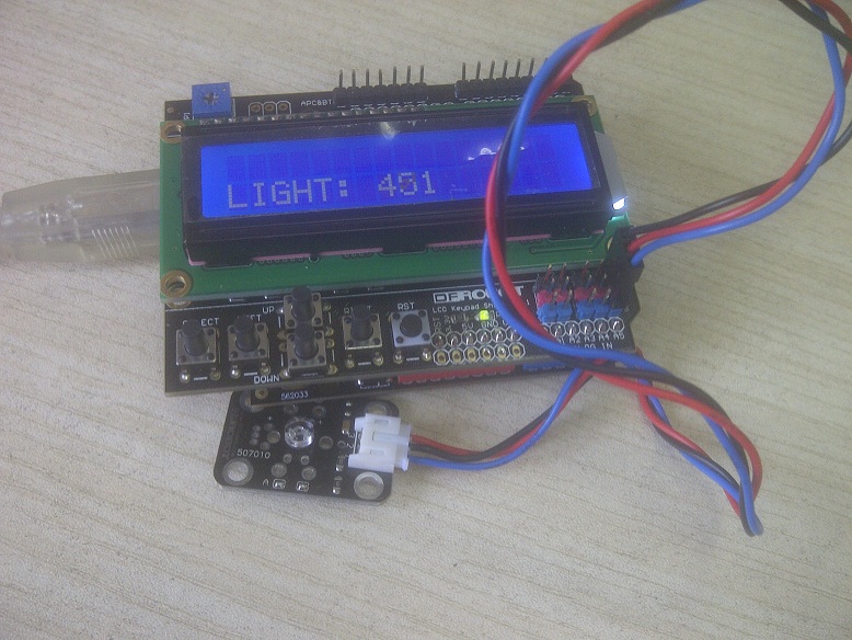
分别组装好的时候是这样的: 2、 编程 首先为了熟悉两个感应器的运行,先将产品wiki上的sample code输入arduino 1.0.5中,并upload进arduino板中。如果连接正确这时候屏幕上应该是有正确的示数。如果不能正确显示请检查sample code中定义的感应器的接口是否正确(默认的接口是0,但扩展板上的模拟0接口已被按键占用) 我自己编写的代码是这样的:
- #include <LiquidCrystal.h>
-
- LiquidCrystal lcd(8, 9, 4, 5, 6, 7);
-
- int n,m;
- // define some values used by the panel and buttons
- int lcd_key = 0;
- int adc_key_in = 0;
- #define btnRIGHT 0
- #define btnUP 1
- #define btnDOWN 2
- #define btnLEFT 3
- #define btnSELECT 4
- #define btnNONE 5
-
- #define DHT11_PIN 1
-
- // read the buttons
- int read_LCD_buttons()
- {
-
- adc_key_in = analogRead(0); // read the value from the sensor
- // my buttons when read are centered at these valies: 0, 144, 329, 504, 741
- // we add approx 50 to those values and check to see if we are close
- if (adc_key_in > 1000) return btnNONE; // We make this the 1st option for speed reasons since it will be the most likely result
- // For V1.1 us this threshold
- if (adc_key_in < 50) return btnRIGHT;
- if (adc_key_in < 250) return btnUP;
- if (adc_key_in < 450) return btnDOWN;
- if (adc_key_in < 650) return btnLEFT;
- if (adc_key_in < 850) return btnSELECT;
- return btnNONE; // when all others fail, return this...
- }
-
- byte read_dht11_dat()
- {
- byte i = 0;
- byte result=0;
- for(i=0; i< 8; i++)
- {
- while(!(PINC & _BV(DHT11_PIN)))
- {}; // wait forever until anlog input port 0 is '1' (NOTICE: PINC reads all the analog input ports
- //and _BV(X) is the macro operation which pull up positon 'X'to '1' and the rest positions to '0'. it is equivalent to 1<<X.)
- delayMicroseconds(30);
- if(PINC & _BV(DHT11_PIN)) //if analog input port 0 is still '1' after 30 us
- result |=(1<<(7-i)); //this position is 1
- while((PINC & _BV(DHT11_PIN))); // wait '1' finish
- }
- return result;
- }
-
- void setup() {
- Serial.begin(9600);
- Serial.println("Start");
- lcd.begin(16, 2);
-
- DDRC |= _BV(DHT11_PIN); //let analog port 0 be output port
- PORTC |= _BV(DHT11_PIN);
- }
- void loop() {
- lcd.setCursor(0,0);
- lcd_key = read_LCD_buttons();
- Serial.println(lcd_key);
-
- byte dht11_dat[5];
- byte dht11_in;
- byte i;// start condition
-
- PORTC &= ~_BV(DHT11_PIN); // 1. pull-down i/o pin for 18ms
- delay(18);
- PORTC |= _BV(DHT11_PIN); // 2. pull-up i/o pin for 40us
- delayMicroseconds(1);
- DDRC &= ~_BV(DHT11_PIN); //let analog port 0 be input port
- delayMicroseconds(40);
-
- dht11_in = PINC & _BV(DHT11_PIN); // read only the input port 0
- if(dht11_in)
- {
- Serial.println("dht11 start condition 1 not met"); // wait for DHT response signal: LOW
- delay(1000);
- return;
- }
- delayMicroseconds(80);
- dht11_in = PINC & _BV(DHT11_PIN); //
- if(!dht11_in)
- {
- Serial.println("dht11 start condition 2 not met"); //wair for second response signal:HIGH
- return;
- }
-
- delayMicroseconds(80);// now ready for data reception
- for (i=0; i<5; i++)
- { dht11_dat[i] = read_dht11_dat();} //recieved 40 bits data. Details are described in datasheet
-
- DDRC |= _BV(DHT11_PIN); //let analog port 0 be output port after all the data have been received
- PORTC |= _BV(DHT11_PIN); //let the value of this port be '1' after all the data have been received
- byte dht11_check_sum = dht11_dat[0]+dht11_dat[1]+dht11_dat[2]+dht11_dat[3];// check check_sum
- if(dht11_dat[4]!= dht11_check_sum)
- {
- Serial.println("DHT11 checksum error");
- }
-
- switch (lcd_key)
- {
- case btnUP:
- {
- n=n+1;
- if(n==3)n=0;
- break;
- }
- case btnDOWN:
- {
- n=n-1;
- if(n==-1)n=2;
- break;
- }
- }
- switch(n)
- {
- case 0:{
- lcd.clear();
- lcd.write("TEMPERATURE:");
- Serial.println("TEMPERATURE");
- lcd.print(dht11_dat[2], DEC);
- lcd.print(".");
- lcd.print(dht11_dat[3], DEC);
- lcd.println("C ");
- delay(200);
- break;
- }
- case 1:{
- lcd.clear();
- lcd.write("HUMIDITY:");
- Serial.println("HUMIDITY");
- lcd.print(dht11_dat[0], DEC);
- lcd.print(".");
- lcd.print(dht11_dat[1], DEC);
- lcd.print("% ");
- delay(200);
- break;
- }
- case 2:{
- lcd.clear();
- lcd.write("LIGHT:");
- Serial.println("LIGHT");
- int sensorValue = analogRead(A5);
- lcd.setCursor(7,0);
- lcd.print(sensorValue);
- delay(200);
- break;
- }
- }
- }
-
总结: 在做每个小产品之前,首先得熟悉每个材料的工作原理,通过查询每个器件的wiki,了解原理图和连接方式。例如将带键盘扩展板的1602 屏幕连在uno板之后,运行samplecode将在屏幕上显示按键信息和运行时间。在连接亮度传感器或温度湿度传感器的时候需要注意导线的排列方式。以及samplecode默认的接口和真实接的是不同的。此处的感应器的接口将在编写代码的时候修改到。编写代码的时候主要用到两个传感器和屏幕按键的代码。但是在合并的时候却会有许多的问题。我并没有使用菜单库,而是使用了最基本的switch语句,分别设置三个显示页面分别为n = 0、1、2,在按UP键的时候执行n+1,按down的时候执行n-1,并判断当n=3的时候执行n=0,当n=-1的时候执行n=2,这样就能够变成循环切换菜单。这个时候还需要在每个显示页面输入一个清屏代码,不然的话,再切换的时候,会出现上一个页面的残留显示。这时候还会出现一个问题,按一次键的时候会执行好几次循环,导致菜单不停的跳。这个时候就需要设置按键释放检测,判断按键是否是一直按住,否则时间过长就会导致不停的做循环。(其实这一步我自己还没有在代码中体现出来,希望大家能提供一些意见) 这是我第一次发表文章,还有很多改进的地方,希望大家能共同学习,共同进步!
| 


 沪公网安备31011502402448
 置顶卡
置顶卡 变色卡
变色卡 千斤顶
千斤顶


