|
4108| 0
|
[项目] Beetle 树莓派RP2350测评1:肌电传感控制机器人 |
|
本帖最后由 Anders项勇 于 2025-5-17 22:06 编辑 【项目背景】 这次很荣幸得到了Beetle 树莓派RP2350测评机会。这次我计划用RP2350来做一个用肌电传感器控制机器人的项目。 【硬件介绍】 Beetle RP2350可穿戴嵌入式开发板是一款基于Raspberry Pi RP2350微控制器的高性能迷你开发板,专为嵌入式开发、物联网设备和可穿戴应用设计。其独特的双核双架构设计(支持 Arm Cortex-M33或Hazard3 RISC-V内核)为开发者提供灵活的性能配置。其小巧的尺寸(25mm x 20.5mm,约硬币大小)和高度集成的设计,使其成为对空间和便携性要求高的嵌入式应用和可穿戴设备的理想选择。 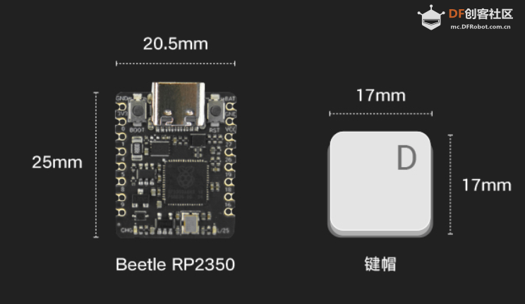 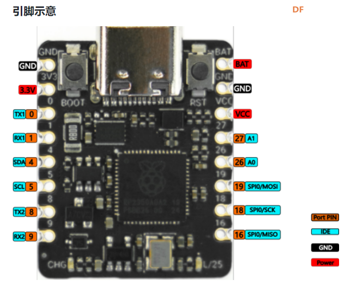 【方案设计】 计划用肌电传感器获取手臂肌肉握紧、放松的信号,RP2350的程序检测到信号后通过串口发送信息给sparrow控制板,sparrow调制红外信号遥控机器人动作。 【制作过程】 1.RP2350与肌电传感器编程: 肌电传感器模块 Analog EMG Sensor by OYMotion通过检测人体的表面肌电信号(sEMG),进而反应出人体肌肉和神经的活动情况。本传感器模块集成了滤波、放大电路,将范围在±1.5mV内的微弱人体表面肌电信号进行1000倍放大,并通过差分输入、模拟滤波电路的方式对噪音(特别是工频干扰)进行有效抑制。输出信号为模拟量形式,以1.5V为基准电压,0~3.0V量程的输出。输出信号的大小取决于选定肌肉的活动量,输出信号的波形可显著指示被观察位置皮下肌肉的情况,方便做肌电信号的分析与研究,如使用Arduino作为控制器检测肌肉活动情况,如肌肉是否紧绷,强度如何,是否疲劳等。 需要EMGFilters库文件https://github.com/yuyouliang/EMG_Filter  本代码中,threshold变量的值默认为0,表示处于校准模式。改成非零值,则退出校准模式。因此,如要重新进行校准,将代码中的threshold变量改成0即可,即:unsigned long threshold = 0;上传代码至arduino控制板中,然后打开arduino IDE的Serial Plotter,观察y轴数值的最大值。轻轻的握紧拳头,再轻轻的松开拳头,如此循环。观察Serial Plotter中y轴出现的最大值并记录之。这里测得最大100,最大值+100,提升抗干扰能力,所以threshold改为200,注意RP2350如果插再笔记本上供电,把笔记本电源拔掉,避免交流信号的干扰。 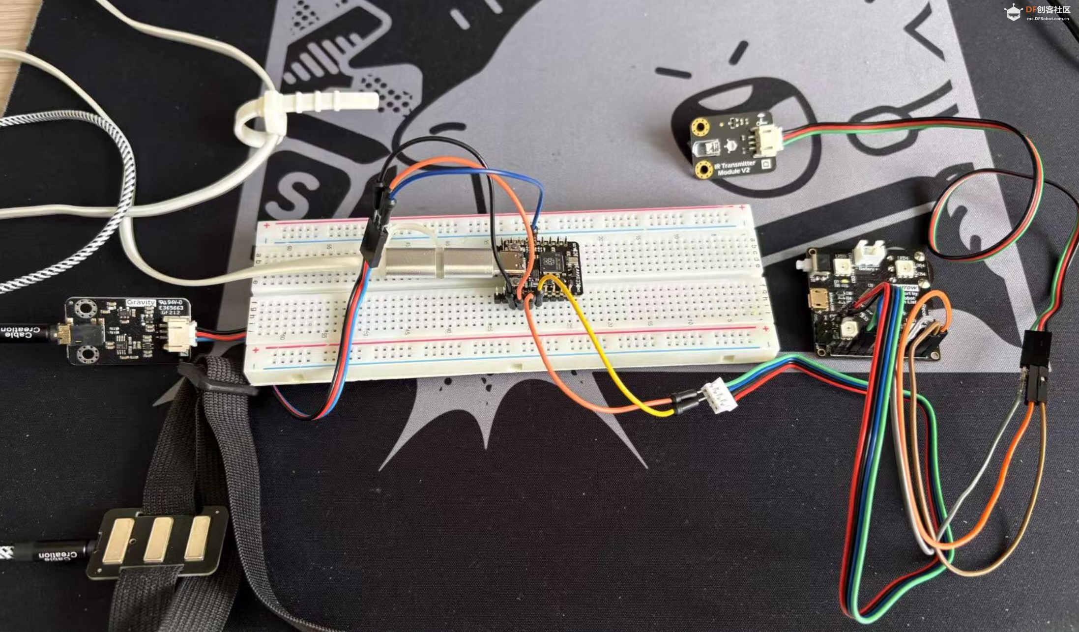 【肌电传感器计数视频】 RP2350的Arduino代码如下: #if defined(ARDUINO) && ARDUINO >= 100 #include "Arduino.h" #else #include "WProgram.h" #endif #include "EMGFilters.h" #define SensorInputPin A1 //sensor input pin number /* Define the `threshold` variable as 0 to calibrate the baseline value of input sEMG signals first. After wiring the sEMG sensors to the Arduino board, wear the sEMG sensors. Relax your muscles for a few seconds, you will be able to see a series of squared sEMG signals values get printed on your serial terminal. Choose the maximal one as the baseline by setting the `threshold` variable. Then rebuild this project. The `envelope`, which is the squared sEMG signal data, will be printed to the serial line. The developer can plot it using the Arduino SerialPlotter. Note: After calibration, Any squared value of sEMG sigal below the baseline will be treated as zero. It is recommended that you do calibration every time you wear the sEMG sensor. */ unsigned long threshold = 200; // threshold: Relaxed baseline values.(threshold=0:in the calibration process) unsigned long EMG_num = 0; // EMG_num: The number of statistical signals EMGFilters myFilter; /* Set the input frequency. The filters work only with fixed sample frequency of `SAMPLE_FREQ_500HZ` or `SAMPLE_FREQ_1000HZ`. Inputs at other sample rates will bypass */ SAMPLE_FREQUENCY sampleRate = SAMPLE_FREQ_500HZ; /* Set the frequency of power line hum to filter out. For countries with 60Hz power line, change to "NOTCH_FREQ_60HZ" */ NOTCH_FREQUENCY humFreq = NOTCH_FREQ_50HZ; void setup() { myFilter.init(sampleRate, humFreq, true, true, true); Serial.begin(115200); Serial1.begin(115200); //物理串口1 } void loop() { int data = analogRead(SensorInputPin); int dataAfterFilter = myFilter.update(data); // filter processing int envelope = sq(dataAfterFilter); //Get envelope by squaring the input envelope = (envelope > threshold) ? envelope : 0; // The data set below the base value is set to 0, indicating that it is in a relaxed state /* if threshold=0,explain the status it is in the calibration process,the code bollow not run. if get EMG singal,number++ and print */ if (threshold > 0) { if (getEMGCount(envelope)) { EMG_num++; Serial.print("EMG_num: "); Serial.println(EMG_num); Serial1.print("w"); //给机器人命令 } } else { Serial.println(envelope); Serial1.print("s"); //给机器人命令 } delayMicroseconds(500); } /* if get EMG signal,return 1; */ int getEMGCount(int gforce_envelope) { static long integralData = 0; static long integralDataEve = 0; static bool remainFlag = false; static unsigned long timeMillis = 0; static unsigned long timeBeginzero = 0; static long fistNum = 0; static int TimeStandard = 200; /* The integral is processed to continuously add the signal value and compare the integral value of the previous sampling to determine whether the signal is continuous */ integralDataEve = integralData; integralData += gforce_envelope; /* If the integral is constant, and it doesn't equal 0, then the time is recorded; If the value of the integral starts to change again, the remainflag is true, and the time record will be re-entered next time */ if ((integralDataEve == integralData) && (integralDataEve != 0)) { timeMillis = millis(); if (remainFlag) { timeBeginzero = timeMillis; remainFlag = false; return 0; } /* If the integral value exceeds 200 ms, the integral value is clear 0,return that get EMG signal */ if ((timeMillis - timeBeginzero) > TimeStandard) { integralDataEve = integralData = 0; return 1; } return 0; } else { remainFlag = true; return 0; } } 2.sparrow与红外发射管编程: Sparrow也是功能强大的控制器,是Arduino Leonardo的高度集成版本,具备和Leonardo类似的强大应用能力,支持兼容Arduino能用的所有编程软件,它搭载一颗ATmega32U4主控芯片。这里主要用到Sparrow稳定的时钟频率调制特定的红外线信号(非标准制式)控制一个机器人。直接用RP2350控制机器人应该也是可以的,但RP2350主频时钟太高,测试下来作为时钟参考误差太大,但可以使用LEDC控制模块(特指其PWM脉冲宽度调制)作为时钟参考,可是实际用代码测试执行机器人没有反应,不知道哪里有问题,写的不对,只好暂时作罢。现在直接用Sparrow接收RP2350的串口信息来控制机器人。 Sparrow的Arduino代码如下: //-------------------动作编码------------------------- #define forward 898819 #define backward 964611 #define sideright 703491 #define sideleft 637699 #define p1 922368 #define k1 991744 #define g1 602624 #define zero 1034752 #define hp 775424 #define totallength 22 #define channelstart 0 #define commandstart 4 #define channellength 4 #define commandlength 18 #define headerlower 2300 #define headernom 2550 #define headerupper 2800 #define zerolower 300 #define zeronom 380 #define zeroupper 650 #define onelower 800 #define onenom 850 #define oneupper 1100 #define highnom 630 #define TXpin A1 #define RXpin 2 boolean bit2[totallength]; unsigned long buttonnum; unsigned long power2(int power){ unsigned long integer=1; for (int i=0; i<power; i++){ integer*=2; } return integer; } void ItoB(unsigned long integer, int length){ for (int i=0; i<length; i++){ if ((integer / power2(length-1-i))==1){ integer-=power2(length-1-i); bit2=1; } else bit2=0; } } unsigned long BtoI(int start, int numofbits, boolean bit[]){ unsigned long integer=0; int i=start; int n=0; while(n<numofbits){ integer+=bit*power2((numofbits-n-1)); i++; n++; } Serial.println(); return integer; } void oscWrite(int pin, int time) { //频率38khz for(int i = 0; i < (time / 52) - 1; i++){ //预分频器 digitalWrite(pin, HIGH); delayMicroseconds(13); digitalWrite(pin, LOW); delayMicroseconds(13); } } void buttonwrite(int txpin, unsigned long integer){ ItoB(integer, 22); oscWrite(txpin, headernom); for(int i=0;i<totallength;i++){ if (bit2==0)delayMicroseconds(zeronom); else delayMicroseconds(onenom); oscWrite(txpin, highnom); } delay(205); } void setup() { Serial.begin(38400); //Serial用于USB的虚拟串口 Serial.println("Analyze Isobot IR Remote"); Serial1.begin(115200); //Serial1用于物理串口 pinMode(RXpin, INPUT); pinMode(TXpin, OUTPUT); } void loop(){ if(Serial1.available()>0){ char switcher= Serial1.read(); switch (switcher){ case 'w': buttonwrite(TXpin, forward); break; case 's': buttonwrite(TXpin, backward); break; case 'a': buttonwrite(TXpin, sideleft); break; case 'd': buttonwrite(TXpin, sideright); break; case 'p': buttonwrite(TXpin, p1); break; case 'k': buttonwrite(TXpin, k1); break; case 'g': buttonwrite(TXpin, g1); break; case 'h': buttonwrite(TXpin, hp); break; case '0': buttonwrite(TXpin, zero); break; } } } 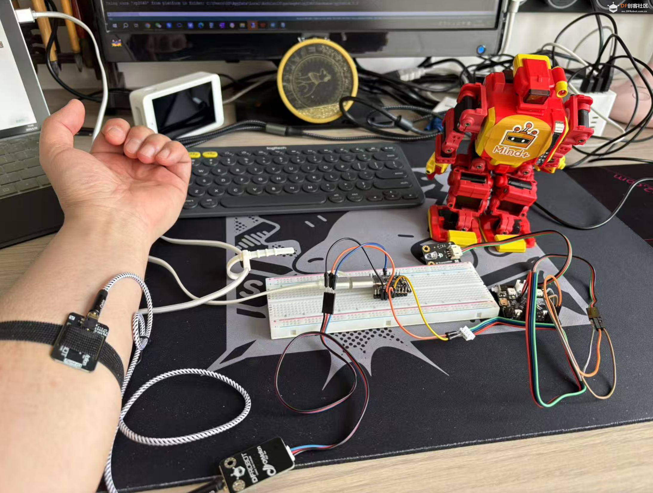 测试视频: |
 创客造
创客造


 沪公网安备31011502402448
© 2013-2026 Comsenz Inc. Powered by Discuz! X3.4 Licensed

 置顶卡
置顶卡 变色卡
变色卡 千斤顶
千斤顶


