|
5079| 0
|
[ESP8266/ESP32] ESP32-S3 AI 智能摄像头模块作为机器人的大脑2 |

|
本帖最后由 Anders项勇 于 2025-5-17 23:11 编辑 【项目背景】 接上个帖子,ESP32-S3 AI已经可以控制机器人了,本项目将尝试用ESP32-S3 AI识别乒乓球,然后让机器人踢球。拍摄乒乓球若干照片,通过ai平台训练,部署在Arduino上,串口得到乒乓球的坐标。根据坐标位置给机器人下达命令,移动到球的合适位置,然后下达踢球命令。 【项目设计】 1.训练ai模型并部署 1.1数据采集 1.1.1arduino IDE中选择File->Examples->ESP32->Camera->CameraWebServer示例。使用下面的代码替换CameraWebServer中的代码(注意:需要填入WIFI账号密码)。打开串口监视器查看ip地址。通过局域网内的设备通过浏览器访问ip,点击start即可看到监控画面。然后对着乒乓球多角度拍摄若干照片save保存进行数据采集。注意:必须确认wifi是2.4g的,5g的ESP32-S3 AI板子不支持。手机热点苹果必须勾选最大兼容性,才能发射2.4g,可能端口监视器半天不显示内容。等一会儿再打开就会显示,如果是5gwifi将一直显示连接中,始终连不上。如果串口没显示,直接在路由器后台看ESP32-S3 AI的ip地址,直接输入ip也能显示摄像头画面。 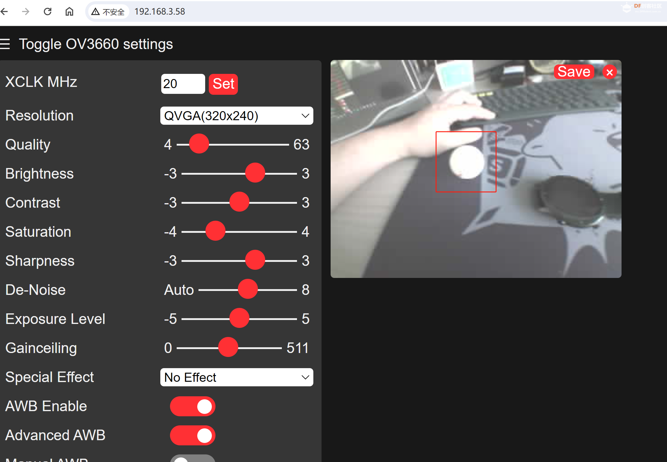  #include "esp_camera.h" #include "esp_camera.h"#include <WiFi.h> // // WARNING!!! PSRAM IC required for UXGA resolution and high JPEG quality // Ensure ESP32 Wrover Module or other board with PSRAM is selected // Partial images will be transmitted if image exceeds buffer size // // You must select partition scheme from the board menu that has at least 3MB APP space. // Face Recognition is DISABLED for ESP32 and ESP32-S2, because it takes up from 15 // seconds to process single frame. Face Detection is ENABLED if PSRAM is enabled as well #define PWDN_GPIO_NUM -1 #define RESET_GPIO_NUM -1 #define XCLK_GPIO_NUM 5 #define Y9_GPIO_NUM 4 #define Y8_GPIO_NUM 6 #define Y7_GPIO_NUM 7 #define Y6_GPIO_NUM 14 #define Y5_GPIO_NUM 17 #define Y4_GPIO_NUM 21 #define Y3_GPIO_NUM 18 #define Y2_GPIO_NUM 16 #define VSYNC_GPIO_NUM 1 #define HREF_GPIO_NUM 2 #define PCLK_GPIO_NUM 15 #define SIOD_GPIO_NUM 8 #define SIOC_GPIO_NUM 9 // =========================== // Enter your WiFi credentials // =========================== const char *ssid = "**********"; const char *password = "**********"; void startCameraServer(); void setupLedFlash(int pin); void setup() { Serial.begin(115200); Serial.setDebugOutput(true); Serial.println(); camera_config_t config; config.ledc_channel = LEDC_CHANNEL_0; config.ledc_timer = LEDC_TIMER_0; config.pin_d0 = Y2_GPIO_NUM; config.pin_d1 = Y3_GPIO_NUM; config.pin_d2 = Y4_GPIO_NUM; config.pin_d3 = Y5_GPIO_NUM; config.pin_d4 = Y6_GPIO_NUM; config.pin_d5 = Y7_GPIO_NUM; config.pin_d6 = Y8_GPIO_NUM; config.pin_d7 = Y9_GPIO_NUM; config.pin_xclk = XCLK_GPIO_NUM; config.pin_pclk = PCLK_GPIO_NUM; config.pin_vsync = VSYNC_GPIO_NUM; config.pin_href = HREF_GPIO_NUM; config.pin_sccb_sda = SIOD_GPIO_NUM; config.pin_sccb_scl = SIOC_GPIO_NUM; config.pin_pwdn = PWDN_GPIO_NUM; config.pin_reset = RESET_GPIO_NUM; config.xclk_freq_hz = 20000000; config.frame_size = FRAMESIZE_UXGA; config.pixel_format = PIXFORMAT_JPEG; // for streaming //config.pixel_format = PIXFORMAT_RGB565; // for face detection/recognition config.grab_mode = CAMERA_GRAB_WHEN_EMPTY; config.fb_location = CAMERA_FB_IN_PSRAM; config.jpeg_quality = 12; config.fb_count = 1; // if PSRAM IC present, init with UXGA resolution and higher JPEG quality // for larger pre-allocated frame buffer. if (config.pixel_format == PIXFORMAT_JPEG) { if (psramFound()) { config.jpeg_quality = 10; config.fb_count = 2; config.grab_mode = CAMERA_GRAB_LATEST; } else { // Limit the frame size when PSRAM is not available config.frame_size = FRAMESIZE_SVGA; config.fb_location = CAMERA_FB_IN_DRAM; } } else { // Best option for face detection/recognition config.frame_size = FRAMESIZE_240X240; #if CONFIG_IDF_TARGET_ESP32S3 config.fb_count = 2; #endif } #if defined(CAMERA_MODEL_ESP_EYE) pinMode(13, INPUT_PULLUP); pinMode(14, INPUT_PULLUP); #endif // camera init esp_err_t err = esp_camera_init(&config); if (err != ESP_OK) { Serial.printf("Camera init failed with error 0x%x", err); return; } sensor_t *s = esp_camera_sensor_get(); // initial sensors are flipped vertically and colors are a bit saturated if (s->id.PID == OV3660_PID) { s->set_vflip(s, 1); // flip it back s->set_brightness(s, 1); // up the brightness just a bit s->set_saturation(s, -2); // lower the saturation } // drop down frame size for higher initial frame rate if (config.pixel_format == PIXFORMAT_JPEG) { s->set_framesize(s, FRAMESIZE_QVGA); } #if defined(CAMERA_MODEL_M5STACK_WIDE) || defined(CAMERA_MODEL_M5STACK_ESP32CAM) s->set_vflip(s, 1); s->set_hmirror(s, 1); #endif #if defined(CAMERA_MODEL_ESP32S3_EYE) s->set_vflip(s, 1); #endif // Setup LED FLash if LED pin is defined in camera_pins.h #if defined(LED_GPIO_NUM) setupLedFlash(LED_GPIO_NUM); #endif WiFi.begin(ssid, password); WiFi.setSleep(false); Serial.print("WiFi connecting"); while (WiFi.status() != WL_CONNECTED) { delay(500); Serial.print("."); } Serial.println(""); Serial.println("WiFi connected"); startCameraServer(); Serial.print("Camera Ready! Use 'http://"); Serial.print(WiFi.localIP()); Serial.println("' to connect"); } void loop() { // Do nothing. Everything is done in another task by the web server delay(10000); } 1.2在EdgeImpulse官网:https://edgeimpulse.com/ 建立项目、上传采集的数据、标记数据、训练模型、部署模型。 建立项目上传采集的数据:  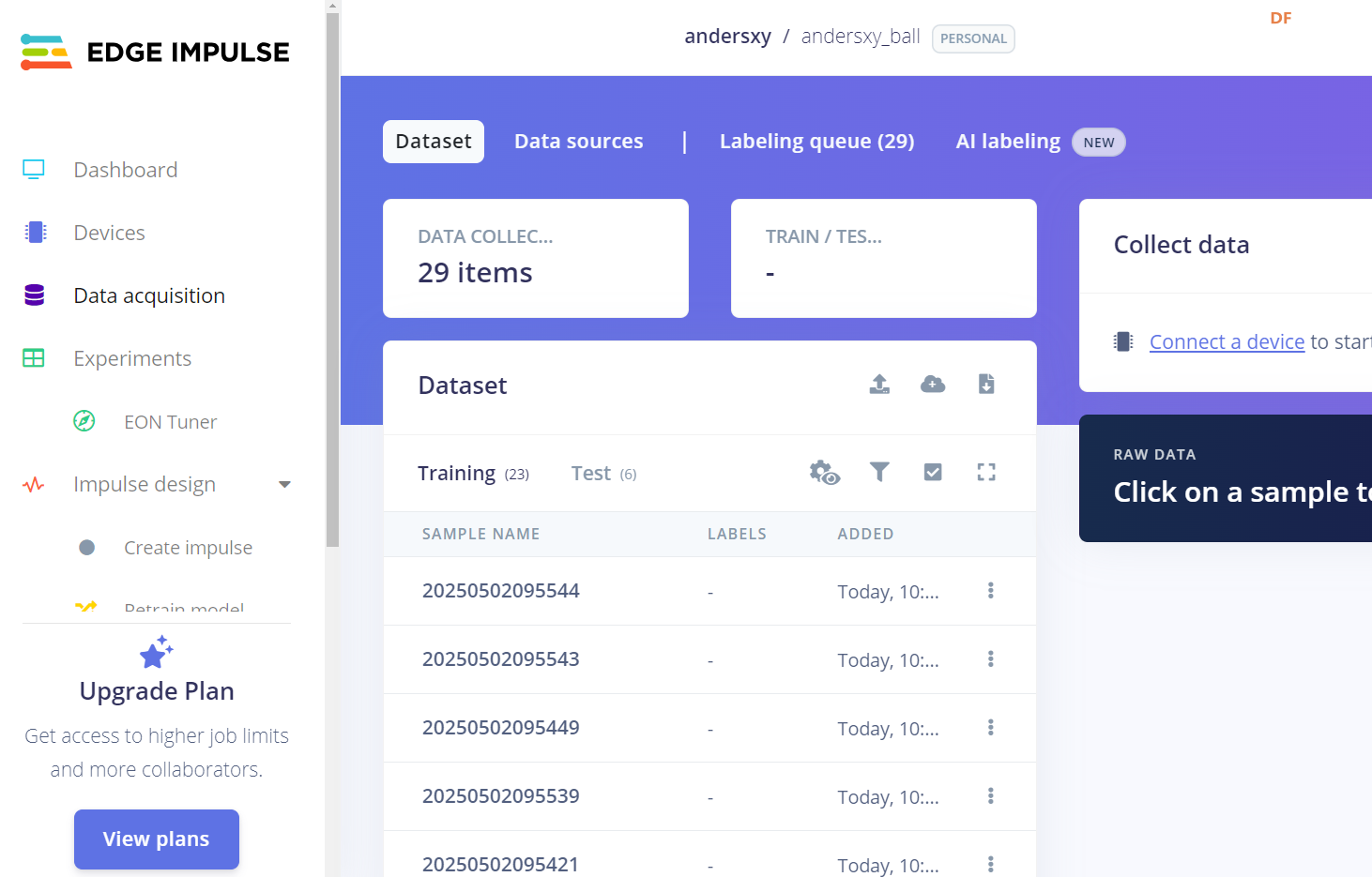 标记数据:每标记一张图片,系统会自动跳到下一张图片,只要调整方框把球套住保存就好了。 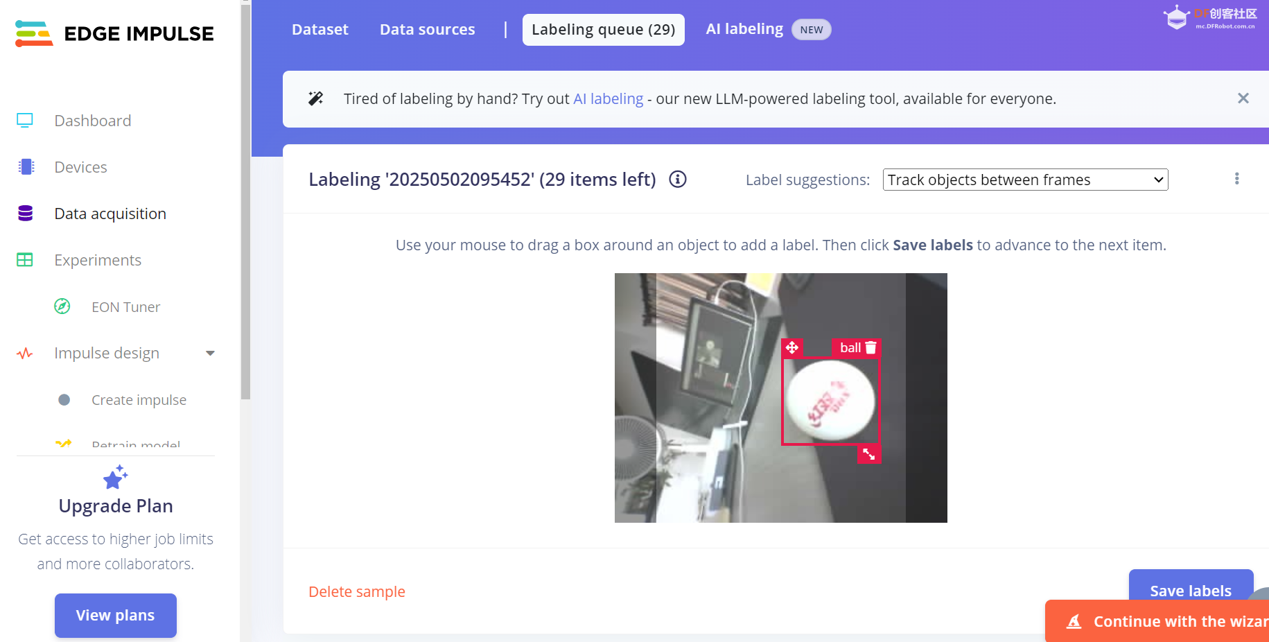 训练模型: 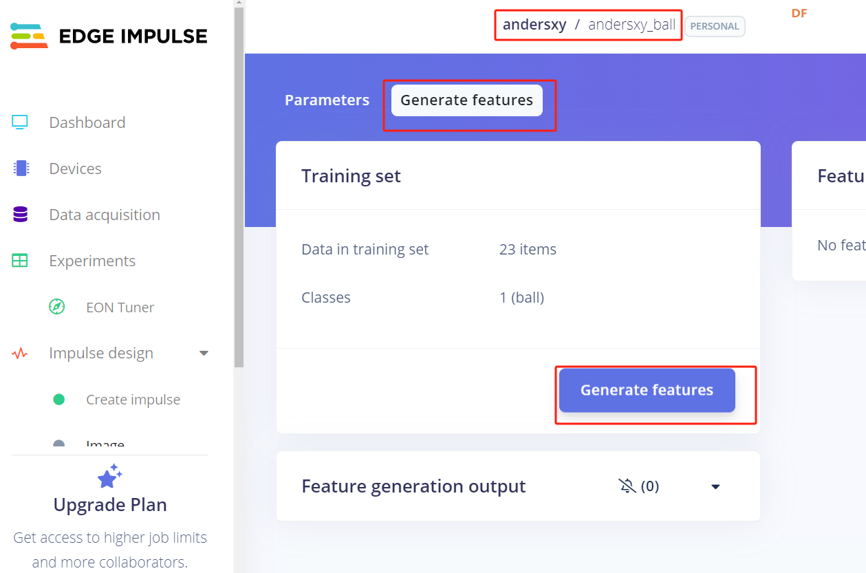 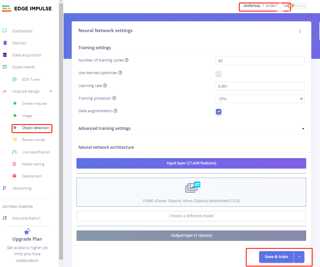 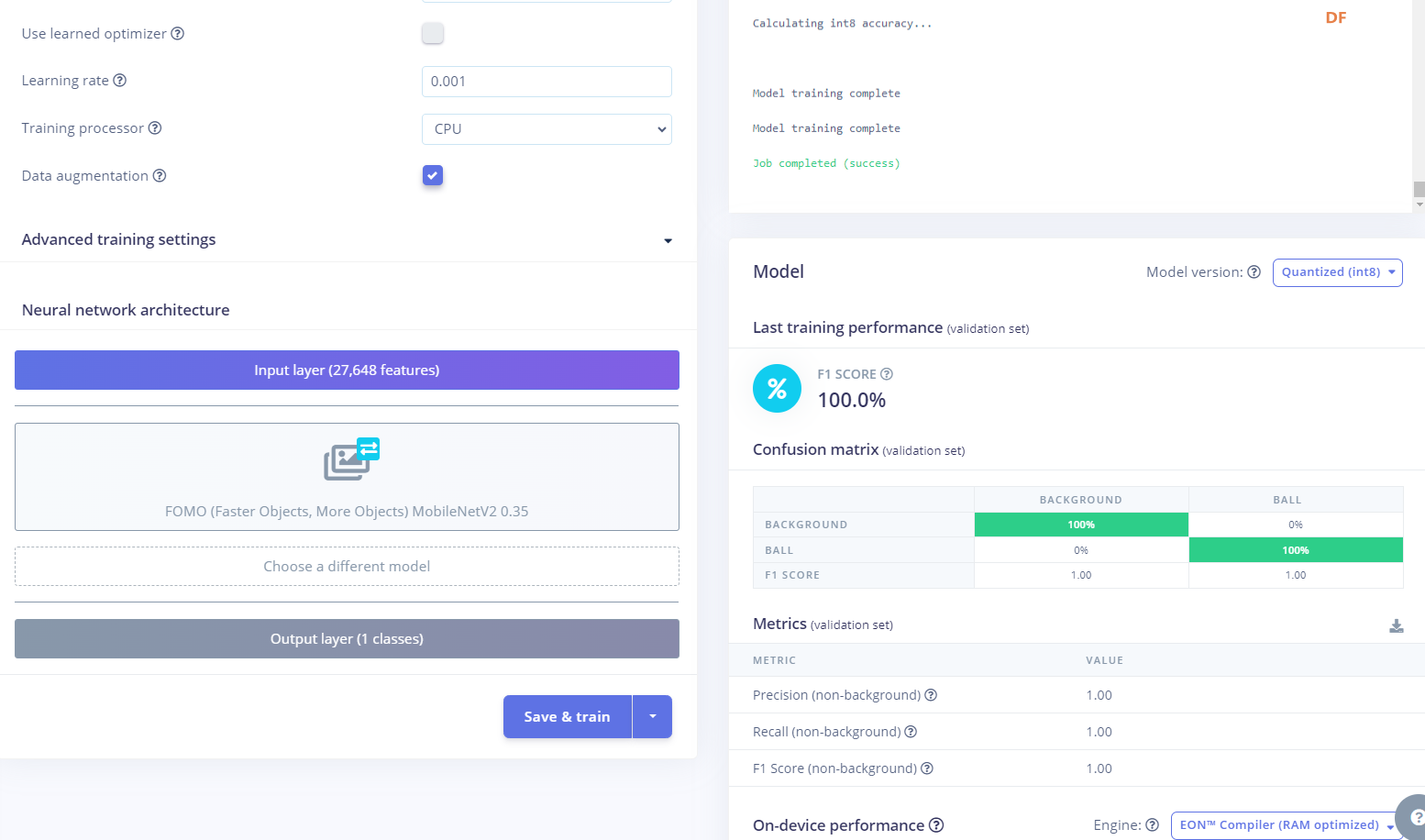 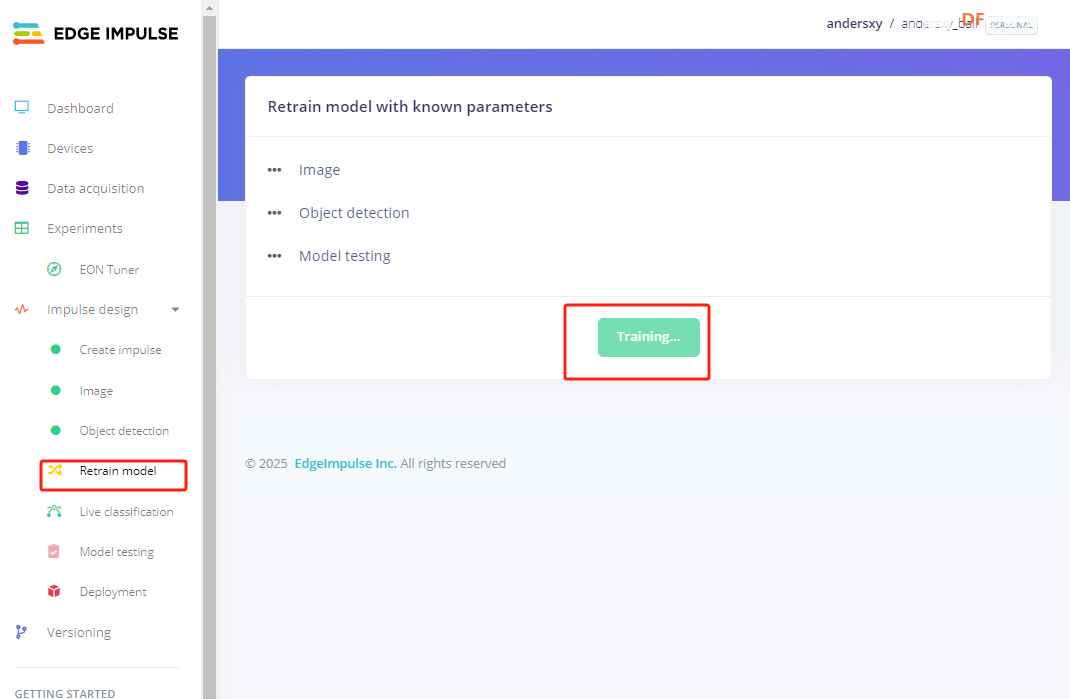 1.3部署模型: 将训练完成的模型库文件解压到"arduino->libraies"中;替换"src\edge-impulse-sdk\tensorflow\lite\micro\kernels"中的"depthwise_conv.cpp"和"conv.cpp"文件;将edge_camera文件夹及其子文件移动到模型库文件的examples中;打开arduino IDE,选择edge_camera示例,将代码中的第一行改为模型库的.h文件,填入WiFi账号密码,然后编译烧录,这个编译要较长时间。打开串口监视器即可看到IP地址和识别结果(识别出ball,置信度,x,y,width,height),访问IP即可看到摄像头画面。编译时这些选项不要搞错,特别是Flash Size、Partition Scheme不要选错,否则会因为编译文件太大而设的空间不够导致编译失败。 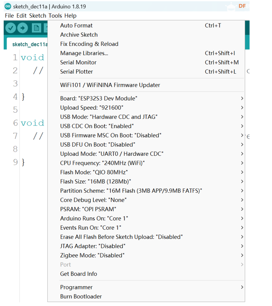 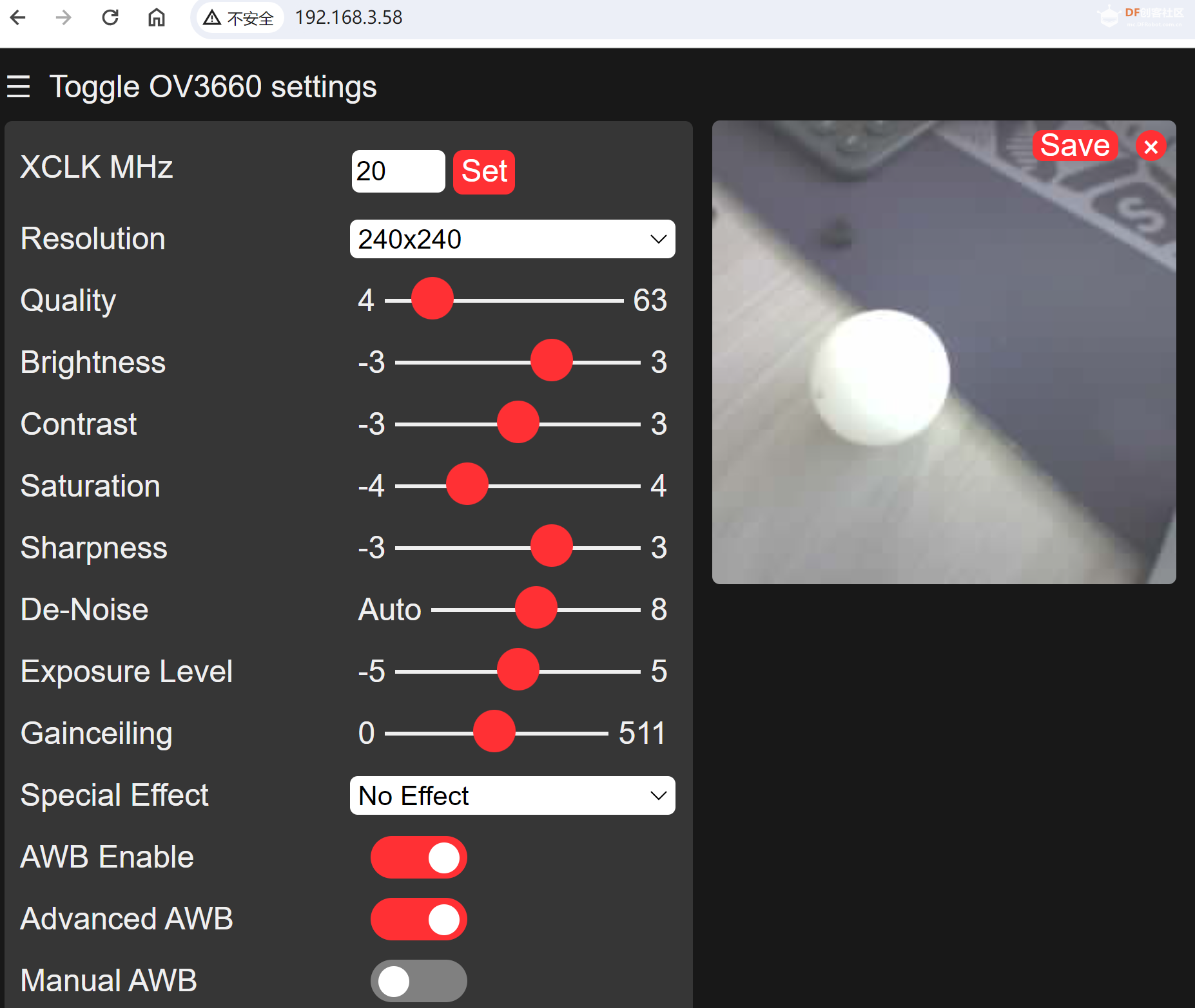 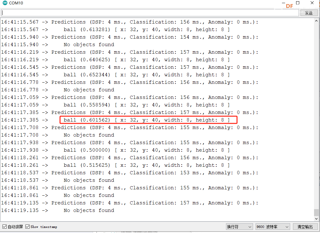 2.改装机器人(把ESP32-S3 AI作为机器人大脑固定放在机器人头上或者胸部)  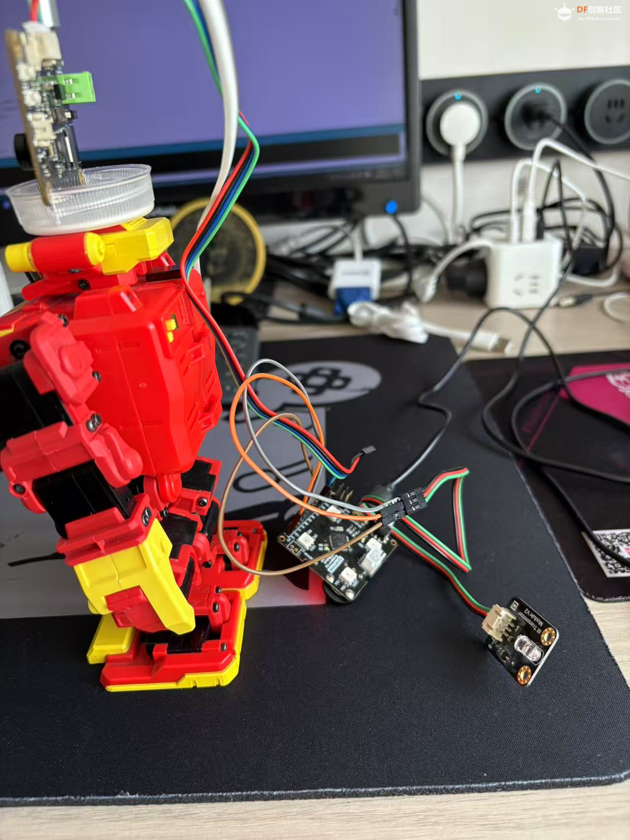 3.改写代码(主要原理是在代码原来输出识别坐标的地方根据识别到的球的位置信息给机器人发送移动和踢球命令通过串口传给sparrow,球处于图像位置的触发值按照测试经验值调整)视频: #include <ball_inferencing.h> #include "edge-impulse-sdk/dsp/image/image.hpp" #include "esp_camera.h" #include <Arduino.h> #define WEB_GRAPHICS #ifdef WEB_GRAPHICS #include <WiFi.h> #include <Wire.h> #include "esp_camera.h" // Enter your WiFi credentials const char* ssid = "***"; const char* password = "***"; void startCameraServer(); void setupLedFlash(int pin); #endif #define PWDN_GPIO_NUM -1 #define RESET_GPIO_NUM -1 #define XCLK_GPIO_NUM 5 #define Y9_GPIO_NUM 4 #define Y8_GPIO_NUM 6 #define Y7_GPIO_NUM 7 #define Y6_GPIO_NUM 14 #define Y5_GPIO_NUM 17 #define Y4_GPIO_NUM 21 #define Y3_GPIO_NUM 18 #define Y2_GPIO_NUM 16 #define VSYNC_GPIO_NUM 1 #define HREF_GPIO_NUM 2 #define PCLK_GPIO_NUM 15 #define SIOD_GPIO_NUM 8 #define SIOC_GPIO_NUM 9 /* Constant defines -------------------------------------------------------- */ #define EI_CAMERA_RAW_FRAME_BUFFER_COLS 240 #define EI_CAMERA_RAW_FRAME_BUFFER_ROWS 240 #define EI_CAMERA_FRAME_BYTE_SIZE 3 /* Private variables ------------------------------------------------------- */ static bool debug_nn = false; // Set this to true to see e.g. features generated from the raw signal static bool is_initialised = false; uint8_t* snapshot_buf; //points to the output of the capture static camera_config_t camera_config = { .pin_pwdn = PWDN_GPIO_NUM, .pin_reset = RESET_GPIO_NUM, .pin_xclk = XCLK_GPIO_NUM, .pin_sscb_sda = SIOD_GPIO_NUM, .pin_sscb_scl = SIOC_GPIO_NUM, //.pin_sccb_sda = -1, //.pin_sccb_scl = -1, .pin_d7 = Y9_GPIO_NUM, .pin_d6 = Y8_GPIO_NUM, .pin_d5 = Y7_GPIO_NUM, .pin_d4 = Y6_GPIO_NUM, .pin_d3 = Y5_GPIO_NUM, .pin_d2 = Y4_GPIO_NUM, .pin_d1 = Y3_GPIO_NUM, .pin_d0 = Y2_GPIO_NUM, .pin_vsync = VSYNC_GPIO_NUM, .pin_href = HREF_GPIO_NUM, .pin_pclk = PCLK_GPIO_NUM, //XCLK 20MHz or 10MHz for OV2640 double FPS (Experimental) .xclk_freq_hz = 20000000, .ledc_timer = LEDC_TIMER_0, .ledc_channel = LEDC_CHANNEL_0, .pixel_format = PIXFORMAT_JPEG, //YUV422,GRAYSCALE,RGB565,JPEG .frame_size = FRAMESIZE_240X240, //QQVGA-UXGA Do not use sizes above QVGA when not JPEG .jpeg_quality = 12, //0-63 lower number means higher quality .fb_count = 2, //if more than one, i2s runs in continuous mode. Use only with JPEG .fb_location = CAMERA_FB_IN_PSRAM, .grab_mode = CAMERA_GRAB_WHEN_EMPTY, .sccb_i2c_port = 0, }; /* Function definitions ------------------------------------------------------- */ bool ei_camera_init(void); void ei_camera_deinit(void); bool ei_camera_capture(uint32_t img_width, uint32_t img_height, uint8_t* out_buf); /** * @brief Arduino setup function */ void setup() { // put your setup code here, to run once: Serial.begin(115200); Serial.println("Edge Impulse Inferencing Demo"); Serial1.begin(115200); if (ei_camera_init() == false) { Serial.println("Failed to initialize Camera!\r\n"); } else { Serial.println("Camera initialized\r\n"); } #ifdef WEB_GRAPHICS /**************** WiFi init ****************/ WiFi.begin(ssid, password); WiFi.setSleep(false); while (WiFi.status() != WL_CONNECTED) { delay(500); Serial.print("."); } Serial.println("\nWiFi connected"); startCameraServer(); Serial.print("Camera Ready! Use 'http://"); Serial.print(WiFi.localIP()); Serial.println("' to connect"); delay(1000); #endif Serial.println("\nStarting continious inference in 2 seconds...\n"); ei_sleep(2000); } /** * @brief Get data and run inferencing * * @param[in] debug Get debug info if true */ void loop() { // instead of wait_ms, we'll wait on the signal, this allows threads to cancel us... if (ei_sleep(5) != EI_IMPULSE_OK) { return; } snapshot_buf = (uint8_t*)malloc(EI_CAMERA_RAW_FRAME_BUFFER_COLS * EI_CAMERA_RAW_FRAME_BUFFER_ROWS * EI_CAMERA_FRAME_BYTE_SIZE); // check if allocation was successful if (snapshot_buf == nullptr) { ei_printf("ERR: Failed to allocate snapshot buffer!\n"); free(snapshot_buf); return; } ei::signal_t signal; signal.total_length = EI_CLASSIFIER_INPUT_WIDTH * EI_CLASSIFIER_INPUT_HEIGHT; signal.get_data = &ei_camera_get_data; if (ei_camera_capture((size_t)EI_CLASSIFIER_INPUT_WIDTH, (size_t)EI_CLASSIFIER_INPUT_HEIGHT, snapshot_buf) == false) { ei_printf("Failed to capture image\r\n"); free(snapshot_buf); return; } // Run the classifier ei_impulse_result_t result = { 0 }; EI_IMPULSE_ERROR err = run_classifier(&signal, &result, debug_nn); if (err != EI_IMPULSE_OK) { ei_printf("ERR: Failed to run classifier (%d)\n", err); free(snapshot_buf); return; } // print the predictions ei_printf("Predictions (DSP: %d ms., Classification: %d ms., Anomaly: %d ms.): \n", result.timing.dsp, result.timing.classification, result.timing.anomaly); #if EI_CLASSIFIER_OBJECT_DETECTION == 1 bool bb_found = result.bounding_boxes[0].value > 0; for (size_t ix = 0; ix < result.bounding_boxes_count; ix++) { auto bb = result.bounding_boxes[ix]; if (bb.value == 0) { continue; } ei_printf(" %s (%f) [ x: %u, y: %u, width: %u, height: %u ]\n", bb.label, bb.value, bb.x, bb.y, bb.width, bb.height); if (bb.x<40) { // 移动位置踢球 Serial1.print("a"); } if (bb.y<40) { Serial1.print("w"); } if (bb.x>40 && bb.y>40) { Serial1.print("p"); } } if (!bb_found) { ei_printf(" No objects found\n"); } #else for (size_t ix = 0; ix < EI_CLASSIFIER_LABEL_COUNT; ix++) { ei_printf(" %s: %.5f\n", result.classification[ix].label, result.classification[ix].value); } #endif #if EI_CLASSIFIER_HAS_ANOMALY == 1 ei_printf(" anomaly score: %.3f\n", result.anomaly); #endif free(snapshot_buf); } /** * @brief Setup image sensor & start streaming * * @retval false if initialisation failed */ bool ei_camera_init(void) { if (is_initialised) return true; #if defined(CAMERA_MODEL_ESP_EYE) pinMode(13, INPUT_PULLUP); pinMode(14, INPUT_PULLUP); #endif //Wire.begin(); // 初始化默认的i2c接口, 内部初始化会改变i2c总线 //initialize the camera esp_err_t err = esp_camera_init(&camera_config); if (err != ESP_OK) { Serial.printf("Camera init failed with error 0x%x\n", err); return false; } sensor_t* s = esp_camera_sensor_get(); // initial sensors are flipped vertically and colors are a bit saturated if (s->id.PID == OV3660_PID) { s->set_vflip(s, 1); // flip it back s->set_brightness(s, 1); // up the brightness just a bit s->set_saturation(s, 0); // lower the saturation } // #if defined(CAMERA_MODEL_M5STACK_WIDE) // s->set_vflip(s, 1); // s->set_hmirror(s, 1); // #else // s->set_vflip(s, 1); // s->set_hmirror(s, 1); // s->set_awb_gain(s, 1); // #endif is_initialised = true; // Setup LED FLash if LED pin is defined in camera_pins.h #if defined(LED_GPIO_NUM) setupLedFlash(LED_GPIO_NUM); #endif return true; } /** * @brief Stop streaming of sensor data */ void ei_camera_deinit(void) { //deinitialize the camera esp_err_t err = esp_camera_deinit(); if (err != ESP_OK) { ei_printf("Camera deinit failed\n"); return; } is_initialised = false; return; } /** * @brief Capture, rescale and crop image * * @param[in] img_width width of output image * @param[in] img_height height of output image * @param[in] out_buf pointer to store output image, NULL may be used * if ei_camera_frame_buffer is to be used for capture and resize/cropping. * * @retval false if not initialised, image captured, rescaled or cropped failed * */ bool ei_camera_capture(uint32_t img_width, uint32_t img_height, uint8_t* out_buf) { bool do_resize = false; if (!is_initialised) { ei_printf("ERR: Camera is not initialized\r\n"); return false; } camera_fb_t* fb = esp_camera_fb_get(); if (!fb) { ei_printf("Camera capture failed\n"); return false; } bool converted = fmt2rgb888(fb->buf, fb->len, PIXFORMAT_JPEG, snapshot_buf); esp_camera_fb_return(fb); if (!converted) { ei_printf("Conversion failed\n"); return false; } if ((img_width != EI_CAMERA_RAW_FRAME_BUFFER_COLS) || (img_height != EI_CAMERA_RAW_FRAME_BUFFER_ROWS)) { do_resize = true; } if (do_resize) { ei::image::processing::crop_and_interpolate_rgb888( out_buf, EI_CAMERA_RAW_FRAME_BUFFER_COLS, EI_CAMERA_RAW_FRAME_BUFFER_ROWS, out_buf, img_width, img_height); } return true; } static int ei_camera_get_data(size_t offset, size_t length, float* out_ptr) { // we already have a RGB888 buffer, so recalculate offset into pixel index size_t pixel_ix = offset * 3; size_t pixels_left = length; size_t out_ptr_ix = 0; while (pixels_left != 0) { // Swap BGR to RGB here // due to https://github.com/espressif/esp32-camera/issues/379 out_ptr[out_ptr_ix] = (snapshot_buf[pixel_ix + 2] << 16) + (snapshot_buf[pixel_ix + 1] << 8) + snapshot_buf[pixel_ix]; // go to the next pixel out_ptr_ix++; pixel_ix += 3; pixels_left--; } // and done! return 0; } #if !defined(EI_CLASSIFIER_SENSOR) || EI_CLASSIFIER_SENSOR != EI_CLASSIFIER_SENSOR_CAMERA #error "Invalid model for current sensor" #endif |
 创客造
创客造


 沪公网安备31011502402448
© 2013-2026 Comsenz Inc. Powered by Discuz! X3.4 Licensed

 置顶卡
置顶卡 变色卡
变色卡 千斤顶
千斤顶


