|
1233| 0
|
[ESP8266/ESP32] ESP32-C5 测试1--连接屏幕 |
|
本帖最后由 Anders项勇 于 2025-10-20 23:48 编辑 这次幸运抽取到试用ESP32-C5,先测试其基本功能: 1.Arduino环境: Arduino先安装ESP32-C5板子,首先项添加https://github.com/espressif/ard ... 2_dev_index_cn.json 开发板管理输入esp32,选择3.3.0-alpha1-cn 2.安装透明屏幕库 屏幕使用Fermion: 1.51”OLED 透明屏幕,先下载库的zip文件,因为在库管理器搜索U8g2库安装的并不对。zip库下载地址:https://gitee.com/dfrobot/U8g2_A ... /archive/master.zip 下载后到项目--导入库--添加zip库文件导入下载的库文件 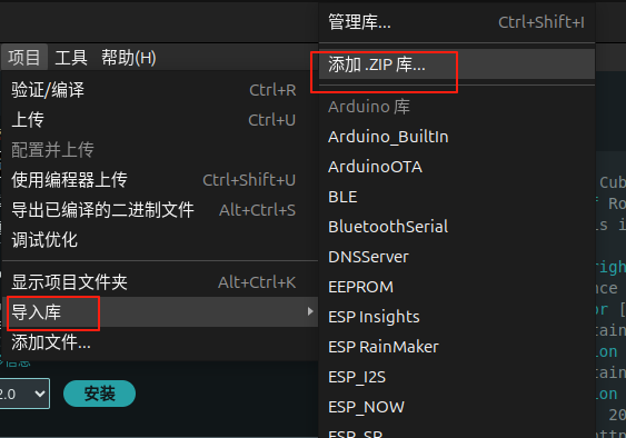 用转接板连接开发板和屏幕 3.端口权限: 由于这次是使用一台ubuntu电脑上的arduino编写代码,所以要注意端口权限,否则无法烧录代码。 端口权限开放有两种在终端运行的方法: 1)添加用户到dialout组(需注销重新登录)sudo usermod -aG dialout $USER 2)临时权限方案 sudo chmod 666 /dev/ttyACM0 ttyACM0是我当前的端口名称 4.代码测试: #include <Arduino.h> #include <U8g2lib.h> #include <SPI.h> #if defined ARDUINO_SAM_ZERO #define OLED_DC 7 #define OLED_CS 5 #define OLED_RST 6 /*ESP32 */ #elif defined(ESP32) #define OLED_DC D2 #define OLED_CS D6 #define OLED_RST D3 /*ESP8266*/ #elif defined(ESP8266) #define OLED_DC D4 #define OLED_CS D6 #define OLED_RST D5 /*AVR series board*/ #else #define OLED_DC 2 #define OLED_CS 3 #define OLED_RST 4 #endif U8G2_SSD1309_128X64_NONAME2_1_4W_HW_SPI u8g2(/* rotation=*/U8G2_R0, /* cs=*/ OLED_CS, /* dc=*/ OLED_DC,/* reset=*/OLED_RST); //2D array: The coordinates of all vertices of the tetrahesome are stored double tetrahedron[4][3] = {{0,20,-20},{-20,-20,-20},{20,-20,-20},{0,0,20}}; void setup(void) { u8g2.begin(); } void loop(void) { /* * firstPage will change the current page number position to 0 * When modifications are between firstpage and nextPage, they will be re-rendered at each time. * This method consumes less ram space than sendBuffer */ u8g2.firstPage(); do { //Connect the corresponding points inside the tetrahethal together u8g2.drawLine(OxyzToOu(tetrahedron[0][0], tetrahedron[0][2]), OxyzToOv(tetrahedron[0][1], tetrahedron[0][2]), OxyzToOu(tetrahedron[1][0], tetrahedron[1][2]), OxyzToOv(tetrahedron[1][1], tetrahedron[1][2])); u8g2.drawLine(OxyzToOu(tetrahedron[1][0], tetrahedron[1][2]), OxyzToOv(tetrahedron[1][1], tetrahedron[1][2]), OxyzToOu(tetrahedron[2][0], tetrahedron[2][2]), OxyzToOv(tetrahedron[2][1], tetrahedron[2][2])); u8g2.drawLine(OxyzToOu(tetrahedron[0][0], tetrahedron[0][2]), OxyzToOv(tetrahedron[0][1], tetrahedron[0][2]), OxyzToOu(tetrahedron[2][0], tetrahedron[2][2]), OxyzToOv(tetrahedron[2][1], tetrahedron[2][2])); u8g2.drawLine(OxyzToOu(tetrahedron[0][0], tetrahedron[0][2]), OxyzToOv(tetrahedron[0][1], tetrahedron[0][2]), OxyzToOu(tetrahedron[3][0], tetrahedron[3][2]), OxyzToOv(tetrahedron[3][1], tetrahedron[3][2])); u8g2.drawLine(OxyzToOu(tetrahedron[1][0], tetrahedron[1][2]), OxyzToOv(tetrahedron[1][1], tetrahedron[1][2]), OxyzToOu(tetrahedron[3][0], tetrahedron[3][2]), OxyzToOv(tetrahedron[3][1], tetrahedron[3][2])); u8g2.drawLine(OxyzToOu(tetrahedron[2][0], tetrahedron[2][2]), OxyzToOv(tetrahedron[2][1], tetrahedron[2][2]), OxyzToOu(tetrahedron[3][0], tetrahedron[3][2]), OxyzToOv(tetrahedron[3][1], tetrahedron[3][2])); // Rotate 0.1° rotate(0.1); } while ( u8g2.nextPage() ); //delay(50); } /*! * @brief Convert xz in the three-dimensional coordinate system Oxyz * into the u coordinate inside the two-dimensional coordinate system Ouv * @param x in Oxyz * @param z in Oxyz * @return u in Ouv */ int OxyzToOu(double x,double z){ return (int)((x + 64) - z*0.35); } /*! * @brief Convert the yz in the three-dimensional coordinate system Oxyz into the v coordinate inside * the two-dimensional coordinate system Ouv * @param y in Oxyz * @param z in Oxyz * @return v in Ouv */ int OxyzToOv(double y,double z){ return (int)((y + 26) - z*0.35); } /*! * @brief Rotate the coordinates of all points of the entire 3D graphic around the Z axis * @param angle represents the angle to rotate * * z rotation (z unchanged) x3 = x2 * cosb - y1 * sinb y3 = y1 * cosb + x2 * sinb z3 = z2 */ void rotate(double angle) { double rad, cosa, sina, Xn, Yn; rad = angle * PI / 180; cosa = cos(rad); sina = sin(rad); for (int i = 0; i < 4; i++) { Xn = (tetrahedron[0] * cosa) - (tetrahedron[1] * sina); Yn = (tetrahedron[0] * sina) + (tetrahedron[1] * cosa); //Store converted coordinates into an array of coordinates //Because it rotates around the Z-axis, the coordinates of the point z-axis remain unchanged tetrahedron[0] = Xn; tetrahedron[1] = Yn; } } 但屏幕并不显示,不知道是端口设置错误还是不支持这个屏幕 |
 创客造
创客造


 沪公网安备31011502402448
© 2013-2026 Comsenz Inc. Powered by Discuz! X3.4 Licensed

 置顶卡
置顶卡 变色卡
变色卡 千斤顶
千斤顶


