首次使用
Ar duino环境配置
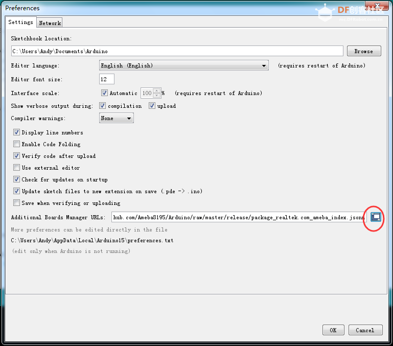
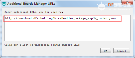
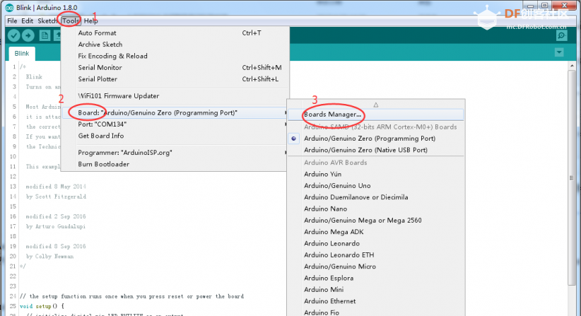
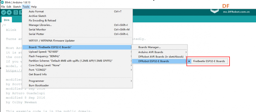
当您首次使用FireBeetle主控,您需要了解以下步骤
- 添加IDE中的json链接
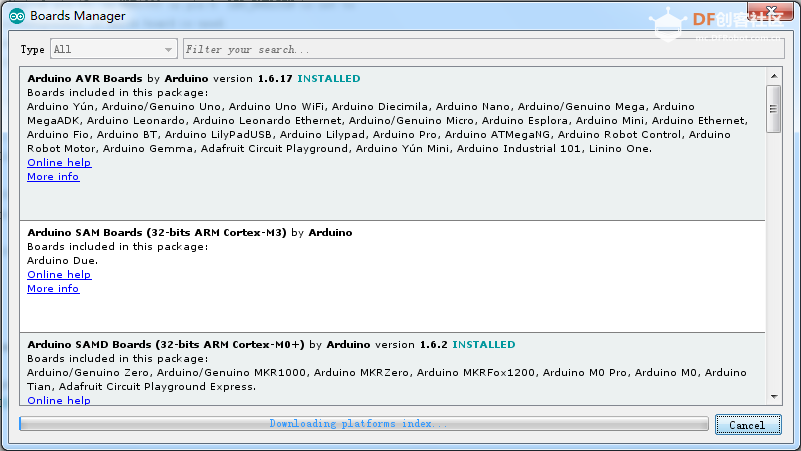
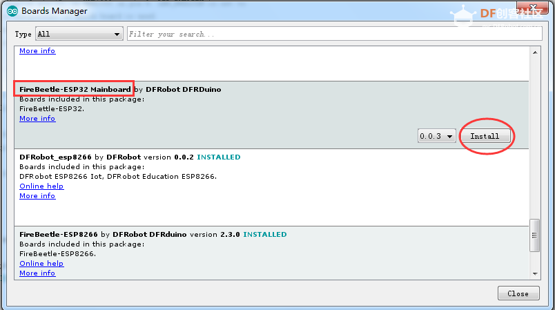
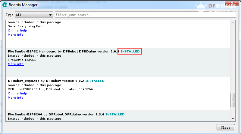
- 下载主控的核心
- 选择开发板以及串口
- 打开示例程序并烧录
- 了解串口监视器
Blink
如果这是您第一次接触arduino,此例程将是您的第一个程序
烧录此程序您将看到LED规律闪烁
FireBeetle Board-ESP32默认Blink灯连接到D9/2
    // the setup function runs once when you press reset or power the board
    void setup() {
      // initialize digital pin LED_BUILTIN as an output.
      pinMode(LED_BUILTIN, OUTPUT);
    }

    // the loop function runs over and over again forever
    void loop() {
      digitalWrite(LED_BUILTIN, HIGH);   // turn the LED on (HIGH is the voltage level)
      delay(1000);                       // wait for a second
      digitalWrite(LED_BUILTIN, LOW);    // turn the LED off by making the voltage LOW
      delay(1000);                       // wait for a second
    }
- 将以上程序粘贴到程序框中
- 点击箭头等待程序编译并烧录至开发板
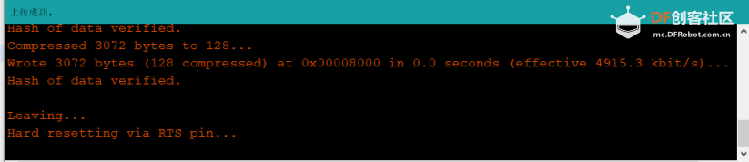
烧录成功
蓝牙基础示例
ESP32具有蓝牙功能,此例程将示范使用两块FireBeetle ESP32-E进行蓝牙透传。
通过其中一块ESP32向另一块ESP32发送数据,是使用蓝牙无线通信的最基本模型。
//This example code is in the Public Domain (or CC0 licensed, at your option.)
//By Victor Tchistiak - 2019
//
//This example demostrates master mode bluetooth connection and pin
//it creates a bridge between Serial and Classical Bluetooth (SPP)
//this is an extention of the SerialToSerialBT example by Evandro Copercini - 2018
//

#include "BluetoothSerial.h"

BluetoothSerial SerialBT;

String MACadd = "AA:BB:CC:11:22:33";
uint8_t address[6]  = {0xAA, 0xBB, 0xCC, 0x11, 0x22, 0x33};
//uint8_t address[6]  = {0x00, 0x1D, 0xA5, 0x02, 0xC3, 0x22};
String name = "ESP32test";
char *pin = "1234"; //<- standard pin would be provided by default
bool connected;

void setup() {
  Serial.begin(115200);
  //SerialBT.setPin(pin);
  SerialBT.begin("ESP32master", true);
  //SerialBT.setPin(pin);
  Serial.println("The device started in master mode, make sure remote BT device is on!");

  // connect(address) is fast (upto 10 secs max), connect(name) is slow (upto 30 secs max) as it needs
  // to resolve name to address first, but it allows to connect to different devices with the same name.
  // Set CoreDebugLevel to Info to view devices bluetooth address and device names
  connected = SerialBT.connect(name);
  //connected = SerialBT.connect(address);

  if(connected) {
    Serial.println("Connected Succesfully!");
  } else {
    while(!SerialBT.connected(10000)) {
      Serial.println("Failed to connect. Make sure remote device is available and in range, then restart app.");
    }
  }
  // disconnect() may take upto 10 secs max
  if (SerialBT.disconnect()) {
    Serial.println("Disconnected Succesfully!");
  }
  // this would reconnect to the name(will use address, if resolved) or address used with connect(name/address).
  SerialBT.connect();
}

void loop() {
  if (Serial.available()) {
    SerialBT.write(Serial.read());
  }
  if (SerialBT.available()) {
    Serial.write(SerialBT.read());
  }
  delay(20);
}
//This example code is in the Public Domain (or CC0 licensed, at your option.)
//By Evandro Copercini - 2018
//
//This example creates a bridge between Serial and Classical Bluetooth (SPP)
//and also demonstrate that SerialBT have the same functionalities of a normal Serial

#include "BluetoothSerial.h"

#if !defined(CONFIG_BT_ENABLED) || !defined(CONFIG_BLUEDROID_ENABLED)
#error Bluetooth is not enabled! Please run `make menuconfig` to and enable it
#endif

BluetoothSerial SerialBT;

void setup() {
  Serial.begin(115200);
  SerialBT.begin("ESP32test"); //Bluetooth device name
  Serial.println("The device started, now you can pair it with bluetooth!");
}

void loop() {
  if (Serial.available()) {
    SerialBT.write(Serial.read());
  }
  if (SerialBT.available()) {
    Serial.write(SerialBT.read());
  }
  delay(20);
}
结果
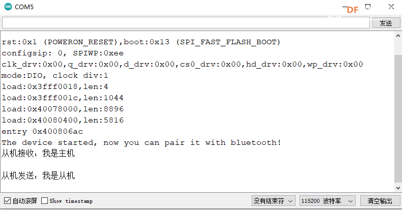
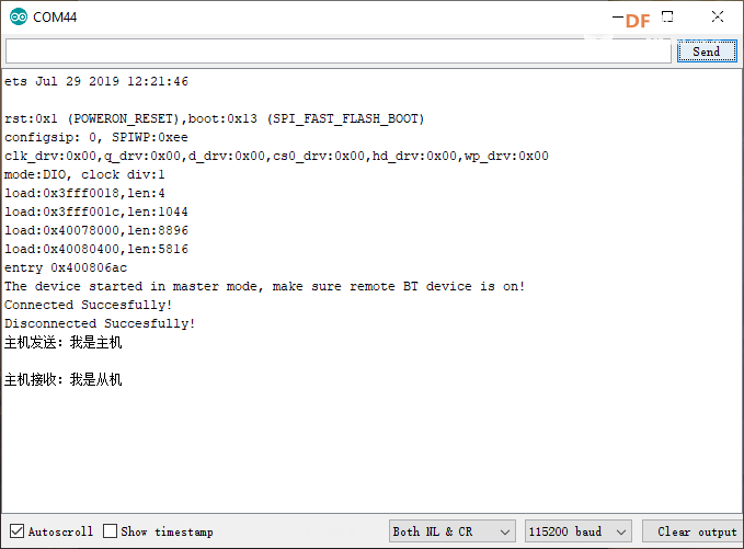
通过主机串口发送:“我是主机”
从机串口显示“从机接收:我是主机”
通过从机串口发送:“我是从机”
主机串口显示“主机接收:我是从机”
成员函数
- SerialBT.begin()
说明:初始化蓝牙模块。
- SerialBT.disconnect()
说明:断开设备连接
返回值:ture/false
- SerialBT.connect()
说明:连接设备
返回值:ture/false
- SerialBT.available()
说明:判断蓝牙是否接收到数据
- SerialBT.read()
说明:读取蓝牙接收的信息
返回值:string
- SerialBT.write()
说明:通过蓝牙发送信息
WIFI基础示例
ESP32具有WIFI功能,以下示例使用ESP32创建了一个wifi服务器,使用客户端连接到该服务器,遥控LED的亮灭
/*
  WiFiAccessPoint.ino 创建了一个wifi热点并提供了一个web服务

  Steps:
  1. 连接到这个wifi "yourAp"
  2. 访问 http://192.168.4.1/H 来开灯或者访问http://192.168.4.1/L 来关灯
     OR
     Run raw TCP "GET /H" and "GET /L" on PuTTY terminal with 192.168.4.1 as IP address and 80 as port
*/

#include <WiFi.h>
#include <WiFiClient.h>
#include <WiFiAP.h>

// 设置你的wifi与密码
const char *ssid = "esp32";
const char *password = "";

WiFiServer server(80);

void setup() {
  pinMode(LED_BUILTIN, OUTPUT);//将LED引脚设置为输出模式
  Serial.begin(115200);
  Serial.println();
  Serial.println("Configuring access point...");

  // 配置wifi以及获取IP地址.
  WiFi.softAP(ssid, password);
  IPAddress myIP = WiFi.softAPIP();
  Serial.print("AP IP address: ");
  Serial.println(myIP);
  server.begin();

  Serial.println("Server started");
}

void loop() {
  WiFiClient client = server.available();   // listen for incoming clients

  if (client) {                             // if you get a client,
    Serial.println("New Client.");           // print a message out the serial port
    String currentLine = "";                // make a String to hold incoming data from the client
    while (client.connected()) {            // loop while the client's connected
      if (client.available()) {             // if there's bytes to read from the client,
        char c = client.read();             // read a byte, then
        Serial.write(c);                    // print it out the serial monitor
        if (c == '\n') {                    // if the byte is a newline character

          // if the current line is blank, you got two newline characters in a row.
          // that's the end of the client HTTP request, so send a response:
          if (currentLine.length() == 0) {
            // HTTP headers always start with a response code (e.g. HTTP/1.1 200 OK)
            // and a content-type so the client knows what's coming, then a blank line:
            client.println("HTTP/1.1 200 OK");
            client.println("Content-type:text/html");
            client.println();

            // the content of the HTTP response follows the header:
            client.print("Click <a href=\"/H\">here</a> to turn ON the LED.<br>");
            client.print("Click <a href=\"/L\">here</a> to turn OFF the LED.<br>");

            // The HTTP response ends with another blank line:
            client.println();
            // break out of the while loop:
            break;
          } else {    // if you got a newline, then clear currentLine:
            currentLine = "";
          }
        } else if (c != '\r') {  // if you got anything else but a carriage return character,
          currentLine += c;      // add it to the end of the currentLine
        }

        // Check to see if the client request was "GET /H" or "GET /L":
        if (currentLine.endsWith("GET /H")) {
          digitalWrite(LED_BUILTIN, HIGH);               // GET /H turns the LED on
        }
        if (currentLine.endsWith("GET /L")) {
          digitalWrite(LED_BUILTIN, LOW);                // GET /L turns the LED off
        }
      }
    }
    // close the connection:
    client.stop();
    Serial.println("Client Disconnected.");
  }
}
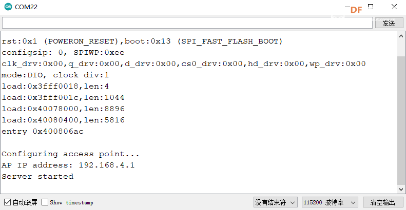
结果
使用手机连接该wifi,通过浏览器访问192.168.4.1,如图所示显示ip地址为192.168.4.1,服务已开启
使用浏览器访问该ip地址得到如下图所示

尝试分别点击链接控制LED吧
成员函数
- begin()
说明:wifi模块初始化
- softAP(ssid,password)
说明:将WiFi配置为AP模式,并设置名称以及密码
参数:
- ssid:AP模式的wifi名字
- password:ap模式的wifi密码
- disconnect()
说明:断开客户端连接
- connect()
说明:客户端连接
- read()
说明:
读取wifi接受到的数据
- write()
说明:通过wifi发送数据
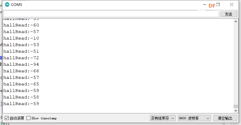
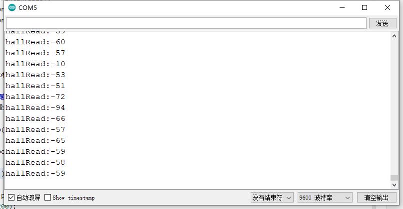
霍尔传感器
ESP32自带霍尔传感器 , 当有磁场靠近时,会显示正负值
void setup()
{
  Serial.begin(9600);
}
void loop()
{
   Serial.printf("hallRead:%d\n",hallRead());
   delay(200);
}
结果
!([img]https://img.dfrobot.com.cn/wiki/none/f02f8d73dc50abd917e6617163b9e528.jpg)
成员函数
- hallRead()
说明:模组内部霍尔传感器读取值
返回值:返回0-255整数,N极为正值,S极为负值,当磁场越强绝对值越大
电容按键
ESP32提供了电容触摸传感器的功能, 共有T0,T2~T9 共 9个touch传感器可用.分别对应引脚4、2、15、13、12、14、27、33、32. 无需设置PinMode,touchRead()返回值为0~255. 触摸强度越大,返回值越小。 烧录此例程,将使用4/D12引脚作为触摸按键,并通过串口监视器返回触摸值
void setup()
{
  Serial.begin(9600);
}

void loop()
{
   Serial.printf("touch:%d\n",touchRead(4));
}
结果
成员函数
-
TouchRead(pin)
说明
:无需设置PinMode
参数
:
- pin:需要调用的触摸传感器引脚
- *返回值** :返回值为0~255. 触摸强度越大,返回值越小。
GDI显示接口
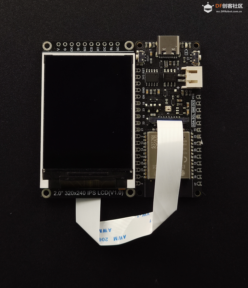
此接口为DFRbot专用GDI显示屏接口,使用18pin-FPC线连接,单线材连接屏幕,为您提供最简捷的屏幕使用方式。
以下是GDI接口使用的引脚列表
| FPC PINS |
FireBeetle M0 PINS |
Description |
| VCC |
3V3 |
3.3V |
| BLK(PWM调光) |
12/D13 |
背光 |
| GND |
GND |
GND |
| SCLK |
18/SCK |
SPI时钟 |
| MOSI |
23/MOSI |
主机输出,从机输入 |
| MISO |
19/MISO |
主机输入,从机输出 |
| DC |
25/D2 |
数据/命令 |
| RES |
26/D3 |
复位 |
| CS |
14/D6 |
TFT片选 |
| SDCS |
13/D7 |
SD卡片选 |
| FCS |
0/D5 |
字库 |
| TCS |
4/D12 |
触摸 |
| SCL |
22/SCL |
I2C时钟 |
| SDA |
21/SDA |
I2C数据 |
| INT |
16/D11 |
INT |
| BUSY-TE |
17/D10 |
防撕裂引脚 |
| X1 |
NC |
自定义引脚1 |
| X2 |
NC |
自定义引脚2 |
使用FPC链接屏幕时根据GDL demo配置所需对应的引脚号即可,通常只需要根据不同主控配置三个引脚
支持GDI的显示屏:
/*ESP32 and ESP8266*/
#elif defined(ESP32) || defined(ESP8266)
#define TFT_DC  25
#define TFT_CS  14
#define TFT_RST 26
Copy
具体使用方式请参考,GDL显示屏wiki:https://wiki.dfrobot.com.cn/_SKU_DFR0664_2.0_240x320_LCD
NOTE: 请不要重复使用相关引脚
RGB_LED
FastLED是一款功能强大却简单易用的可以控制WS2812、LPD8806等LED光带的Arduino第三方库。目前FastLED是公认的Arduino开发者应用最为广泛的LED控制库之一。 FireBeetle将FastLED集成在核心库中,以下代码将演示如何使用5/D8连接的RGB_LED
#include <FastLED.h>

// How many leds in your strip?
#define NUM_LEDS 1

// For led chips like WS2812, which have a data line, ground, and power, you just
// need to define DATA_PIN.  For led chipsets that are SPI based (four wires - data, clock,
// ground, and power), like the LPD8806 define both DATA_PIN and CLOCK_PIN
// Clock pin only needed for SPI based chipsets when not using hardware SPI
#define DATA_PIN 5
#define CLOCK_PIN 13

// Define the array of leds
CRGB leds[NUM_LEDS];

void setup() {
    // Uncomment/edit one of the following lines for your leds arrangement.
    // ## Clockless types ##
    FastLED.addLeds<NEOPIXEL, DATA_PIN>(leds, NUM_LEDS);  // GRB ordering is assumed
}

void loop() {
  //灯珠显示红色
  leds[0] = CRGB::Red;
  FastLED.show();
  delay(500);
  // 灯珠显示绿色
  leds[0] = CRGB::green;
  FastLED.show();
  delay(500);
  // 灯珠显示蓝色
  leds[0] = CRGB::Blue;
  FastLED.show();
  delay(500);
}
成员函数
- leds[0] = CRGB::Red
说明: 将第0颗灯珠设置为红色
- FastLED.show()
说明:点亮或更新灯珠颜色
- leds[0].r = 255
说明:将光带上第1个LED灯珠的RGB数值中R数值设置为255
- leds[0].g = 125
说明:将光带上第1个LED灯珠的RGB数值中G数值设置为125
- leds[0].b = 0
说明:将光带上第1个LED灯珠的RGB数值中B数值设置为0
sleep模式
在sleep模式下可以将功耗降低至10μA(断开低功耗焊盘),以下demo将演示定时进入sleep模式
#define uS_TO_S_FACTOR 1000000ULL  /* Conversion factor for micro seconds to seconds */
#define TIME_TO_SLEEP  5        /* Time ESP32 will go to sleep (in seconds) */

RTC_DATA_ATTR int bootCount = 0;

/*
Method to print the reason by which ESP32
has been awaken from sleep
*/
void print_wakeup_reason(){
  esp_sleep_wakeup_cause_t wakeup_reason;

  wakeup_reason = esp_sleep_get_wakeup_cause();

  switch(wakeup_reason)
  {
    case ESP_SLEEP_WAKEUP_EXT0 : Serial.println("Wakeup caused by external signal using RTC_IO"); break;
    case ESP_SLEEP_WAKEUP_EXT1 : Serial.println("Wakeup caused by external signal using RTC_CNTL"); break;
    case ESP_SLEEP_WAKEUP_TIMER : Serial.println("Wakeup caused by timer"); break;
    case ESP_SLEEP_WAKEUP_TOUCHPAD : Serial.println("Wakeup caused by touchpad"); break;
    case ESP_SLEEP_WAKEUP_ULP : Serial.println("Wakeup caused by ULP program"); break;
    default : Serial.printf("Wakeup was not caused by deep sleep: %d\n",wakeup_reason); break;
  }
}

void setup(){
  Serial.begin(115200);
  delay(1000); //Take some time to open up the Serial Monitor

  //Increment boot number and print it every reboot
  ++bootCount;
  Serial.println("Boot number: " + String(bootCount));

  //Print the wakeup reason for ESP32
  print_wakeup_reason();

  /*
  First we configure the wake up source
  We set our ESP32 to wake up every 5 seconds
  */
  esp_sleep_enable_timer_wakeup(TIME_TO_SLEEP * uS_TO_S_FACTOR);
  Serial.println("Setup ESP32 to sleep for every " + String(TIME_TO_SLEEP) +
  " Seconds");

  /*
  Next we decide what all peripherals to shut down/keep on
  By default, ESP32 will automatically power down the peripherals
  not needed by the wakeup source, but if you want to be a poweruser
  this is for you. Read in detail at the API docs
  http://esp-idf.readthedocs.io/en/latest/api-reference/system/deep_sleep.html
  Left the line commented as an example of how to configure peripherals.
  The line below turns off all RTC peripherals in deep sleep.
  */
  //esp_deep_sleep_pd_config(ESP_PD_DOMAIN_RTC_PERIPH, ESP_PD_OPTION_OFF);
  //Serial.println("Configured all RTC Peripherals to be powered down in sleep");

  /*
  Now that we have setup a wake cause and if needed setup the
  peripherals state in deep sleep, we can now start going to
  deep sleep.
  In the case that no wake up sources were provided but deep
  sleep was started, it will sleep forever unless hardware
  reset occurs.
  */
  Serial.println("Going to sleep now");
  Serial.flush();
  esp_deep_sleep_start();
  Serial.println("This will never be printed");
}

void loop(){
  //This is not going to be called
}
成员函数
- esp_sleep_get_wakeup_cause()
说明:函数可用于检查哪个唤醒源触发了从睡眠模式中唤醒。
- esp_deep_sleep_start()
说明:进入睡眠模式
- esp_sleep_enable_timer_wakeup(TIME_TO_SLEEP * uS_TO_S_FACTOR)
说明:函数可用于使用定时器启用深度睡眠唤醒


 沪公网安备31011502402448


 置顶卡
置顶卡 变色卡
变色卡 千斤顶
千斤顶
 活跃会员
活跃会员
 宣传大使
宣传大使
 牛X认证
牛X认证
 蘑菇人
蘑菇人
 蘑菇老人
蘑菇老人
 荣誉教师
荣誉教师
 编辑选择奖
编辑选择奖
 编辑选择奖
编辑选择奖
 物联网挑战
物联网挑战
 编辑选择奖
编辑选择奖
 ARD DAY
 ARD DAY
 摸鱼团员
摸鱼团员


