本帖最后由 RRoy 于 2022-4-28 16:45 编辑
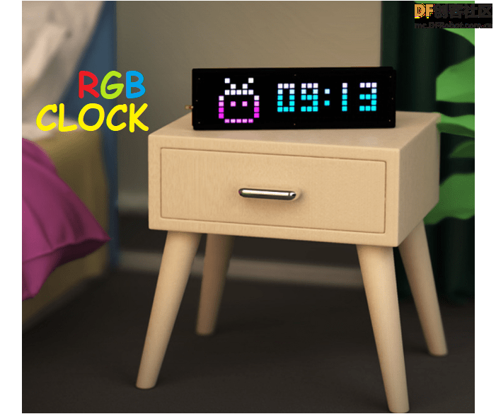
马上要过五一了,这周给大家分享一个用ESP8266做一个高颜值的RGB时钟的项目,这个时钟还具有自动亮度控制功能并配备了温度传感器!
材料准备
第1步: 准备工作
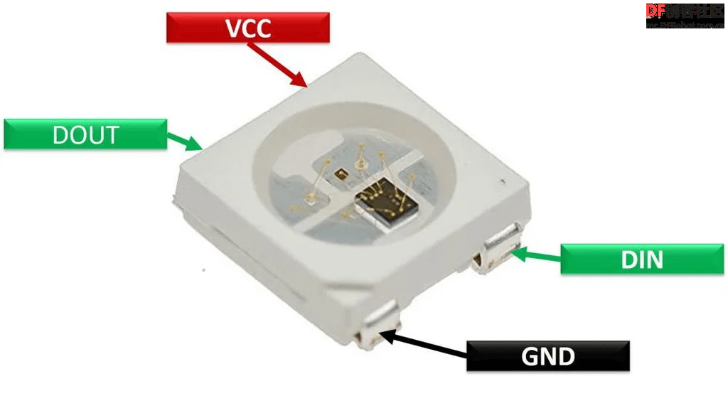
Neo Pixel是可寻址的LED,我们可以通过编程,让它显示任何一种颜色或者数字。
Neo Pixel有不同的smd封装,这个项目使用的是Ws2812b-5050 mini RGB。
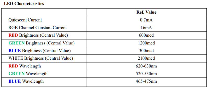
这种迷你LED的额定电压为3.0V到5.5V,电流为16mA(每个LED)。
NodeMCU有3.3V的稳压器,可以正常驱动所有的LED。
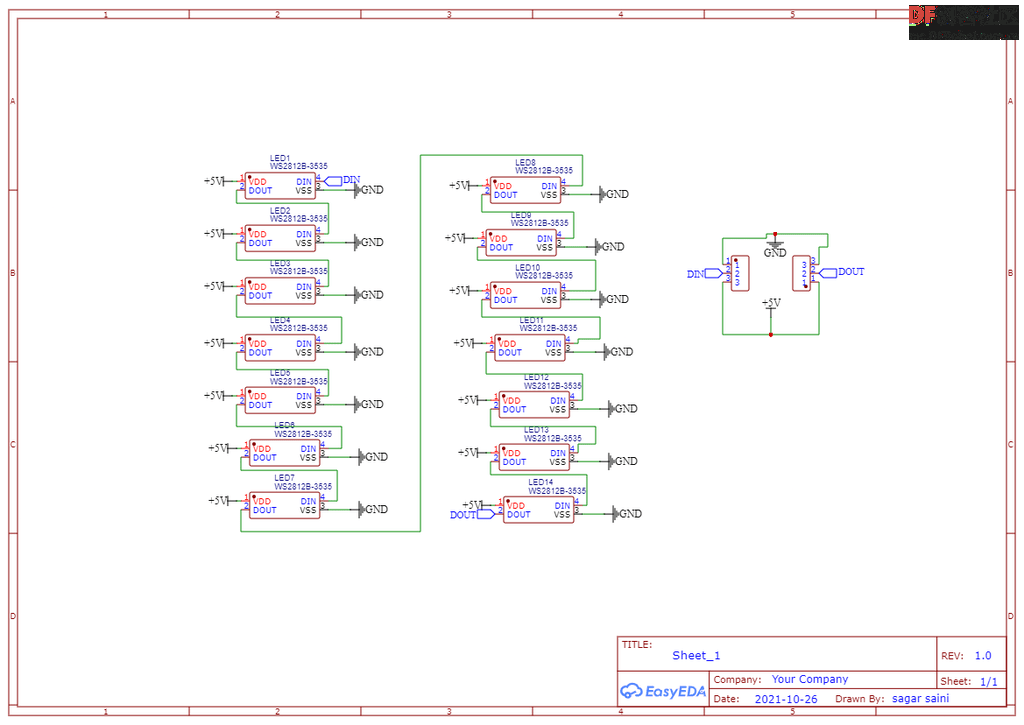
第2步:使用Neo Pixel Led制作7段显示器
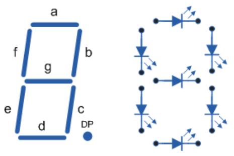
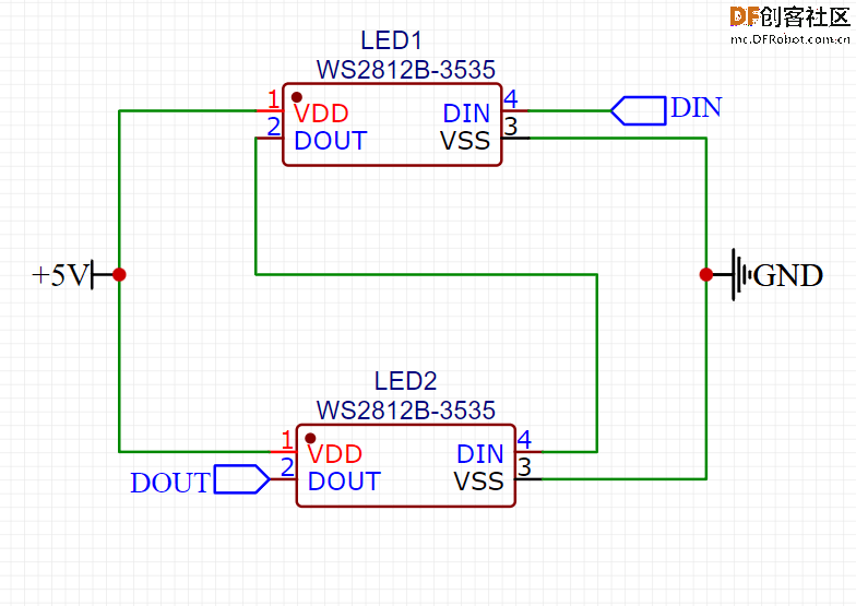
在这里,我们需要把所有的电源并联起来,把所有的数据连接串联起来,使用7段显示方法,如上图连接所有的LED。
每段有2个LED,整个面板总共有14个LED。
我们需要4个面板来显示时间(2个显示小时,2个显示分钟)。
当然还可以再连接两个面板来显示秒/任何其他数值,或者温度。
不管怎么连接,记住总是要把第一个面板的DOUT连接到第二个面板的DIN。
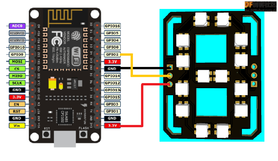
第3步:连接仪表盘
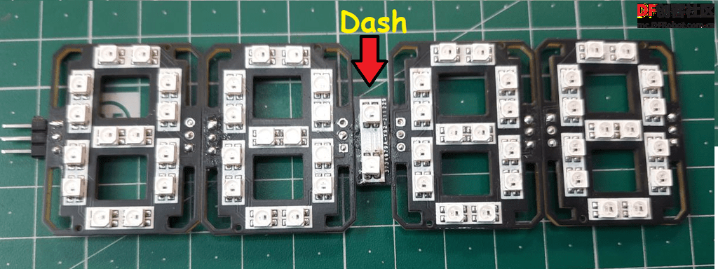
为了连接小时和分钟面板,在两面板之间有一个小的PCB板,名为Dash,包含了2个LED作为二进制数字,这2个LED灯每隔一秒就会发光一次。
第四步:NodeMCU/ESP8266介绍
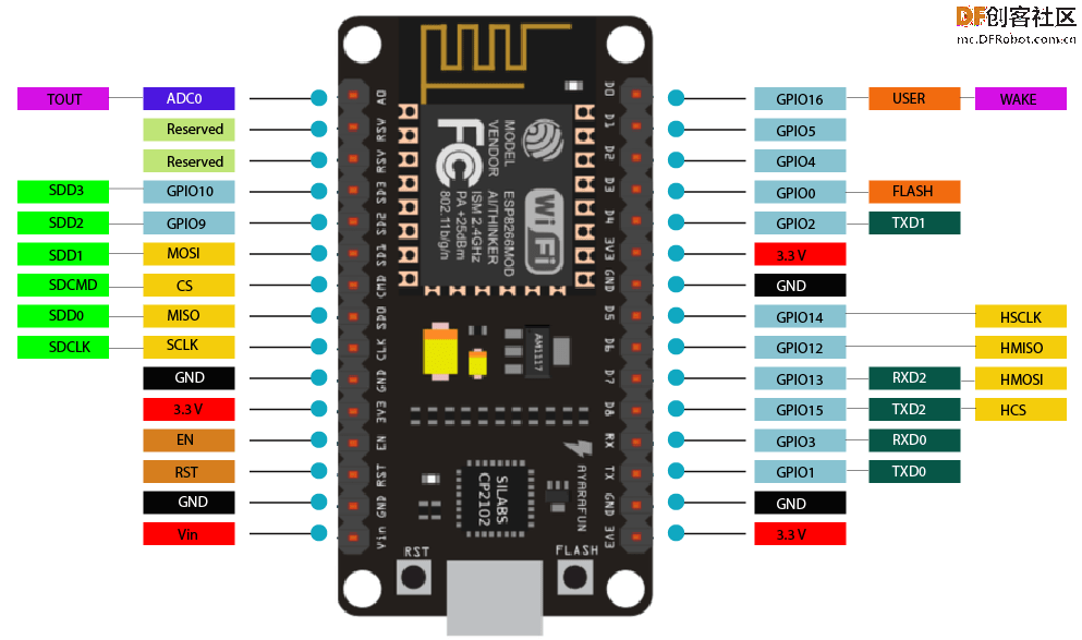
ESP8266集成了一个32位Tensilica处理器,标准的数字外围接口。
我们的ESP8266具有板载Wi-Fi支持,通过它我们可以连上互联网调整时间,而不需要任何RTC(实时时钟)模块。
这样子的话可以减少连接,使整个项目变得更简单一些。
第5步:代码中支持的功能
如果使用本文提供的代码,那么我们可以在这个7段时钟中增加2个额外的功能:
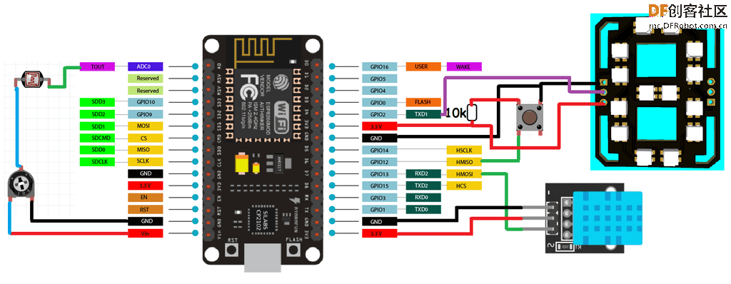
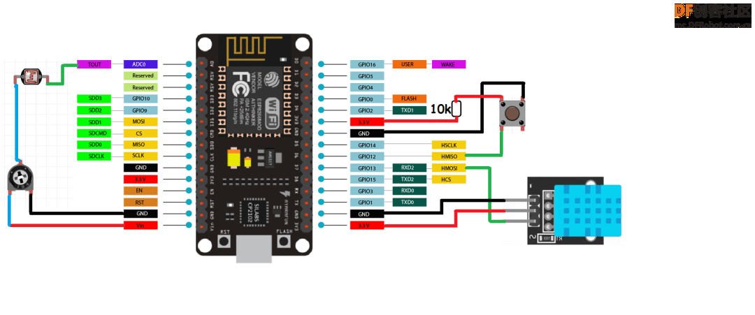
1. 使用触觉开关的温度和湿度显示
在13号针脚上添加一个DHT11传感器,在12号针脚上添加一个触觉按钮,可以在屏幕上获得摄氏或华氏的温度值。
用一个10k电阻将按钮的第12针脚连接到5V,另一端连接到GND。也就是说,当按钮针脚被拉到GND时,显示器将显示温度读数。如果没有这个温度传感器,代码也可以工作,所以如果你想让项目简单一点,也可以不需要这些连接。
2. 使用引脚A0的LDR传感器进行亮度控制
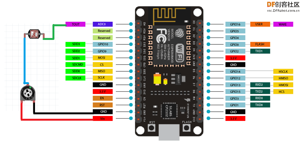
通过在A0引脚上做一个电阻分压器网络,添加一个带有10k电阻的LDR传感器,可以相应地改变亮度。
白天的亮度高,晚上的亮度低。如果你不想要可调节亮度,这部分代码也可以在没有这些传感器的情况下工作,它将会锁定在默认设置。
第7步:视频演示
第8步:7-段时钟
现在,我们有4个面板和一个Dash(仪表盘)。
根据上面GIF图来连接面板和仪表盘;将2个面板串联在一起。
然后使用上面给出的原理图连接NodeMCU。
第9步:代码
首先使用库来初始化代码:
- #include <ESP8266WiFi.h>
- #include <Adafruit_NeoPixel.h>
- #include <WiFiUdp.h>
- #include <NTPClient.h>
- #include <TimeLib.h>
- #include <DHT.h>
- #include <Adafruit_Sensor.h>
定义所有像素、I/O引脚、传感器引脚:
- #define PIXEL_PER_SEGMENT 2 // Number of LEDs in each Segment
- #define PIXEL_DIGITS 4 // Number of connected Digits
- #define PIXEL_PIN 2 // GPIO Pin
- #define PIXEL_DASH 1 // Binary segment
- #define LDR_PIN A0 // LDR pin
- #define DHT_PIN 13 // DHT Sensor pin
- #define BUTTON_PIN 12 // Button pin
对于时间格式,使用Wi-Fi把ESP8266连接到互联网:
- WiFi.begin(ssid, password);
- Serial.print("Connecting.");
- while ( WiFi.status() != WL_CONNECTED )
时间设置:
- void disp_Time() {
- clearDisplay();
- writeDigit(0, Hour / 10);
- writeDigit(1, Hour % 10);
- writeDigit(2, Minute / 10);
- writeDigit(3, Minute % 10);
- writeDigit(4, Second / 10);
- writeDigit(5, Second % 10);
- disp_Dash();
面板上的颜色设置:
- if (index == 0 || index == 1 ) color = strip.Color(0, Brightness, 0);
- if (index == 2 || index == 3 ) color = strip.Color(0, Brightness, 0);
- if (index == 4 || index == 5 ) color = strip.Color(Brightness, 0, 0);
这只是一个简单的介绍,同时代码还有温度和自动时间选项。
温度模式可以通过数字针脚12的开关来选择。
第十步:完整代码
- #include <ESP8266WiFi.h>
- #include <Adafruit_NeoPixel.h>
- #include <WiFiUdp.h>
- #include <NTPClient.h>
- #include <TimeLib.h>
- #include <DHT.h>
- #include <Adafruit_Sensor.h>
-
- #define PIXEL_PER_SEGMENT 2 // Number of LEDs in each Segment
- #define PIXEL_DIGITS 4 // Number of connected Digits
- #define PIXEL_PIN 2 // GPIO Pin
- #define PIXEL_DASH 1 // Binary segment
-
- #define LDR_PIN A0 // LDR pin
- #define DHT_PIN 13 // DHT Sensor pin
- #define BUTTON_PIN 12 // Button pin
-
- // Uncomment the type of sensor in use
- #define DHT_TYPE DHT11 // DHT 11
- //#define DHT_TYPE DHT22 // DHT 22 (AM2302)
- //#define DHT_TYPE DHT21 // DHT 21 (AM2301)
-
- #define TIME_FORMAT 12 // 12 = 12 hours format || 24 = 24 hours format
-
- Adafruit_NeoPixel strip = Adafruit_NeoPixel((PIXEL_PER_SEGMENT * 7 * PIXEL_DIGITS) + (PIXEL_DASH * 2), PIXEL_PIN, NEO_GRB + NEO_KHZ800);
- DHT dht(DHT_PIN, DHT_TYPE);
-
- // set Wi-Fi SSID and password
- const char *ssid = "Hackster";
- const char *password = "Sainisagar7294";
-
- WiFiUDP ntpUDP;
- // 'time.nist.gov' is used (default server) with +1 hour offset (3600 seconds) 60 seconds (60000 milliseconds) update interval
- NTPClient timeClient(ntpUDP, "time.nist.gov", 19800, 60000); //GMT+5:30 : 5*3600+30*60=19800
-
- int period = 2000; //Update frequency
- unsigned long time_now = 0;
- int Second, Minute, Hour;
-
- // set default brightness
- int Brightness = 40;
- // current temperature, updated in loop()
- int Temperature;
-
- bool Show_Temp = false;
-
- //Digits array
- byte digits[12] = {
- //abcdefg
- 0b1111110, // 0
- 0b0110000, // 1
- 0b1101101, // 2
- 0b1111001, // 3
- 0b0110011, // 4
- 0b1011011, // 5
- 0b1011111, // 6
- 0b1110000, // 7
- 0b1111111, // 8
- 0b1110011, // 9
- 0b1001110, // C
- 0b1000111, // F
- };
-
- //Clear all the Pixels
- void clearDisplay() {
- for (int i = 0; i < strip.numPixels(); i++) {
- strip.setPixelColor(i, strip.Color(0, 0, 0));
- }
- strip.show();
- }
-
- void setup() {
- Serial.begin(115200);
- strip.begin();
- strip.show();
-
- dht.begin();
- pinMode(BUTTON_PIN, INPUT);
-
- WiFi.begin(ssid, password);
- Serial.print("Connecting.");
- while ( WiFi.status() != WL_CONNECTED ) {
- delay(500);
- Serial.print(".");
- }
- Serial.println("connected");
- timeClient.begin();
- delay(10);
- }
-
- void loop() {
- if (WiFi.status() == WL_CONNECTED) { // check WiFi connection status
- int sensor_val = analogRead(LDR_PIN);
- Brightness =40;
- timeClient.update();
- int Hours;
- unsigned long unix_epoch = timeClient.getEpochTime(); // get UNIX Epoch time
- Second = second(unix_epoch); // get seconds
- Minute = minute(unix_epoch); // get minutes
- Hours = hour(unix_epoch); // get hours
-
- if (TIME_FORMAT == 12) {
- if (Hours > 12) {
- Hour = Hours - 12;
- }
- else
- Hour = Hours;
- }
- else
- Hour = Hours;
- }
-
- if (digitalRead(BUTTON_PIN) == LOW) {
- Show_Temp = true;
- }
- else
- Show_Temp = false;
-
- if (Show_Temp) {
- Temperature = dht.readTemperature();
- Serial.println(Temperature);
- clearDisplay();
- writeDigit(0, Temperature / 10);
- writeDigit(1, Temperature % 10);
- writeDigit(2, 10);
- strip.setPixelColor(28, strip.Color(Brightness, Brightness, Brightness));
- strip.show();
- delay(3000);
- clearDisplay();
- Show_Temp = false;
- }
- while (millis() > time_now + period) {
- time_now = millis();
- disp_Time(); // Show Time
- }
- }
-
- void disp_Time() {
- clearDisplay();
- writeDigit(0, Hour / 10);
- writeDigit(1, Hour % 10);
- writeDigit(2, Minute / 10);
- writeDigit(3, Minute % 10);
- writeDigit(4, Second / 10);
- writeDigit(5, Second % 10);
- disp_Dash();
- strip.show();
- }
-
- void disp_Dash() {
- int dot, dash;
- for (int i = 0; i < 2; i++) {
- dot = 2 * (PIXEL_PER_SEGMENT * 7) + i;
- for (int j = 0; j < PIXEL_DASH; j++) {
- dash = dot + j * (2 * (PIXEL_PER_SEGMENT * 7) + 2);
- Second % 2 == 0 ? strip.setPixelColor(dash, strip.Color(0,Brightness ,0)) : strip.setPixelColor(dash, strip.Color(0, Brightness,0));
- }
- }
- }
-
- void writeDigit(int index, int val) {
- byte digit = digits[val];
- int margin;
- if (index == 0 || index == 1 ) margin = 0;
- if (index == 2 || index == 3 ) margin = 1;
- if (index == 4 || index == 5 ) margin = 2;
- for (int i = 6; i >= 0; i--) {
- int offset = index * (PIXEL_PER_SEGMENT * 7) + i * PIXEL_PER_SEGMENT + margin * 2;
- uint32_t color;
- if (digit & 0x01 != 0) {
- if (index == 0 || index == 1 ) color = strip.Color(Brightness, 0, Brightness);
- if (index == 2 || index == 3 ) color = strip.Color(Brightness, 0,Brightness);
- if (index == 4 || index == 5 ) color = strip.Color(Brightness, 0, 0);
- }
- else
- color = strip.Color(0, 0, 0);
-
- for (int j = offset; j < offset + PIXEL_PER_SEGMENT; j++) {
- strip.setPixelColor(j, color);
- }
- digit = digit >> 1;
- }
- }
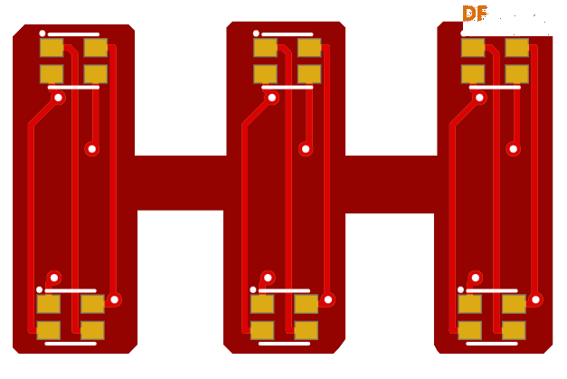
第11步:完整电路图(高清版本文末下载)
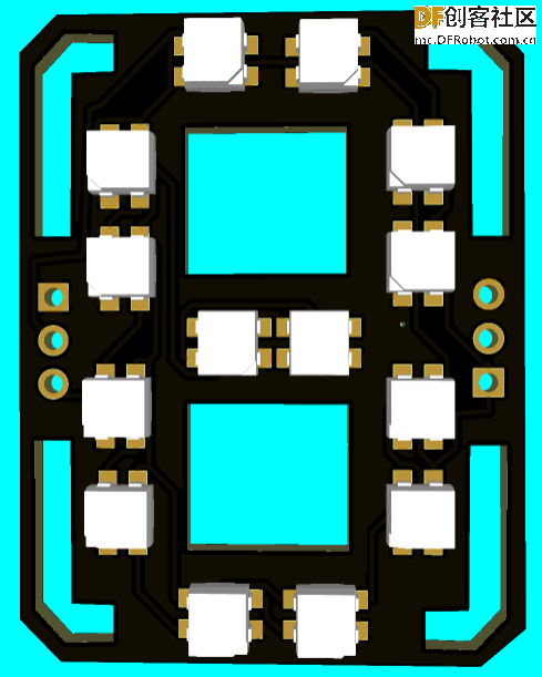
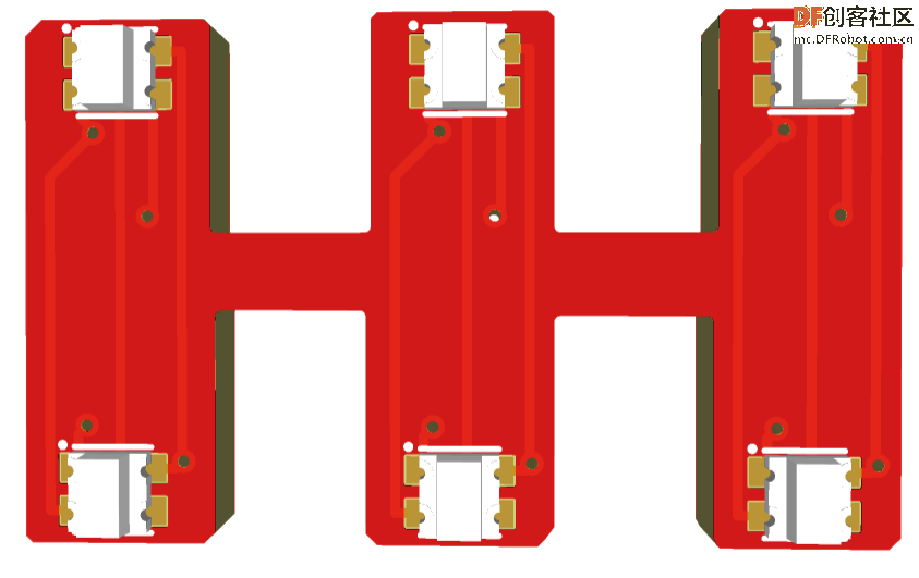
第12步:PCB设计(面板部分)
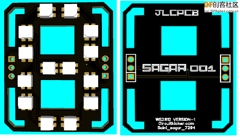
主要的PCB设计,用于显示数字和其他字母。
第13步:PCB设计(Dash部分)
第14步:故障排除
- DIN总是与DOUT串联在一起,如果接反了或从任何地方断开了,整个装置就会停止工作;
- 按上面的图连接Dash;
- 确保所有的连接都焊接好,干焊会导致数据值和颜色的改变;
- 在焊接时,不要把印刷电路板加热太多,温度保持在300度。
第15步:完整展示
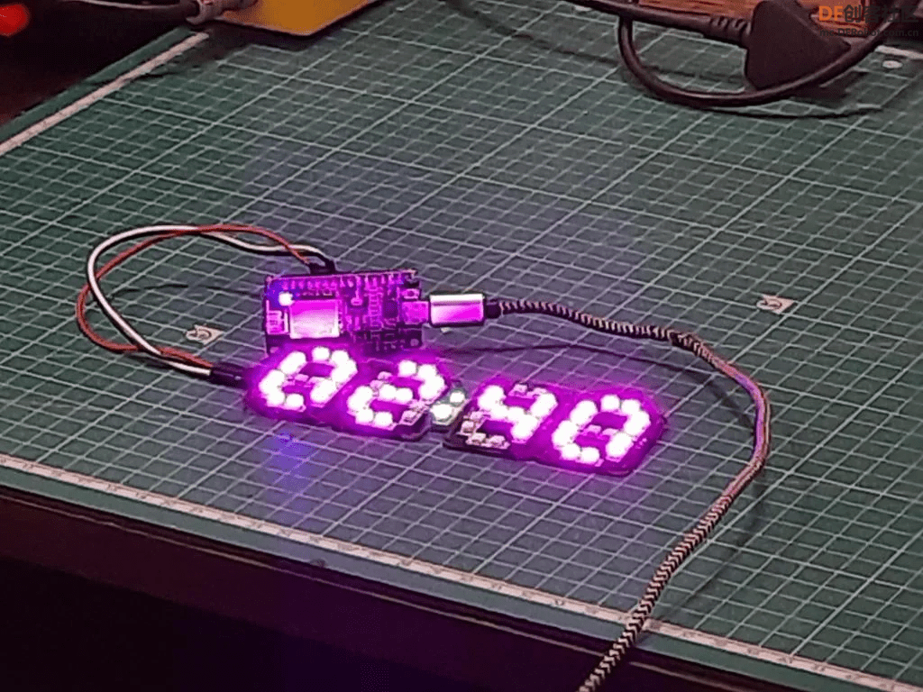
喜欢大家喜欢这个项目,提前祝大家五一快乐!
原文链接:https://www.instructables.com/RGB-7-Segment-Clock-Using-ESP8266/
原作者:sainisagar7294
译文首发于:DF创客社区
转载请注明原作者及出处
| 


 沪公网安备31011502402448
 置顶卡
置顶卡 变色卡
变色卡 千斤顶
千斤顶


 萌萌哒新人
萌萌哒新人
 宣传大使
宣传大使
 小蘑菇
小蘑菇
 ARD DAY
 编辑选择奖
编辑选择奖
 摸鱼团员
摸鱼团员
 编辑选择奖
编辑选择奖
 编辑选择奖
编辑选择奖
 编辑选择奖
编辑选择奖


