|
16425| 5
|
[项目] 女神生日不知道送什么礼物,不如手工打造一颗arduino心愿球 |

|
心愿球 由黄铜棒制成,采用自由球形态连接 18 颗发光 LED。  硬件材料 1*黄铜棒 18*贴片 LED 1*ATmega8L 芯片 1*CR2032 纽扣电池 1*开关 天体 主要挑战是用黄铜棒弯成圆形,看起来像一个天体。我用 6 根铜棒竖直排列(经度)和 3 根铜棒 水平排列(纬度)构建一个球。这样子就总共有 18 个交叉点用于焊接 LED。在球体的底部有一个 环形开口,为的是最终可以更好的放入芯片、电池等元器件。 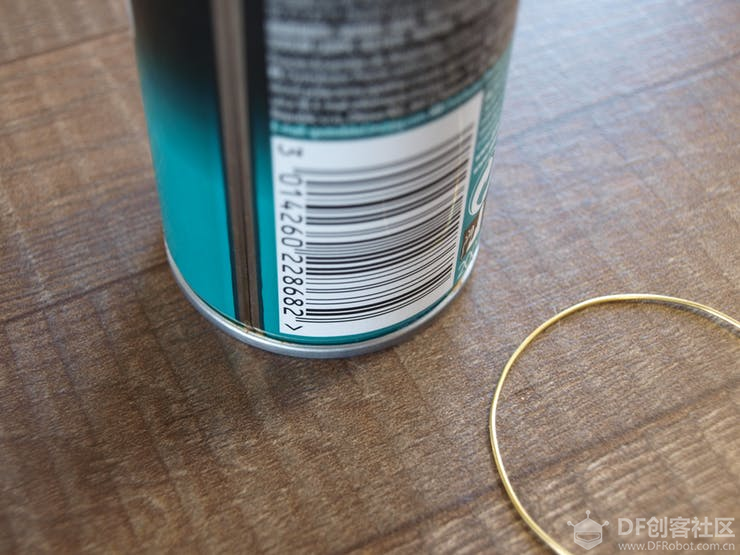 首先,把铜棒弯成圆形。我最开始找到一个直径为 50 毫米的铁罐,可以在弯曲时用底盖固定铜 棒。弯曲铜棒后,把其剪断并把两端焊接在一起,形成一个漂亮的环。在一张纸上画出相同的形 状,可以帮助你匹配最完美的圆形。为了制作更小的圆环,我使用了其他直径的瓶。使用与你的 直径相匹配的东西,身边上到处都是圆形的东西! 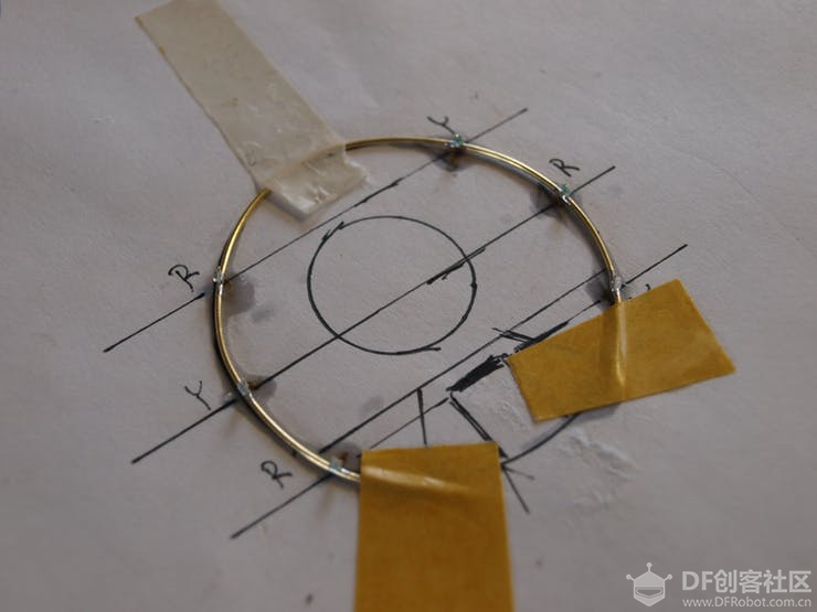 接下来,我把 LED 焊接到三个 50mm 环上。我在一张纸上画了一个模板。我采用是黄色和红色 LED。黄色和红色,因为它比蓝色或白色更节能。 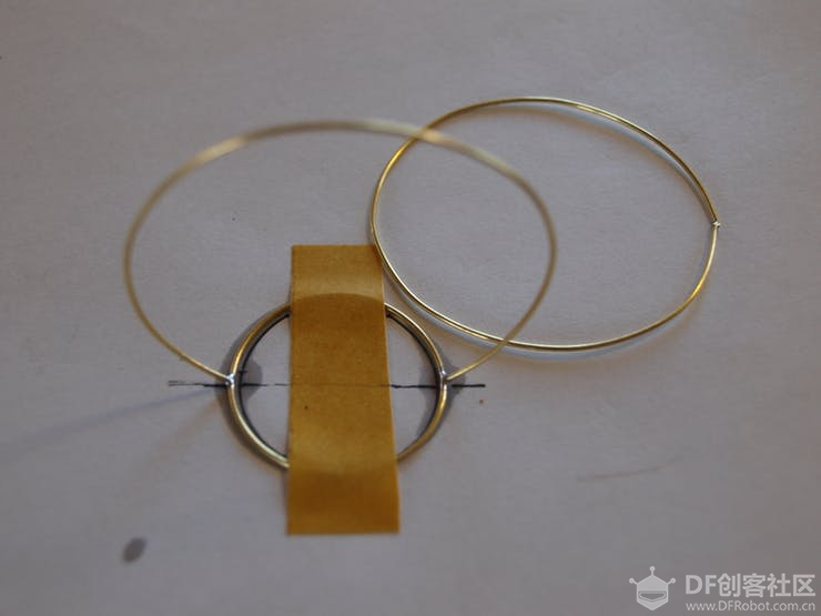 接着,我把带有 LED 的环焊接到基环上。我用一块胶带把基环固定在桌子上,修剪了垂直环的底 部并把它们焊接到环上,形成了一个皇冠。第一个环焊接成一体,第二个和第三个环切成两半, 形成球体的平顶。 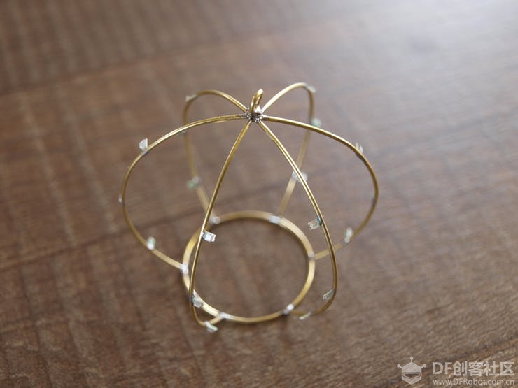 最后一步是最让人沮丧和耗时的。把 LED 与弯曲杆相互连接以形成水平环。我把剩下的环一个一 个地切开,以适应垂直环之间的空间并求佛一样地焊接。 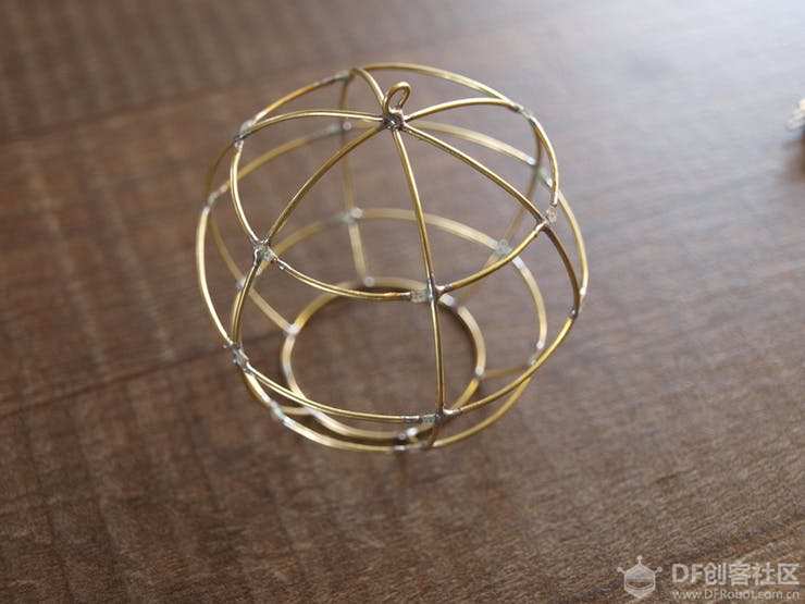 我想到一种放置 LED 的简单方法。 两个 LED 在邻近的垂直环(地面)上彼此面对,它们与一根弯 曲的杆连接,该杆是水平环(电源线)的一部分。最终得到 18 个 LED,分为 9 个部分。 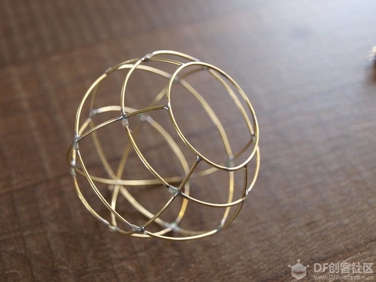 温馨提醒:经常测试 LED 是否仍是好的,否则你需要在最后重做这件事,这是一种可怕的又振奋 人心的测试。 如果你只是希望它发光并且不关心任何动画。你可以立即停止阅读,把 CR2032 纽扣电池和开关放 入内部。通过 68Ω 限流电阻把 LED 与电池连接,就可以使其发光!把电池焊接到黄铜线时,请确 保不要过热,否则可能会导致电池过热。 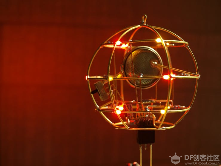 如果你像我一样,爱 Arduino 并希望让它变得聪明并且有一点乐趣,让我们把微控制器放入其 中!我使用的是 ATmega8L 芯片——与 Arduino NANO 相同的封装,但内存更少,功耗更低。L 意 味着它具有 2.7 - 5V 的宽工作电压范围,这在使用 3V 纽扣电池时非常棒。另一方面,由于它是 TQF32 封装,因此焊接到铜棒上是一个不小的挑战,但外观和效果都很好。 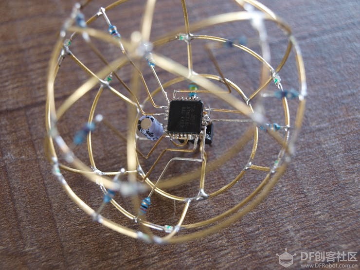 原理图 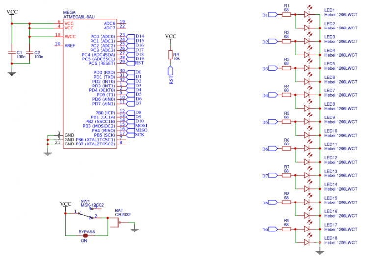 源代码 [mw_shl_code=applescript,true]#define LEDS 9 byte leds[] = { 5, 19, 17, // bottom 6, 1, 15, // middle 8, 21, 13 // top }; #define ON true #define OFF false // variables for pattern timing unsigned long currentMillis = millis(); unsigned long previousMillis = 0; unsigned long millisInterval = 3 00; // variables for software PWM unsigned long currentMicros = micros(); unsigned long previousMicros = 0; // this is the frequency of the sw PWM // frequency = 1/(2 * microInterval) unsigned long microInterval = 250; const byte pwmMax = 100; // fading (for the timing) int fadeIncrement = 1; // typedef for properties of each sw pwm pin typedef struct pwmPins { int pin; int pwmValue; bool pinState; int pwmTickCount; } pwmPin; // create the sw pwm pins // these can be any I/O pin // that can be set to output! const int pinCount = 9; const byte pins[pinCount] = { 5, 19, 17, // bottom 6, 1, 15, // middle 8, 21, 13 // top }; pwmPin myPWMpins[pinCount]; // function to "setup" the sw pwm pin states // modify to suit your needs // this creates an alternating fade pattern void setupPWMpins() { for (int index=0; index < pinCount; index++) { myPWMpins[index].pin = pins[index]; // mix it up a little bit // changes the starting pwmValue for odd and even if (index % 2) myPWMpins[index].pwmValue = 25; else myPWMpins[index].pwmValue = 75; myPWMpins[index].pinState = ON; myPWMpins[index].pwmTickCount = 0; // unlike analogWrite(), this is necessary pinMode(pins[index], OUTPUT); } } void pwmFadePattern() { // go through each sw pwm pin, and increase // the pwm value. this would be like // calling analogWrite() on each hw pwm pin for (int index=0; index < pinCount; index++) { myPWMpins[index].pwmValue += fadeIncrement; if (myPWMpins[index].pwmValue > 100) myPWMpins[index].pwmValue = 0; } } void handlePWM() { currentMicros = micros(); // check to see if we need to increment our PWM counters yet if (currentMicros - previousMicros >= microInterval) { // Increment each pin's counter for (int index=0; index < pinCount; index++) { // each pin has its own tickCounter myPWMpins[index].pwmTickCount++; // determine if we're counting on or off time if (myPWMpins[index].pinState == ON) { // see if we hit the desired on percentage // not as precise as 255 or 1024, but easier to do math if (myPWMpins[index].pwmTickCount >= myPWMpins[index].pwmValue) { myPWMpins[index].pinState = OFF; } } else { // if it isn't on, it is off if (myPWMpins[index].pwmTickCount >= pwmMax) { myPWMpins[index].pinState = ON; myPWMpins[index].pwmTickCount = 0; } } // could probably use some bitwise optimization here, digitalWrite() // really slows things down after 10 pins. digitalWrite(myPWMpins[index].pin, myPWMpins[index].pinState); } // reset the micros() tick counter. digitalWrite(13, !digitalRead(13)); previousMicros = currentMicros; } } void setup() { setupPWMpins(); //pinMode(13, OUTPUT); } void loop() { // this is the magic for sw pwm // need to call this anytime you // have a long operation handlePWM(); // check timer for fading pattern // this would be the same // if we used analogWrite() currentMillis = millis(); if (currentMillis - previousMillis >= millisInterval) { // moved to own funciton for clarity pwmFadePattern(); // setup clock for next tick previousMillis = currentMillis; } } [/mw_shl_code] |


 沪公网安备31011502402448
© 2013-2026 Comsenz Inc. Powered by Discuz! X3.4 Licensed

 置顶卡
置顶卡 变色卡
变色卡 千斤顶
千斤顶