今天给大家带来一个 180° 金属带模拟值反馈舵机的应用,就是利用该舵机设计一个简易机械臂,该机械臂具有学习功能,当我们给它设定一个动作,设计完成后,它能根据我设计的动作自动进行学习,复刻我设定的动作。
当当,下面是我们使用到的角色~
主角!! 还有其他的小伙伴 下面我们康康它们长什么样子吧
开箱主角介绍: 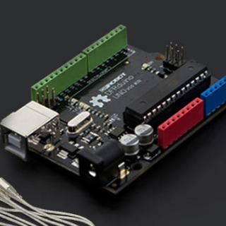 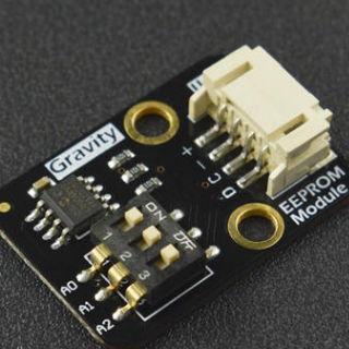
 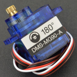
软件介绍: 接下来我们要进行安装环境得安装,这里我简单给大家介绍一下 我们开发使用的是 DFRduino UNO R3,首先我们要先下载 Arduino 编译环境 下载完成后进行驱动安装,找到下载文件
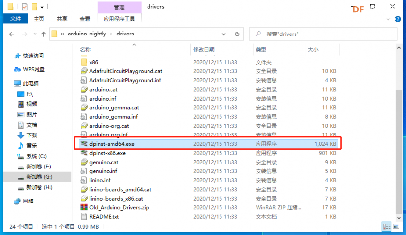
驱动安装完成后我们就可以愉快的在 Arduino IDE 上进行开发啦! 写的不好,不要见怪,小伙伴们也可以参考下面链接详细里了解 arduino 的使用教程。
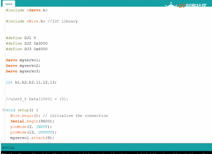
接下来我们简单直接一点,直接上程序。
- #include <Servo.h>
-
- #include <Wire.h> //I2C library
-
-
- #define DJ1 0
- #define DJ2 0x3000
- #define DJ3 0x6000
-
- Servo myservo1;
- Servo myservo2;
- Servo myservo3;
-
- int h1,h2,h3,l1,l2,l3;
-
-
- //uint8_t Data[1000] = {0};
-
- void setup() {
- Wire.begin(); // initialise the connection
- Serial.begin(9600);
- pinMode(3, INPUT);
- pinMode(13, OUTPUT);
- myservo1.attach(9);
- myservo2.attach(8);
- myservo3.attach(7);
-
- Init();
- while (Botton(3) == 0);
-
-
- }
-
- void loop() {
- int val = readAngle();
- writingAngle( val);
- }
-
- bool Botton(int inPin)
- {
- bool ret = 0;
- if (digitalRead(inPin)) {
- delay(100);
- if (digitalRead(inPin)) {
- ret = 1;
- digitalWrite(13, HIGH);
- while (digitalRead(inPin));
- digitalWrite(13, LOW);
- delay(100);
- }
- }
- return ret;
- }
-
- int readAngle(void)
- {
- int Length = 0;
- byte dat;
-
- myservo1.detach();
- myservo2.detach();
- myservo3.detach();
-
- while (Botton(3) == 0) {
- dat = map(analogRead(0), l1, h1, 0, 180);
- i2c_eeprom_write_byte( 0x57, Length, dat );
-
- dat = map(analogRead(1), l2, h2, 0, 180);
- i2c_eeprom_write_byte( 0x57, DJ2 + Length, dat );
-
- dat = map(analogRead(2), l3, h3, 0, 180);
- i2c_eeprom_write_byte( 0x57, DJ3 + Length, dat );
-
- Length++;
- if (Length >= 1023) {
- break;
- }
- }
- return Length;
- }
-
- void writingAngle( int Length)
- {
- int i = 0;
- int flag = 1;
-
- myservo1.attach(9);
- myservo2.attach(8);
- myservo3.attach(7);
- while (flag) {
- for (int i = 0; i < Length; i++) {
- myservo1.write(i2c_eeprom_read_byte(0x57, i + DJ1));
- myservo2.write(i2c_eeprom_read_byte(0x57, i + DJ2));
- myservo3.write(i2c_eeprom_read_byte(0x57, i + DJ3));
- if (Botton(3)) {
- flag = 0;
- break;
- }
- delay(18);
- }
- }
- }
-
- void i2c_eeprom_write_byte( int deviceaddress, unsigned int eeaddress, byte data )
- {
- int rdata = data;
- Wire.beginTransmission(deviceaddress);
- Wire.write((int)(eeaddress >> 8)); // MSB
- Wire.write((int)(eeaddress & 0xFF)); // LSB
- Wire.write(rdata);
- Wire.endTransmission();
- delay(6);
- }
-
-
- byte i2c_eeprom_read_byte( int deviceaddress, unsigned int eeaddress )
- {
- byte rdata = 0xFF;
- Wire.beginTransmission(deviceaddress);
- Wire.write((int)(eeaddress >> 8)); // MSB
- Wire.write((int)(eeaddress & 0xFF)); // LSB
- Wire.endTransmission();
- Wire.requestFrom(deviceaddress, 1);
- if (Wire.available()) rdata = Wire.read();
- return rdata;
- }
-
- void Init()
- {
- myservo1.write(0);
- myservo2.write(0);
- myservo3.write(0);
- delay(1000);
-
- l1= analogRead(0);
- l2= analogRead(1);
- l3= analogRead(2);
-
- myservo1.write(180);
- myservo2.write(180);
- myservo3.write(180);
- delay(1000);
-
- h1= analogRead(0);
- h2= analogRead(1);
- h3= analogRead(2);
-
- myservo1.write(90);
- myservo2.write(90);
- myservo3.write(90);
- delay(1000);
- }
我们按下图一端连接开发板,另一端连接到电脑USB口 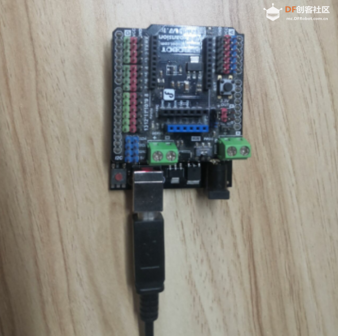
代码写好后,我们编译程序通过发现没有问题后,点击上传程序。 好了程序编译上传成功了,接下来我们先测试效果,看看能达到我们的预期效果没。
测试: 完成后我们发现无法同时驱动三个舵机,我们需要在 SERVO_PWR 接入一个 5V 电源,保证能同时驱动 3 个舵机。 电源接入完成后,我们进行测试,测试结果如下。 我们可以看到,舵机可以进行动作的学习了。接下来我们就可以安装简易的机械臂了。
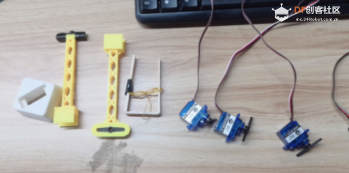
安装步骤: 下面是机械臂材料一览图,这是我们机械臂要用的东西 首先是底座,我们找到底座,通过卡槽将舵机装入里面,这样,我们的机械臂底座的安装就完成啦。 接着我们安装两个臂,我们通过卡槽,将舵机固定好,到此,我们的简易机械臂就初据模型啦,我们就只差一个夹子啦。 我们通过卡槽安装好即可
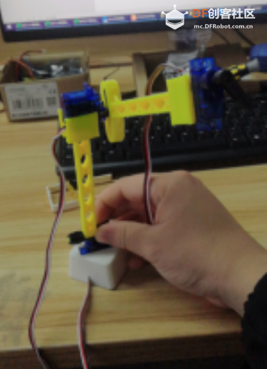
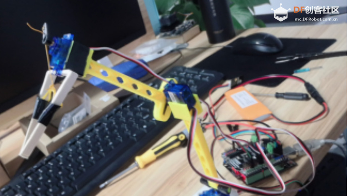
最后一步我们安装我们的夹子(夹子做的有点 low,大家见谅),夹子我们使用了一根橡皮筋和两个活动的夹子端,通过舵机旋转带动橡皮筋来实现夹取和放下。 至此,我们的简易机械臂就安装完成啦,下面是简易舵机成品图。
布线和接线: 接下来我们把三个舵机分别连接到开发板得 9,8,7 号引脚,模拟量接口分别接入模拟口 0,1,2,这里建议 9 号引脚舵机连接0号模拟口,8 号引脚舵机连接1号模拟口,7 号引脚舵机连接 2 号模拟口。安装完成后,我们需要把它的连接线用胶布缠一下,避免看上去很乱。 这样,我们的完整简易机械臂就安装设计完成了,下面我们看看它的实际效果。相信已经迫不及待想要看我们的实际效果了吧。话不多说,我们直接看实际效果吧!
实际效果: 应用实物如下,我们可以看到机械臂可以自动学习我们设置的动作
这样一个简单的机械臂就设计完成了,大家可以利用带反馈值做一些其他有趣的应用。 这样一个反馈舵机,能做很多有趣的应用,喜欢的朋友可以参考链接购买玩起来哟! 感谢大家的阅读,希望能对您有帮助,下面再次附上我们主角的链接。
| 



 沪公网安备31011502402448