前言
原创文章,转载引用务必注明链接。水平有限,如有疏漏,欢迎指正交流。由于个人时间精力有限,欢迎互相交流,不欢迎不认真看文档的伸手党。
我们之前介绍了为 F10x 主板烧录 stm32duino-bootloader,为 F4xx 主板烧录 hid-bootloader ,后者虽然麻烦,但是真的香,不需要手动设置引脚高低电平来使能/退出 bootloader,还有想办法重置 mcu 了。本文介绍如何为 F10x 设备移植 hid-bootloader,相比麻烦一些,主要是没有文档。如果你看着累看不懂没关系,因为是流水账不是新手教程,如果想为自己的主板适配 hid-bootloader,遇到坑可以来参考下。我没有深入的STM32开发经验,肯定有说的不对的地方,标必看的那个必须看哈。
目的
- 方便我的2nd mcu 使用(STM32F103C6T6)
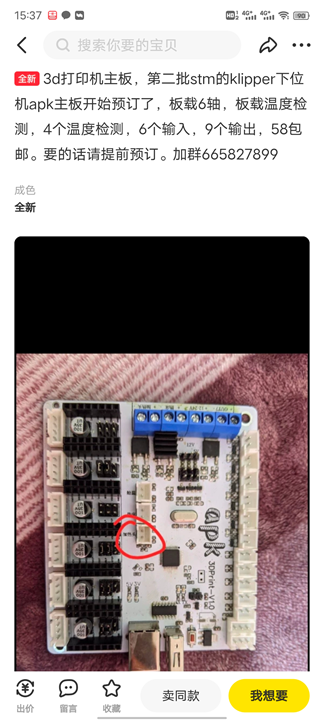
- 未来 58块钱的 APK 3D打印主板可能用得上(同上芯片,flash 太小了,不是我做的)
hid-bootloader 优点:
本文内容比较多,但是不看懂参数的话,你都不知道如何修改移植。
我们在前面介绍使用 stm32duino bootloader,通过上位机来控制 bl 使能引脚,重启 mcu 来进入、退出 bl,从而烧录固件。缺点:
- 需要上位机接线
- 需要手动进入、退出 bootloader,比较麻烦
- 不支持 STM32F4xx MCU
软件环境:Raspberry Pi OS buster on RaspberryPi 400,gcc-6
1、hid-bootloader 介绍
我们看一下关系:
Arksine Version -> Serasidis Version -> bootsector -> stm32duino-bootloader -> maple-bootloader,一些文档互相补充查看。其中 F10x 部分代码结构类似 stm32duino bl,看着难受。
前情提要:port stm32duino bl for blue header
Arksine (Moonraker API 作者) Fork 了一份 hid-bootloader ,并修改了 hid-flash 工具以适配 Klipper,从而实现 make flash 命令直接刷机。我们以此为蓝本进行修改,适配我们的老朋友 Blue Header。

2、hid-bootloader for F1 源码介绍
我们先看看修改了哪些部分,并且对照 BTT-SKR-Mini-E3 v1.2/v2.0 主板硬件原理图,方便理解:
需要修改的地方包括:
```c++
// bootloader\F1\Inc\config.h 注释版 by 思兼
elif defined TARGET_BTT_SKR_MINI_E3
// [1] TODO: 配置 LED 指示灯
    #define LED1_CLOCK                RCC_APB2ENR_IOPAEN /* 使能 GPIOA 时钟 */
    #define LED1_BIT_0
    #define LED1_BIT_1
    #define LED1_MODE       INIT_REG(GPIOA->CRH, 15, GPIO_CRH_MODE15)
    #define LED1_ON                        WRITE_REG(GPIOA->BSRR, GPIO_BSRR_BS15)
    #define LED1_OFF                WRITE_REG(GPIOA->BSRR, GPIO_BSRR_BR15)

// [2] TODO: [Optional] 配置 USB_DISC 引脚,用于枚举和设备RESET,没有可以不设置,必要时禁用DEBUG等
    #define DISC_CLOCK                RCC_APB2ENR_IOPCEN
    #define DISC_BIT_0
    #define DISC_BIT_1
    #define DISC_MODE                INIT_REG(GPIOC->CRH, 13, GPIO_CRH_CNF13_0 | GPIO_CRH_MODE13)
    #define DISC_HIGH                WRITE_REG(GPIOC->BSRR, GPIO_BSRR_BS13)
    #define DISC_LOW                WRITE_REG(GPIOC->BRR, GPIO_BRR_BR13)

    #define DISABLE_DEBUG   AFIO_MAPR_SWJ_CFG_JTAGDISABLE
    #define AFIO_CLOCK      RCC_APB2ENR_AFIOEN /*!< Alternate Function I/O clock enable */

// [3] TODO: 配置使能bl的引脚
    #ifdef ENABLE_BUTTON
    // Use PA2 on SKR Mini E3 as the Button to check, 在E3上该引脚默认拉高,拉低进入bl。CHECK_BOOT为1时进入bl。
    #define BOOT_CLOCK RCC_APB2ENR_IOPAEN
    #define CHECK_BOOT (READ_BIT(GPIOA->IDR, GPIO_IDR_IDR2) == 0)
    #define BOOT_BIT_0  INIT_REG(GPIOA->CRL, 2, GPIO_CRL_CNF2_1)
    #define BOOT_BIT_1
    #define BOOT_SETUP  WRITE_REG(GPIOA->BSRR, GPIO_BSRR_BS2)
    #else
    // No button
    #define CHECK_BOOT 0
    #endif

    // [4] TODO: 配置 PAGE_SIZE,当为 High Density Device 时需要启用
    #ifdef PAGE_SIZE
    #undef PAGE_SIZE
// 2KB for hid-bl
    #define PAGE_SIZE 2048
    #endif

// 晶振定义,参考
/* CRISTAL 12MHz */
    // #define XTAL12M                1

    // Enable the internal pull-down on PB2 pin. By default, PB2
    // is in FLOATING input mode.
    // #define PB2_PULLDOWN
// bootloader\F1\Src\main.c
/* If:
-
- PB2 (BOOT 1 pin) is HIGH or
-
- no User Code is uploaded to the MCU or
-
- a magic word was stored in the battery-backed RAM
- registers from the Arduino IDE
- then enter HID bootloader...
*/
// ENABLE引脚使能、没有上传用户程序、magic word 代码可以触发进入 bl。
说实话,这个配置文件相比 F4 和 stm32duino 真是不友好,一点注释冇。多方查阅资料,个人注释如下:
LED:
- 查阅主板原理图,找到板载LED定义即可,以
PA15 为例:
DISC
DISC 没看懂,搜了一下原本以为是 ADC 的 间断模式(Discontinuous Mode),感觉不对,对照原理图,最后发现原来是类似 Maple Mini 板上面的枚举控制引脚(Disconnect Pin,USB_DISC),这里的作用就是 reset mcu。
Also Note: Use GCC 4.8 (not 4.9 or newer, as those versions have more aggressive optimisation which cause hardware registers to be read incorrectly and consequently the bootloader does not work) 【STM32duino-bootloader】
Additionally, the bootloader now works with "generic" STM32F103 boards that do not have the additional USB reset hardware which all Maple and Maple mini boards have.
——Source:STM32duino-bootloader
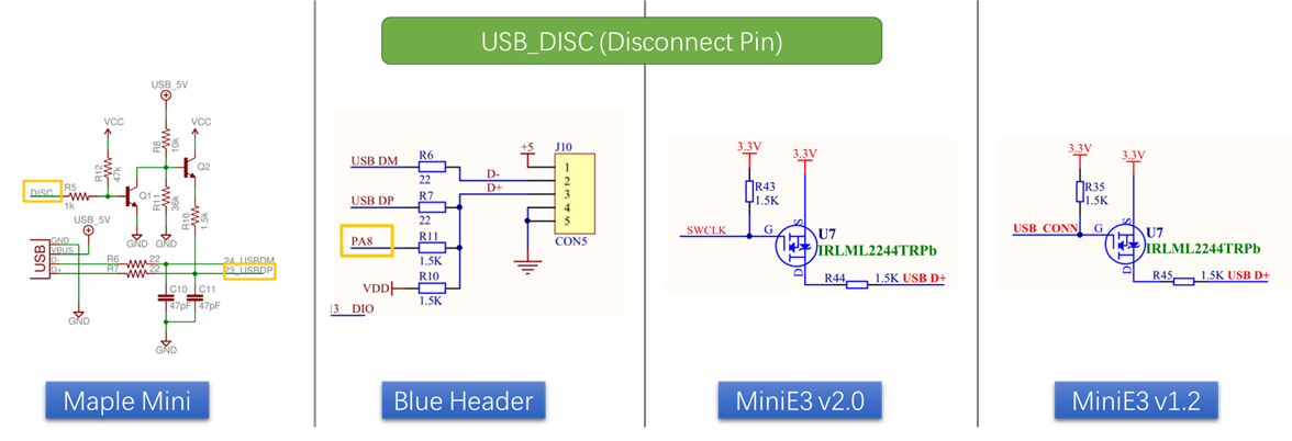
没有DISC引脚如何Reset?
我们同时发现,目前的很多主板都没有 USB_DISC 引脚,那么如何重置mcu呢?
In order to disconnect the device from the host, a USB_DISC pin is asserted (e.g. on Maple, this is PC12). Alternatively, the NVIC can be directly configured to disable the USB LP/HP IRQ's.
—— Source:libmaple
关于 嵌套向量中断控制器(NVIC) 我们可以不了解。具体方法是设置 USB D+ 引脚为输出,然后可以在多数设备上实现reset功能。
The BLUEPILL boards don't actually have a USB_DISC_PIN. To simulate a USB reset sequence, we have been setting the USB D+ pinmode to an output, setting the pin low, delaying for the usb reset period then setting the mode back to an input so that the pull up resistor pulls the pin high. Then the nomal USB init sequence is run. The code as written seems to expect a real USB_DISC_PIN that would have an NPN transistor. The BLUE PILL does not have any hardware like that.
——Source: STM32F1 merged
以及这里:
On "generic" boards, the USB reset (to force re-enumeration by the host), is triggered by reconfiguring the USB D+ line (PA12) into GPIO mode, and driving PA12 low for a short period, before setting the pin back to its USB operational mode. This USB reset method was written by @Victor_pv. Note: It is not guaranteed to work on all "generic" STM32 boards, and relies on PA12 having a pull-up resistor of around 1.5k - however most "generic" boards seem to have this. Its unclear if this method to reset the USB bus conforms precisely to the USB standard, but it seems to work fine on all PCs, Macs and Linux boxes on which it's been tested - and seems usable for hobby / non commericial / non-critical systems.
——Source:STM32duino-bootloader
这个大家都知道,用于控制手动进入 bootloader 的,CHECK_BOOT 为 1 时进入bl,由于miniE3的PA2引脚默认拉高,所以使用上面的方式。
我的BH板PB2(BOOT1)引脚默认拉低,所以不用修改添加这句。
对于有的PB2或者别的使能引脚悬空的,可以手动内部拉低,例如#define PB2_PULLDOWN。
PAGE_SIZE
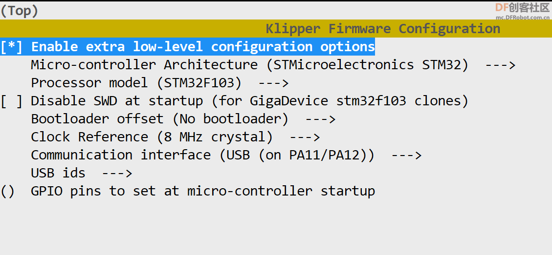
当为 High Density Device 时需要设置。
If you want to use a High Density Device such as STM32F103RCT6 on MiniE3, then you have to add an extra argument to the make command.
- make_all_hd.bat
- PAGE_SIZE=2048
那么什么是 HD Device,哪些是 hdd?看两张图:
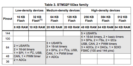
source:What does "Low density device" mean? About STM8 / STM32
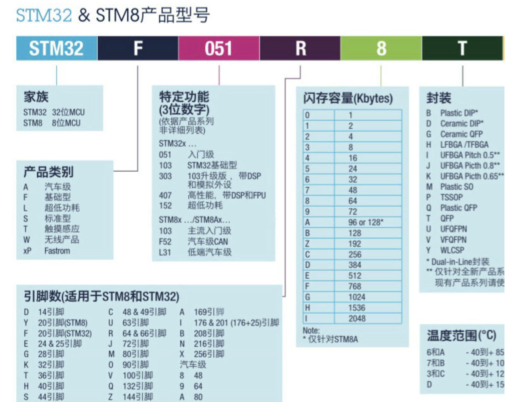
source:一张图看懂STM32芯片型号的命名规则
由此可知,我们的bh板mcu芯片为 STM32F103C8T6,flash 为 64KB,属于 Medium Density Device ,不需要启用该参数。而 miniE3使用 STM32F103RCT6,flash 为256K,需要启用。实际上,第二位为C及以上则需要启用。
```c++
// bootloader\F1\Inc\config.h 注释版 by 思兼
// LED_PIN位于PB8,DISC_PIN位于PA8, Enable_Button_PIN使用PB2(BOOT1),默认拉低,属于Medium Density Device,不需要设置PAGE_SIZE。
// 所以:设置DISC,无需设置ENABLE_BUTTON和PAGE_SIZE。
// BRR - Bit Reset Register
// BSRR - Bit Set Reset Register
    #define LED1_CLOCK                RCC_APB2ENR_IOPBEN
    #define LED1_BIT_0
    #define LED1_BIT_1
    #define LED1_MODE       INIT_REG(GPIOB->CRH, 8, GPIO_CRH_MODE8) /*0b0011 outputMode,0-7 CRL,8-15 CRH*/
    #define LED1_ON                        WRITE_REG(GPIOB->BSRR, GPIO_BSRR_BS8) /*0b000100000000 set pb8 HIGH*/
    #define LED1_OFF                WRITE_REG(GPIOB->BSRR, GPIO_BSRR_BR8) /*0b000100000000|0000000000000000 upper set pb8 LOW*/

    #define DISC_CLOCK                RCC_APB2ENR_IOPAEN
    #define DISC_BIT_0
    #define DISC_BIT_1
    #define DISC_MODE                INIT_REG(GPIOA->CRH, 8, GPIO_CRH_CNF8_0 | GPIO_CRH_MODE8)
    #define DISC_HIGH                WRITE_REG(GPIOA->BSRR, GPIO_BSRR_BS8)
    #define DISC_LOW                WRITE_REG(GPIOA->BRR, GPIO_BRR_BR8)

    #define DISABLE_DEBUG   AFIO_MAPR_SWJ_CFG_DISABLE
    #define AFIO_CLOCK      RCC_APB2ENR_AFIOEN

    // #ifdef ENABLE_BUTTON
    // // Use PA3 on SKR Mini E3 as the Button to check
    // #define BOOT_CLOCK RCC_APB2ENR_IOPAEN
    // #define CHECK_BOOT READ_BIT(GPIOA->IDR, GPIO_IDR_IDR3) /*0b1000(16bit) read inputMode pa3*/ /* */
    // #define BOOT_BIT_0  INIT_REG(GPIOA->CRL, 3, GPIO_CRL_CNF3_1) /* 0b1000000000000000 inputMode*/
    // #define BOOT_BIT_1
    // #define BOOT_SETUP  WRITE_REG(GPIOA->BSRR, GPIO_BSRR_BR3) /* 0b1000|0000000000000000 pa3 low*/
    // #else
    // // No button
    // #define CHECK_BOOT 0
    // #endif

    // #ifdef PAGE_SIZE
    // #undef PAGE_SIZE
    // #define PAGE_SIZE 2048
    // #endif
Makefile 添加如下内容:

```makefile
# bootloader/F1/Makefile, 必要时修改bat文件,linux下可以只改这个
blue-header: $(SRCS) clean gccversion build_blue-header copy_blue-header info size

build_blue-header : TARGETFLAGS= -DTARGET_BLUE_HEADER -DENABLE_BUTTON
build_blue-header : LINKER_SCRIPT=STM32F103C8T6.ld
build_blue-header : $(BUILD_DIR)/$(TARGET).elf $(BUILD_DIR)/$(TARGET).bin
copy_blue-header: $(BIN_DIR)
        $(ECHO) "COPY    $(BIN_DIR)/hid_blue_header.bin"
        $(Q)$(CP) $(BUILD_DIR)/$(TARGET).bin $(BIN_DIR)/hid_blue_header.bin
默认缺少一个文件夹,可以创建。然后使用以下命令编译生成 hid-bootloader:
make blue-header
使用3.3v serial 烧录即可。
4、番外:为何建议 STM32F10x 使用 hid-bootloader
我们设计使用的有 F103C8T6 和 F103C6T6 两个 mcu 连接加速度计和其他模块(温湿度、灯带等)
查前表可知:
|
F103C6T6 |
F103C8T6 |
F103RCT6 |
ATmega2560 |
| Flash(ROM) |
32KB |
64KB |
256KB |
256KB |
| SRAM |
10KB |
20KB |
48KB |
8KB |
- 其中 Flash 相当于硬盘,断电后数据存在,用于保存常量,包括 bootloader 和 application(例如 Klipper)
- SRAM 相当于电脑的内存
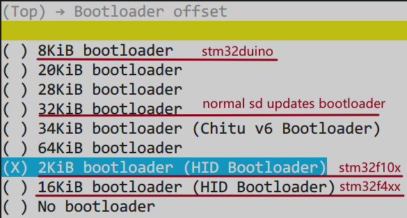
- 可知 f103c6t6 的 flash 很小,甚至如果使用常见的 sd卡升级bl,它占用32KB空间,根本没有余量给Klipper固件了。
- stm32duino-bootloader 占用 8KB,hid-bootloader 占用 2KB,肯定优选后者
- 那岂不是 No bootloader 更方便?但是烧录固件需要使用 3.3v serial,可以但没必要,除非你不怕麻烦
- klipper固件至少需要 16KB Flash 存储和 4KB SRAM 运存
As far as I know, the STM32F1 code is coded for 16K chips. Klipper itself can run on chips with as little as 1K of ram (though it really wants at least 4K). The flash size varies a bit depending on architecture, but it is typically around 16K in size. I don't know what the STM32F3 would require. I suspect supporting the STM32F3 would require code changes.
—— Source:Kevin
5、更多参考
关于 USB_DISC 以及 USB 设备枚举
其它

 萌萌哒新人
萌萌哒新人
 活跃会员
活跃会员
 宣传大使
宣传大使
 版主限定
版主限定
 牛X认证
牛X认证
 老版主限定
老版主限定
 创作达人
创作达人
 小蘑菇
小蘑菇
 编辑选择奖
编辑选择奖
 ARD DAY
 编辑选择奖
编辑选择奖
 摸鱼团员
摸鱼团员
 编辑选择奖
编辑选择奖
 志“童”道合
 编辑选择奖
编辑选择奖
 编辑选择奖
编辑选择奖
 编辑选择奖
编辑选择奖


 沪公网安备31011502402448
 置顶卡
置顶卡 变色卡
变色卡 千斤顶
千斤顶