主程序
- //Project Start: 1/6/2020
- //Last Updated: 7/29/2022
- //Version: Beta 1.3
-
- //========================================================================================================================//
-
- //CREDITS + SPECIAL THANKS
- /*
- Some elements inspired by:
- http://www.brokking.net/ymfc-32_main.html
-
- Madgwick filter function adapted from:
- https://github.com/arduino-libraries/MadgwickAHRS
-
- MPU9250 implementation based on MPU9250 library by:
- brian.taylor@bolderflight.com
- http://www.bolderflight.com
-
- Thank you to:
- RcGroups 'jihlein' - IMU implementation overhaul + SBUS implementation.
- Everyone that sends me pictures and videos of your flying creations! -Nick
-
- */
-
-
-
- //========================================================================================================================//
- // USER-SPECIFIED DEFINES //
- //========================================================================================================================//
-
- //Uncomment only one receiver type
- //#define USE_PWM_RX
- //#define USE_PPM_RX
- #define USE_SBUS_RX
- //#define USE_DSM_RX
- static const uint8_t num_DSM_channels = 16; //If using DSM RX, change this to match the number of transmitter channels you have
-
- //Uncomment only one IMU
- #define USE_MPU6050_I2C //Default
- //#define USE_MPU9250_SPI
-
- //Uncomment only one full scale gyro range (deg/sec)
- #define GYRO_250DPS //Default
- //#define GYRO_500DPS
- //#define GYRO_1000DPS
- //#define GYRO_2000DPS
-
- //Uncomment only one full scale accelerometer range (G's)
- #define ACCEL_2G //Default
- //#define ACCEL_4G
- //#define ACCEL_8G
- //#define ACCEL_16G
-
-
-
- //========================================================================================================================//
-
-
-
- //REQUIRED LIBRARIES (included with download in main sketch folder)
-
- #include <Wire.h> //I2c communication
- #include <SPI.h> //SPI communication
- #include <PWMServo.h> //Commanding any extra actuators, installed with teensyduino installer
- #include <FastLED.h>
-
- #if defined USE_SBUS_RX
- #include "src/SBUS/SBUS.h" //sBus interface
- #endif
-
- #if defined USE_DSM_RX
- #include "src/DSMRX/DSMRX.h"
- #endif
-
- #if defined USE_MPU6050_I2C
- #include "src/MPU6050/MPU6050.h"
- MPU6050 mpu6050;
- #elif defined USE_MPU9250_SPI
- #include "src/MPU9250/MPU9250.h"
- MPU9250 mpu9250(SPI2,36);
- #else
- #error No MPU defined...
- #endif
-
-
-
- //========================================================================================================================//
-
-
-
- //Setup gyro and accel full scale value selection and scale factor
-
- #if defined USE_MPU6050_I2C
- #define GYRO_FS_SEL_250 MPU6050_GYRO_FS_250
- #define GYRO_FS_SEL_500 MPU6050_GYRO_FS_500
- #define GYRO_FS_SEL_1000 MPU6050_GYRO_FS_1000
- #define GYRO_FS_SEL_2000 MPU6050_GYRO_FS_2000
- #define ACCEL_FS_SEL_2 MPU6050_ACCEL_FS_2
- #define ACCEL_FS_SEL_4 MPU6050_ACCEL_FS_4
- #define ACCEL_FS_SEL_8 MPU6050_ACCEL_FS_8
- #define ACCEL_FS_SEL_16 MPU6050_ACCEL_FS_16
- #elif defined USE_MPU9250_SPI
- #define GYRO_FS_SEL_250 mpu9250.GYRO_RANGE_250DPS
- #define GYRO_FS_SEL_500 mpu9250.GYRO_RANGE_500DPS
- #define GYRO_FS_SEL_1000 mpu9250.GYRO_RANGE_1000DPS
- #define GYRO_FS_SEL_2000 mpu9250.GYRO_RANGE_2000DPS
- #define ACCEL_FS_SEL_2 mpu9250.ACCEL_RANGE_2G
- #define ACCEL_FS_SEL_4 mpu9250.ACCEL_RANGE_4G
- #define ACCEL_FS_SEL_8 mpu9250.ACCEL_RANGE_8G
- #define ACCEL_FS_SEL_16 mpu9250.ACCEL_RANGE_16G
- #endif
-
- #if defined GYRO_250DPS
- #define GYRO_SCALE GYRO_FS_SEL_250
- #define GYRO_SCALE_FACTOR 131.0
- #elif defined GYRO_500DPS
- #define GYRO_SCALE GYRO_FS_SEL_500
- #define GYRO_SCALE_FACTOR 65.5
- #elif defined GYRO_1000DPS
- #define GYRO_SCALE GYRO_FS_SEL_1000
- #define GYRO_SCALE_FACTOR 32.8
- #elif defined GYRO_2000DPS
- #define GYRO_SCALE GYRO_FS_SEL_2000
- #define GYRO_SCALE_FACTOR 16.4
- #endif
-
- #if defined ACCEL_2G
- #define ACCEL_SCALE ACCEL_FS_SEL_2
- #define ACCEL_SCALE_FACTOR 16384.0
- #elif defined ACCEL_4G
- #define ACCEL_SCALE ACCEL_FS_SEL_4
- #define ACCEL_SCALE_FACTOR 8192.0
- #elif defined ACCEL_8G
- #define ACCEL_SCALE ACCEL_FS_SEL_8
- #define ACCEL_SCALE_FACTOR 4096.0
- #elif defined ACCEL_16G
- #define ACCEL_SCALE ACCEL_FS_SEL_16
- #define ACCEL_SCALE_FACTOR 2048.0
- #endif
-
-
-
-
- #define LED_PIN 12 // Pin connected to the LED strip
- #define NUM_LEDS 1 // Number of LEDs in the strip
- CRGB leds[NUM_LEDS];
-
- //========================================================================================================================//
- // USER-SPECIFIED VARIABLES //
- //========================================================================================================================//
-
- //Radio failsafe values for every channel in the event that bad reciever data is detected. Recommended defaults:
- unsigned long channel_1_fs = 1000; //thro
- unsigned long channel_2_fs = 1000; //ail
- unsigned long channel_3_fs = 1000; //elev
- unsigned long channel_4_fs = 1000; //rudd
- unsigned long channel_5_fs = 1500; //gear, greater than 1500 = throttle cut
- unsigned long channel_6_fs = 1500; //aux1
-
- unsigned long mode_1_servo_1 = 177; //Servo 1 Mode 1 Value
- unsigned long mode_1_servo_2 = 180; //Servo 2 Mode 1 Value
-
- unsigned long mode_2_servo_1 = 2; //Servo 1 Mode 2 Value
- unsigned long mode_2_servo_2 = 2; //Servo 2 Mode 2 Value
-
- unsigned long mode_3_servo_1 = 2; //Servo 1 Mode 3 Value
- unsigned long mode_3_servo_2 = 2; //Servo 2 Mode 3 Value
-
-
- int mode=0; //Mode 1 = Driving Mode 2 = Landed Mode 3 = Flying
-
- //Filter parameters - Defaults tuned for 2kHz loop rate; Do not touch unless you know what you are doing:
- float B_madgwick = 0.04; //Madgwick filter parameter
- float B_accel = 0.14; //Accelerometer LP filter paramter, (MPU6050 default: 0.14. MPU9250 default: 0.2)
- float B_gyro = 0.1; //Gyro LP filter paramter, (MPU6050 default: 0.1. MPU9250 default: 0.17)
- float B_mag = 1.0; //Magnetometer LP filter parameter
-
- //Magnetometer calibration parameters - if using MPU9250, uncomment calibrateMagnetometer() in void setup() to get these values, else just ignore these
- float MagErrorX = 0.0;
- float MagErrorY = 0.0;
- float MagErrorZ = 0.0;
- float MagScaleX = 1.0;
- float MagScaleY = 1.0;
- float MagScaleZ = 1.0;
-
- //IMU calibration parameters - calibrate IMU using calculate_IMU_error() in the void setup() to get these values, then comment out calculate_IMU_error()
- float AccErrorX = 0.04;
- float AccErrorY = -0.05;
- float AccErrorZ = -0.04;
- float GyroErrorX = -3.76;
- float GyroErrorY = 0.66;
- float GyroErrorZ = -0.02;
-
-
-
- //Controller parameters (take note of defaults before modifying!):
- float i_limit = 25.0; //Integrator saturation level, mostly for safety (default 25.0)
- float maxRoll = 30.0; //Max roll angle in degrees for angle mode (maximum ~70 degrees), deg/sec for rate mode
- float maxPitch = 30.0; //Max pitch angle in degrees for angle mode (maximum ~70 degrees), deg/sec for rate mode
- float maxYaw = 160.0; //Max yaw rate in deg/sec
-
- float Kp_roll_angle = 0.3; //Roll P-gain - angle mode
- float Ki_roll_angle = 0.0; //Roll I-gain - angle mode
- float Kd_roll_angle = 0.05; //Roll D-gain - angle mode (has no effect on controlANGLE2)
- float B_loop_roll = 0.9; //Roll damping term for controlANGLE2(), lower is more damping (must be between 0 to 1)
- float Kp_pitch_angle = 0.3; //Pitch P-gain - angle mode
- float Ki_pitch_angle = 0.0; //Pitch I-gain - angle mode
- float Kd_pitch_angle = 0.05; //Pitch D-gain - angle mode (has no effect on controlANGLE2)
- float B_loop_pitch = 0.9; //Pitch damping term for controlANGLE2(), lower is more damping (must be between 0 to 1)
-
- float Kp_roll_rate = 0.15; //Roll P-gain - rate mode
- float Ki_roll_rate = 0.2; //Roll I-gain - rate mode
- float Kd_roll_rate = 0.0002; //Roll D-gain - rate mode (be careful when increasing too high, motors will begin to overheat!)
- float Kp_pitch_rate = 0.15; //Pitch P-gain - rate mode
- float Ki_pitch_rate = 0.2; //Pitch I-gain - rate mode
- float Kd_pitch_rate = 0.0002; //Pitch D-gain - rate mode (be careful when increasing too high, motors will begin to overheat!)
-
- float Kp_yaw = 0.5; //Yaw P-gain
- float Ki_yaw = 0.05; //Yaw I-gain
- float Kd_yaw = 0.00015; //Yaw D-gain (be careful when increasing too high, motors will begin to overheat!)
-
-
-
- //========================================================================================================================//
- // DECLARE PINS //
- //========================================================================================================================//
-
- //NOTE: Pin 13 is reserved for onboard LED, pins 18 and 19 are reserved for the MPU6050 IMU for default setup
- //Radio:
- //Note: If using SBUS, connect to pin 21 (RX5), if using DSM, connect to pin 15 (RX3)
- const int ch1Pin = 15; //throttle
- const int ch2Pin = 16; //ail
- const int ch3Pin = 17; //ele
- const int ch4Pin = 20; //rudd
- const int ch5Pin = 21; //gear (throttle cut)
- const int ch6Pin = 22; //aux1 (free aux channel)
- const int PPM_Pin = 23;
- //OneShot125 ESC pin outputs:
- const int m1Pin = 0;
- const int m2Pin = 1;
- const int m3Pin = 2;
- const int m4Pin = 3;
- const int m5Pin = 4;
- const int m6Pin = 5;
- //PWM servo or ESC outputs:
- const int servo1Pin = 6; // Front Servo
- const int servo2Pin = 7; // Aft Servo
- const int servo3Pin = 8; // Linear Actuator 1 Signal 1
- const int servo4Pin = 9; // Linear Actuatot 1 Signal 2
- const int servo5Pin = 10; // Linear Actuator 2 Signal 1
- const int servo6Pin = 11; // Linear Actuatot 2 Signal 2
- const int servo7Pin = 12;
- PWMServo servo1; //Create servo objects to control a servo or ESC with PWM
- PWMServo servo2;
- PWMServo servo3;
- PWMServo servo4;
- PWMServo servo5;
- PWMServo servo6;
- //PWMServo servo7;
-
-
-
- //========================================================================================================================//
-
-
-
- //DECLARE GLOBAL VARIABLES
-
- //General stuff
- float dt;
- unsigned long current_time, prev_time;
- unsigned long print_counter, serial_counter;
- unsigned long blink_counter, blink_delay;
- bool blinkAlternate;
-
- //Radio communication:
- unsigned long channel_1_pwm, channel_2_pwm, channel_3_pwm, channel_4_pwm, channel_5_pwm, channel_6_pwm;
- unsigned long channel_1_pwm_prev, channel_2_pwm_prev, channel_3_pwm_prev, channel_4_pwm_prev;
-
- #if defined USE_SBUS_RX
- SBUS sbus(Serial5);
- uint16_t sbusChannels[16];
- bool sbusFailSafe;
- bool sbusLostFrame;
- #endif
- #if defined USE_DSM_RX
- DSM1024 DSM;
- #endif
-
- //IMU:
- float AccX, AccY, AccZ;
- float AccX_prev, AccY_prev, AccZ_prev;
- float GyroX, GyroY, GyroZ;
- float GyroX_prev, GyroY_prev, GyroZ_prev;
- float MagX, MagY, MagZ;
- float MagX_prev, MagY_prev, MagZ_prev;
- float roll_IMU, pitch_IMU, yaw_IMU;
- float roll_IMU_prev, pitch_IMU_prev;
- float q0 = 1.0f; //Initialize quaternion for madgwick filter
- float q1 = 0.0f;
- float q2 = 0.0f;
- float q3 = 0.0f;
-
- //Normalized desired state:
- float thro_des, roll_des, pitch_des, yaw_des;
- float roll_passthru, pitch_passthru, yaw_passthru;
-
- //Controller:
- float error_roll, error_roll_prev, roll_des_prev, integral_roll, integral_roll_il, integral_roll_ol, integral_roll_prev, integral_roll_prev_il, integral_roll_prev_ol, derivative_roll, roll_PID = 0;
- float error_pitch, error_pitch_prev, pitch_des_prev, integral_pitch, integral_pitch_il, integral_pitch_ol, integral_pitch_prev, integral_pitch_prev_il, integral_pitch_prev_ol, derivative_pitch, pitch_PID = 0;
- float error_yaw, error_yaw_prev, integral_yaw, integral_yaw_prev, derivative_yaw, yaw_PID = 0;
-
- //Mixer
- float m1_command_scaled, m2_command_scaled, m3_command_scaled, m4_command_scaled, m5_command_scaled, m6_command_scaled;
- int m1_command_PWM, m2_command_PWM, m3_command_PWM, m4_command_PWM, m5_command_PWM, m6_command_PWM;
- float s1_command_scaled, s2_command_scaled, s3_command_scaled, s4_command_scaled, s5_command_scaled, s6_command_scaled, s7_command_scaled;
- int s1_command_PWM, s2_command_PWM, s3_command_PWM, s4_command_PWM, s5_command_PWM, s6_command_PWM, s7_command_PWM;
-
- //Flight status
- bool armedFly = false;
-
- //========================================================================================================================//
- // VOID SETUP //
- //========================================================================================================================//
-
- void setup() {
- Serial.begin(500000); //USB serial
- delay(500);
-
- //Initialize all pins
- pinMode(13, OUTPUT); //Pin 13 LED blinker on board, do not modify
- pinMode(m1Pin, OUTPUT);
- pinMode(m2Pin, OUTPUT);
- pinMode(m3Pin, OUTPUT);
- pinMode(m4Pin, OUTPUT);
- pinMode(m5Pin, OUTPUT);
- pinMode(m6Pin, OUTPUT);
- servo1.attach(servo1Pin, 760, 2400); //Pin, min PWM value, max PWM value
- servo2.attach(servo2Pin, 900, 2030);
- servo3.attach(servo3Pin, 900, 2100);
- servo4.attach(servo4Pin, 900, 2100);
- servo5.attach(servo5Pin, 900, 2100);
- servo6.attach(servo6Pin, 900, 2100);
- //servo7.attach(servo7Pin, 900, 2100);
-
- FastLED.addLeds<WS2812, LED_PIN, GRB>(leds, NUM_LEDS);
- FastLED.clear(); // Ensure strip starts off
- FastLED.show();
- //Set built in LED to turn on to signal startup
- digitalWrite(13, HIGH);
-
- delay(5);
-
- //Initialize radio communication
- radioSetup();
-
- //Set radio channels to default (safe) values before entering main loop
- channel_1_pwm = channel_1_fs;
- channel_2_pwm = channel_2_fs;
- channel_3_pwm = channel_3_fs;
- channel_4_pwm = channel_4_fs;
- channel_5_pwm = channel_5_fs;
- channel_6_pwm = channel_6_fs;
-
- //Initialize IMU communication
- IMUinit();
-
- delay(5);
-
- //Get IMU error to zero accelerometer and gyro readings, assuming vehicle is level when powered up
- //calculate_IMU_error(); //Calibration parameters printed to serial monitor. Paste these in the user specified variables section, then comment this out forever.
-
- //Arm servo channels
- servo1.write(0); //Command servo angle from 0-180 degrees (1000 to 2000 PWM)
- servo2.write(0); //Set these to 90 for servos if you do not want them to briefly max out on startup
- // servo3.write(0); //Keep these at 0 if you are using servo outputs for motors
- // servo4.write(0);
- // servo5.write(0);
- // servo6.write(0);
- // servo7.write(0);
- //
- delay(5);
-
- //calibrateESCs(); //PROPS OFF. Uncomment this to calibrate your ESCs by setting throttle stick to max, powering on, and lowering throttle to zero after the beeps
- //Code will not proceed past here if this function is uncommented!
-
- //Arm OneShot125 motors
- m1_command_PWM = 125; //Command OneShot125 ESC from 125 to 250us pulse length
- m2_command_PWM = 125;
- m3_command_PWM = 125;
- m4_command_PWM = 125;
- m5_command_PWM = 125;
- m6_command_PWM = 125;
- armMotors(); //Loop over commandMotors() until ESCs happily arm
-
- //Indicate entering main loop with 3 quick blinks
- setupBlink(3,160,70); //numBlinks, upTime (ms), downTime (ms)
-
- //If using MPU9250 IMU, uncomment for one-time magnetometer calibration (may need to repeat for new locations)
- //calibrateMagnetometer(); //Generates magentometer error and scale factors to be pasted in user-specified variables section
-
- }
-
-
-
- //========================================================================================================================//
- // MAIN LOOP //
- //========================================================================================================================//
-
- void loop() {
- //Keep track of what time it is and how much time has elapsed since the last loop
- prev_time = current_time;
- current_time = micros();
- dt = (current_time - prev_time)/1000000.0;
-
- loopBlink(); //Indicate we are in main loop with short blink every 1.5 seconds
-
- //Print data at 100hz (uncomment one at a time for troubleshooting) - SELECT ONE:
- //printRadioData(); //Prints radio pwm values (expected: 1000 to 2000)
- //printDesiredState(); //Prints desired vehicle state commanded in either degrees or deg/sec (expected: +/- maxAXIS for roll, pitch, yaw; 0 to 1 for throttle)
- //printGyroData(); //Prints filtered gyro data direct from IMU (expected: ~ -250 to 250, 0 at rest)
- //printAccelData(); //Prints filtered accelerometer data direct from IMU (expected: ~ -2 to 2; x,y 0 when level, z 1 when level)
- //printMagData(); //Prints filtered magnetometer data direct from IMU (expected: ~ -300 to 300)
- //printRollPitchYaw(); //Prints roll, pitch, and yaw angles in degrees from Madgwick filter (expected: degrees, 0 when level)
- //printPIDoutput(); //Prints computed stabilized PID variables from controller and desired setpoint (expected: ~ -1 to 1)
- //printMotorCommands(); //Prints the values being written to the motors (expected: 120 to 250)
- //printServoCommands(); //Prints the values being written to the servos (expected: 0 to 180)
- //printLoopRate(); //Prints the time between loops in microseconds (expected: microseconds between loop iterations)
-
- // Get arming status
- armedStatus(); //Check if the throttle cut is off and throttle is low.
-
- //Get vehicle state
- getIMUdata(); //Pulls raw gyro, accelerometer, and magnetometer data from IMU and LP filters to remove noise
- Madgwick(GyroX, -GyroY, -GyroZ, -AccX, AccY, AccZ, MagY, -MagX, MagZ, dt); //Updates roll_IMU, pitch_IMU, and yaw_IMU angle estimates (degrees)
-
- //Compute desired state
- getDesState(); //Convert raw commands to normalized values based on saturated control limits
-
- //PID Controller - SELECT ONE:
- controlANGLE(); //Stabilize on angle setpoint
- //controlANGLE2(); //Stabilize on angle setpoint using cascaded method. Rate controller must be tuned well first!
- //controlRATE(); //Stabilize on rate setpoint
-
- //Actuator mixing and scaling to PWM values
- controlMixer(); //Mixes PID outputs to scaled actuator commands -- custom mixing assignments done here
- modeControl();
- scaleCommands(); //Scales motor commands to 125 to 250 range (oneshot125 protocol) and servo PWM commands to 0 to 180 (for servo library)
-
- //Throttle cut check
- throttleCut(); //Directly sets motor commands to low based on state of ch5
-
- //Command actuators
- commandMotors(); //Sends command pulses to each motor pin using OneShot125 protocol
- servo1.write(s1_command_PWM); // Front Lifting Servo//Writes PWM value to servo object
- servo2.write(s2_command_PWM); // Aft Lifting Servo
- //servo3.write(s3_command_PWM);
- //servo4.write(s4_command_PWM);
- //servo5.write(s5_command_PWM);
- //servo6.write(s6_command_PWM);
- //servo7.write(s7_command_PWM);
-
- //Get vehicle commands for next loop iteration
- getCommands(); //Pulls current available radio commands
- failSafe(); //Prevent failures in event of bad receiver connection, defaults to failsafe values assigned in setup
-
- //Regulate loop rate
- loopRate(2000); //Do not exceed 2000Hz, all filter parameters tuned to 2000Hz by default
- }
-
-
-
- //========================================================================================================================//
- // FUNCTIONS //
- //========================================================================================================================//
-
- void modeControl(){
-
- if (channel_6_pwm<1100){
- mode=1;
- }
- else if ((channel_6_pwm>1400) & (channel_6_pwm<1600)){
- mode=2;
- }
- else if (channel_6_pwm>1900){
- mode=3;
- }
- if (mode==0){
- mode=2;
- }
- else if(mode==1){
- digitalWrite(servo3Pin,LOW); //Actuator 1 Signal 1
- digitalWrite(servo4Pin,HIGH); //Actuator 1 Signal 1
-
- digitalWrite(servo5Pin,LOW); //Actuator 2 Signal 1
- digitalWrite(servo6Pin,HIGH); //Actuator 2 Signal 1
-
- s1_command_PWM=mode_1_servo_1;
- s2_command_PWM=mode_1_servo_2;
- m1_command_scaled=0;
- m2_command_scaled=0;
- m3_command_scaled=0;
- m4_command_scaled=0;
-
- leds[0] = CRGB(255, 255, 255);
-
- }
- else if(mode==2){
- digitalWrite(servo3Pin,LOW); //Actuator 1 Signal 1
- digitalWrite(servo4Pin,HIGH); //Actuator 1 Signal 1
-
- digitalWrite(servo5Pin,LOW); //Actuator 2 Signal 1
- digitalWrite(servo6Pin,HIGH); //Actuator 2 Signal 1
-
- s1_command_PWM=mode_2_servo_1;
- s2_command_PWM=mode_2_servo_2;
- m5_command_scaled=0.5;
- m6_command_scaled=0.5;
- m1_command_scaled=0;
- m2_command_scaled=0;
- m3_command_scaled=0;
- m4_command_scaled=0;
-
- leds[0] = CRGB(1, 1, 255);
- }
- else if(mode==3){
- digitalWrite(servo3Pin,HIGH); //Actuator 1 Signal 1
- digitalWrite(servo4Pin,LOW); //Actuator 1 Signal 1
-
- digitalWrite(servo5Pin,HIGH); //Actuator 2 Signal 1
- digitalWrite(servo6Pin,LOW); //Actuator 2 Signal 1
-
- s1_command_PWM=mode_3_servo_1;
- s2_command_PWM=mode_3_servo_2;
- m5_command_scaled=0.5;
- m6_command_scaled=0.5;
-
- leds[0] = CRGB(255, 255, 255);
-
- }
-
- FastLED.show();
-
-
- }
-
-
- void controlMixer() {
- //DESCRIPTION: Mixes scaled commands from PID controller to actuator outputs based on vehicle configuration
- /*
- * Takes roll_PID, pitch_PID, and yaw_PID computed from the PID controller and appropriately mixes them for the desired
- * vehicle configuration. For example on a quadcopter, the left two motors should have +roll_PID while the right two motors
- * should have -roll_PID. Front two should have -pitch_PID and the back two should have +pitch_PID etc... every motor has
- * normalized (0 to 1) thro_des command for throttle control. Can also apply direct unstabilized commands from the transmitter with
- * roll_passthru, pitch_passthru, and yaw_passthu. mX_command_scaled and sX_command scaled variables are used in scaleCommands()
- * in preparation to be sent to the motor ESCs and servos.
- *
- *Relevant variables:
- *thro_des - direct thottle control
- *roll_PID, pitch_PID, yaw_PID - stabilized axis variables
- *roll_passthru, pitch_passthru, yaw_passthru - direct unstabilized command passthrough
- *channel_6_pwm - free auxillary channel, can be used to toggle things with an 'if' statement
- */
-
- //Quad mixing - EXAMPLE
- m1_command_scaled = thro_des - pitch_PID + roll_PID + yaw_PID; //Front Left
- m2_command_scaled = thro_des - pitch_PID - roll_PID - yaw_PID; //Front Right
- m3_command_scaled = thro_des + pitch_PID - roll_PID + yaw_PID; //Back Right
- m4_command_scaled = thro_des + pitch_PID + roll_PID - yaw_PID; //Back Left
-
- m5_command_scaled = ((float(channel_2_pwm-1000)/1000))-(((float(channel_1_pwm-1000)/1000))-0.5)*0.2;
- m6_command_scaled = ((float(channel_2_pwm-1000)/1000))+(((float(channel_1_pwm-1000)/1000))-0.5)*0.2;;
-
- if(abs(0.5-m5_command_scaled)<0.04){
- m5_command_scaled=0.5;
- }
- if(abs(0.5-m6_command_scaled)<0.04){
- m6_command_scaled=0.5;
- }
- //0.5 is centered servo, 0.0 is zero throttle if connecting to ESC for conventional PWM, 1.0 is max throttle
- //s1_command_scaled = 0;
- //s2_command_scaled = 0;
- //s3_command_scaled = 0;
- //s4_command_scaled = 0;
- //s5_command_scaled = 0;
- //s6_command_scaled = 0;
- //s7_command_scaled = 0;
-
- }
-
- void armedStatus() {
- //DESCRIPTION: Check if the throttle cut is off and the throttle input is low to prepare for flight.
- if ((channel_5_pwm > 1500) && (channel_3_pwm < 1050)) {
- armedFly = true;
- }
- }
-
- void IMUinit() {
- //DESCRIPTION: Initialize IMU
- /*
- * Don't worry about how this works.
- */
- #if defined USE_MPU6050_I2C
- Wire.begin();
- Wire.setClock(1000000); //Note this is 2.5 times the spec sheet 400 kHz max...
-
- mpu6050.initialize();
-
- if (mpu6050.testConnection() == false) {
- Serial.println("MPU6050 initialization unsuccessful");
- Serial.println("Check MPU6050 wiring or try cycling power");
- while(1) {}
- }
-
- //From the reset state all registers should be 0x00, so we should be at
- //max sample rate with digital low pass filter(s) off. All we need to
- //do is set the desired fullscale ranges
- mpu6050.setFullScaleGyroRange(GYRO_SCALE);
- mpu6050.setFullScaleAccelRange(ACCEL_SCALE);
-
- #elif defined USE_MPU9250_SPI
- int status = mpu9250.begin();
-
- if (status < 0) {
- Serial.println("MPU9250 initialization unsuccessful");
- Serial.println("Check MPU9250 wiring or try cycling power");
- Serial.print("Status: ");
- Serial.println(status);
- while(1) {}
- }
-
- //From the reset state all registers should be 0x00, so we should be at
- //max sample rate with digital low pass filter(s) off. All we need to
- //do is set the desired fullscale ranges
- mpu9250.setGyroRange(GYRO_SCALE);
- mpu9250.setAccelRange(ACCEL_SCALE);
- mpu9250.setMagCalX(MagErrorX, MagScaleX);
- mpu9250.setMagCalY(MagErrorY, MagScaleY);
- mpu9250.setMagCalZ(MagErrorZ, MagScaleZ);
- mpu9250.setSrd(0); //sets gyro and accel read to 1khz, magnetometer read to 100hz
- #endif
- }
-
- void getIMUdata() {
- //DESCRIPTION: Request full dataset from IMU and LP filter gyro, accelerometer, and magnetometer data
- /*
- * Reads accelerometer, gyro, and magnetometer data from IMU as AccX, AccY, AccZ, GyroX, GyroY, GyroZ, MagX, MagY, MagZ.
- * These values are scaled according to the IMU datasheet to put them into correct units of g's, deg/sec, and uT. A simple first-order
- * low-pass filter is used to get rid of high frequency noise in these raw signals. Generally you want to cut
- * off everything past 80Hz, but if your loop rate is not fast enough, the low pass filter will cause a lag in
- * the readings. The filter parameters B_gyro and B_accel are set to be good for a 2kHz loop rate. Finally,
- * the constant errors found in calculate_IMU_error() on startup are subtracted from the accelerometer and gyro readings.
- */
- int16_t AcX,AcY,AcZ,GyX,GyY,GyZ,MgX,MgY,MgZ;
-
- #if defined USE_MPU6050_I2C
- mpu6050.getMotion6(&AcX, &AcY, &AcZ, &GyX, &GyY, &GyZ);
- #elif defined USE_MPU9250_SPI
- mpu9250.getMotion9(&AcX, &AcY, &AcZ, &GyX, &GyY, &GyZ, &MgX, &MgY, &MgZ);
- #endif
-
- //Accelerometer
- AccX = AcX / ACCEL_SCALE_FACTOR; //G's
- AccY = AcY / ACCEL_SCALE_FACTOR;
- AccZ = AcZ / ACCEL_SCALE_FACTOR;
- //Correct the outputs with the calculated error values
- AccX = AccX - AccErrorX;
- AccY = AccY - AccErrorY;
- AccZ = AccZ - AccErrorZ;
- //LP filter accelerometer data
- AccX = (1.0 - B_accel)*AccX_prev + B_accel*AccX;
- AccY = (1.0 - B_accel)*AccY_prev + B_accel*AccY;
- AccZ = (1.0 - B_accel)*AccZ_prev + B_accel*AccZ;
- AccX_prev = AccX;
- AccY_prev = AccY;
- AccZ_prev = AccZ;
-
- //Gyro
- GyroX = GyX / GYRO_SCALE_FACTOR; //deg/sec
- GyroY = GyY / GYRO_SCALE_FACTOR;
- GyroZ = GyZ / GYRO_SCALE_FACTOR;
- //Correct the outputs with the calculated error values
- GyroX = GyroX - GyroErrorX;
- GyroY = GyroY - GyroErrorY;
- GyroZ = GyroZ - GyroErrorZ;
- //LP filter gyro data
- GyroX = (1.0 - B_gyro)*GyroX_prev + B_gyro*GyroX;
- GyroY = (1.0 - B_gyro)*GyroY_prev + B_gyro*GyroY;
- GyroZ = (1.0 - B_gyro)*GyroZ_prev + B_gyro*GyroZ;
- GyroX_prev = GyroX;
- GyroY_prev = GyroY;
- GyroZ_prev = GyroZ;
-
- //Magnetometer
- MagX = MgX/6.0; //uT
- MagY = MgY/6.0;
- MagZ = MgZ/6.0;
- //Correct the outputs with the calculated error values
- MagX = (MagX - MagErrorX)*MagScaleX;
- MagY = (MagY - MagErrorY)*MagScaleY;
- MagZ = (MagZ - MagErrorZ)*MagScaleZ;
- //LP filter magnetometer data
- MagX = (1.0 - B_mag)*MagX_prev + B_mag*MagX;
- MagY = (1.0 - B_mag)*MagY_prev + B_mag*MagY;
- MagZ = (1.0 - B_mag)*MagZ_prev + B_mag*MagZ;
- MagX_prev = MagX;
- MagY_prev = MagY;
- MagZ_prev = MagZ;
- }
-
- void calculate_IMU_error() {
- //DESCRIPTION: Computes IMU accelerometer and gyro error on startup. Note: vehicle should be powered up on flat surface
- /*
- * Don't worry too much about what this is doing. The error values it computes are applied to the raw gyro and
- * accelerometer values AccX, AccY, AccZ, GyroX, GyroY, GyroZ in getIMUdata(). This eliminates drift in the
- * measurement.
- */
- int16_t AcX,AcY,AcZ,GyX,GyY,GyZ,MgX,MgY,MgZ;
- AccErrorX = 0.0;
- AccErrorY = 0.0;
- AccErrorZ = 0.0;
- GyroErrorX = 0.0;
- GyroErrorY= 0.0;
- GyroErrorZ = 0.0;
-
- //Read IMU values 12000 times
- int c = 0;
- while (c < 12000) {
- #if defined USE_MPU6050_I2C
- mpu6050.getMotion6(&AcX, &AcY, &AcZ, &GyX, &GyY, &GyZ);
- #elif defined USE_MPU9250_SPI
- mpu9250.getMotion9(&AcX, &AcY, &AcZ, &GyX, &GyY, &GyZ, &MgX, &MgY, &MgZ);
- #endif
-
- AccX = AcX / ACCEL_SCALE_FACTOR;
- AccY = AcY / ACCEL_SCALE_FACTOR;
- AccZ = AcZ / ACCEL_SCALE_FACTOR;
- GyroX = GyX / GYRO_SCALE_FACTOR;
- GyroY = GyY / GYRO_SCALE_FACTOR;
- GyroZ = GyZ / GYRO_SCALE_FACTOR;
-
- //Sum all readings
- AccErrorX = AccErrorX + AccX;
- AccErrorY = AccErrorY + AccY;
- AccErrorZ = AccErrorZ + AccZ;
- GyroErrorX = GyroErrorX + GyroX;
- GyroErrorY = GyroErrorY + GyroY;
- GyroErrorZ = GyroErrorZ + GyroZ;
- c++;
- }
- //Divide the sum by 12000 to get the error value
- AccErrorX = AccErrorX / c;
- AccErrorY = AccErrorY / c;
- AccErrorZ = AccErrorZ / c - 1.0;
- GyroErrorX = GyroErrorX / c;
- GyroErrorY = GyroErrorY / c;
- GyroErrorZ = GyroErrorZ / c;
-
- Serial.print("float AccErrorX = ");
- Serial.print(AccErrorX);
- Serial.println(";");
- Serial.print("float AccErrorY = ");
- Serial.print(AccErrorY);
- Serial.println(";");
- Serial.print("float AccErrorZ = ");
- Serial.print(AccErrorZ);
- Serial.println(";");
-
- Serial.print("float GyroErrorX = ");
- Serial.print(GyroErrorX);
- Serial.println(";");
- Serial.print("float GyroErrorY = ");
- Serial.print(GyroErrorY);
- Serial.println(";");
- Serial.print("float GyroErrorZ = ");
- Serial.print(GyroErrorZ);
- Serial.println(";");
-
- Serial.println("Paste these values in user specified variables section and comment out calculate_IMU_error() in void setup.");
- }
-
- void calibrateAttitude() {
- //DESCRIPTION: Used to warm up the main loop to allow the madwick filter to converge before commands can be sent to the actuators
- //Assuming vehicle is powered up on level surface!
- /*
- * This function is used on startup to warm up the attitude estimation and is what causes startup to take a few seconds
- * to boot.
- */
- //Warm up IMU and madgwick filter in simulated main loop
- for (int i = 0; i <= 10000; i++) {
- prev_time = current_time;
- current_time = micros();
- dt = (current_time - prev_time)/1000000.0;
- getIMUdata();
- Madgwick(GyroX, -GyroY, -GyroZ, -AccX, AccY, AccZ, MagY, -MagX, MagZ, dt);
- loopRate(2000); //do not exceed 2000Hz
- }
- }
-
- void Madgwick(float gx, float gy, float gz, float ax, float ay, float az, float mx, float my, float mz, float invSampleFreq) {
- //DESCRIPTION: Attitude estimation through sensor fusion - 9DOF
- /*
- * This function fuses the accelerometer gyro, and magnetometer readings AccX, AccY, AccZ, GyroX, GyroY, GyroZ, MagX, MagY, and MagZ for attitude estimation.
- * Don't worry about the math. There is a tunable parameter B_madgwick in the user specified variable section which basically
- * adjusts the weight of gyro data in the state estimate. Higher beta leads to noisier estimate, lower
- * beta leads to slower to respond estimate. It is currently tuned for 2kHz loop rate. This function updates the roll_IMU,
- * pitch_IMU, and yaw_IMU variables which are in degrees. If magnetometer data is not available, this function calls Madgwick6DOF() instead.
- */
- float recipNorm;
- float s0, s1, s2, s3;
- float qDot1, qDot2, qDot3, qDot4;
- float hx, hy;
- float _2q0mx, _2q0my, _2q0mz, _2q1mx, _2bx, _2bz, _4bx, _4bz, _2q0, _2q1, _2q2, _2q3, _2q0q2, _2q2q3, q0q0, q0q1, q0q2, q0q3, q1q1, q1q2, q1q3, q2q2, q2q3, q3q3;
-
- //use 6DOF algorithm if MPU6050 is being used
- #if defined USE_MPU6050_I2C
- Madgwick6DOF(gx, gy, gz, ax, ay, az, invSampleFreq);
- return;
- #endif
-
- //Use 6DOF algorithm if magnetometer measurement invalid (avoids NaN in magnetometer normalisation)
- if((mx == 0.0f) && (my == 0.0f) && (mz == 0.0f)) {
- Madgwick6DOF(gx, gy, gz, ax, ay, az, invSampleFreq);
- return;
- }
-
- //Convert gyroscope degrees/sec to radians/sec
- gx *= 0.0174533f;
- gy *= 0.0174533f;
- gz *= 0.0174533f;
-
- //Rate of change of quaternion from gyroscope
- qDot1 = 0.5f * (-q1 * gx - q2 * gy - q3 * gz);
- qDot2 = 0.5f * (q0 * gx + q2 * gz - q3 * gy);
- qDot3 = 0.5f * (q0 * gy - q1 * gz + q3 * gx);
- qDot4 = 0.5f * (q0 * gz + q1 * gy - q2 * gx);
-
- //Compute feedback only if accelerometer measurement valid (avoids NaN in accelerometer normalisation)
- if(!((ax == 0.0f) && (ay == 0.0f) && (az == 0.0f))) {
-
- //Normalise accelerometer measurement
- recipNorm = invSqrt(ax * ax + ay * ay + az * az);
- ax *= recipNorm;
- ay *= recipNorm;
- az *= recipNorm;
-
- //Normalise magnetometer measurement
- recipNorm = invSqrt(mx * mx + my * my + mz * mz);
- mx *= recipNorm;
- my *= recipNorm;
- mz *= recipNorm;
-
- //Auxiliary variables to avoid repeated arithmetic
- _2q0mx = 2.0f * q0 * mx;
- _2q0my = 2.0f * q0 * my;
- _2q0mz = 2.0f * q0 * mz;
- _2q1mx = 2.0f * q1 * mx;
- _2q0 = 2.0f * q0;
- _2q1 = 2.0f * q1;
- _2q2 = 2.0f * q2;
- _2q3 = 2.0f * q3;
- _2q0q2 = 2.0f * q0 * q2;
- _2q2q3 = 2.0f * q2 * q3;
- q0q0 = q0 * q0;
- q0q1 = q0 * q1;
- q0q2 = q0 * q2;
- q0q3 = q0 * q3;
- q1q1 = q1 * q1;
- q1q2 = q1 * q2;
- q1q3 = q1 * q3;
- q2q2 = q2 * q2;
- q2q3 = q2 * q3;
- q3q3 = q3 * q3;
-
- //Reference direction of Earth's magnetic field
- hx = mx * q0q0 - _2q0my * q3 + _2q0mz * q2 + mx * q1q1 + _2q1 * my * q2 + _2q1 * mz * q3 - mx * q2q2 - mx * q3q3;
- hy = _2q0mx * q3 + my * q0q0 - _2q0mz * q1 + _2q1mx * q2 - my * q1q1 + my * q2q2 + _2q2 * mz * q3 - my * q3q3;
- _2bx = sqrtf(hx * hx + hy * hy);
- _2bz = -_2q0mx * q2 + _2q0my * q1 + mz * q0q0 + _2q1mx * q3 - mz * q1q1 + _2q2 * my * q3 - mz * q2q2 + mz * q3q3;
- _4bx = 2.0f * _2bx;
- _4bz = 2.0f * _2bz;
-
- //Gradient decent algorithm corrective step
- s0 = -_2q2 * (2.0f * q1q3 - _2q0q2 - ax) + _2q1 * (2.0f * q0q1 + _2q2q3 - ay) - _2bz * q2 * (_2bx * (0.5f - q2q2 - q3q3) + _2bz * (q1q3 - q0q2) - mx) + (-_2bx * q3 + _2bz * q1) * (_2bx * (q1q2 - q0q3) + _2bz * (q0q1 + q2q3) - my) + _2bx * q2 * (_2bx * (q0q2 + q1q3) + _2bz * (0.5f - q1q1 - q2q2) - mz);
- s1 = _2q3 * (2.0f * q1q3 - _2q0q2 - ax) + _2q0 * (2.0f * q0q1 + _2q2q3 - ay) - 4.0f * q1 * (1 - 2.0f * q1q1 - 2.0f * q2q2 - az) + _2bz * q3 * (_2bx * (0.5f - q2q2 - q3q3) + _2bz * (q1q3 - q0q2) - mx) + (_2bx * q2 + _2bz * q0) * (_2bx * (q1q2 - q0q3) + _2bz * (q0q1 + q2q3) - my) + (_2bx * q3 - _4bz * q1) * (_2bx * (q0q2 + q1q3) + _2bz * (0.5f - q1q1 - q2q2) - mz);
- s2 = -_2q0 * (2.0f * q1q3 - _2q0q2 - ax) + _2q3 * (2.0f * q0q1 + _2q2q3 - ay) - 4.0f * q2 * (1 - 2.0f * q1q1 - 2.0f * q2q2 - az) + (-_4bx * q2 - _2bz * q0) * (_2bx * (0.5f - q2q2 - q3q3) + _2bz * (q1q3 - q0q2) - mx) + (_2bx * q1 + _2bz * q3) * (_2bx * (q1q2 - q0q3) + _2bz * (q0q1 + q2q3) - my) + (_2bx * q0 - _4bz * q2) * (_2bx * (q0q2 + q1q3) + _2bz * (0.5f - q1q1 - q2q2) - mz);
- s3 = _2q1 * (2.0f * q1q3 - _2q0q2 - ax) + _2q2 * (2.0f * q0q1 + _2q2q3 - ay) + (-_4bx * q3 + _2bz * q1) * (_2bx * (0.5f - q2q2 - q3q3) + _2bz * (q1q3 - q0q2) - mx) + (-_2bx * q0 + _2bz * q2) * (_2bx * (q1q2 - q0q3) + _2bz * (q0q1 + q2q3) - my) + _2bx * q1 * (_2bx * (q0q2 + q1q3) + _2bz * (0.5f - q1q1 - q2q2) - mz);
- recipNorm = invSqrt(s0 * s0 + s1 * s1 + s2 * s2 + s3 * s3); // normalise step magnitude
- s0 *= recipNorm;
- s1 *= recipNorm;
- s2 *= recipNorm;
- s3 *= recipNorm;
-
- //Apply feedback step
- qDot1 -= B_madgwick * s0;
- qDot2 -= B_madgwick * s1;
- qDot3 -= B_madgwick * s2;
- qDot4 -= B_madgwick * s3;
- }
-
- //Integrate rate of change of quaternion to yield quaternion
- q0 += qDot1 * invSampleFreq;
- q1 += qDot2 * invSampleFreq;
- q2 += qDot3 * invSampleFreq;
- q3 += qDot4 * invSampleFreq;
-
- //Normalize quaternion
- recipNorm = invSqrt(q0 * q0 + q1 * q1 + q2 * q2 + q3 * q3);
- q0 *= recipNorm;
- q1 *= recipNorm;
- q2 *= recipNorm;
- q3 *= recipNorm;
-
- //compute angles - NWU
- roll_IMU = atan2(q0*q1 + q2*q3, 0.5f - q1*q1 - q2*q2)*57.29577951; //degrees
- pitch_IMU = -asin(constrain(-2.0f * (q1*q3 - q0*q2),-0.999999,0.999999))*57.29577951; //degrees
- yaw_IMU = -atan2(q1*q2 + q0*q3, 0.5f - q2*q2 - q3*q3)*57.29577951; //degrees
- }
-
- void Madgwick6DOF(float gx, float gy, float gz, float ax, float ay, float az, float invSampleFreq) {
- //DESCRIPTION: Attitude estimation through sensor fusion - 6DOF
- /*
- * See description of Madgwick() for more information. This is a 6DOF implimentation for when magnetometer data is not
- * available (for example when using the recommended MPU6050 IMU for the default setup).
- */
- float recipNorm;
- float s0, s1, s2, s3;
- float qDot1, qDot2, qDot3, qDot4;
- float _2q0, _2q1, _2q2, _2q3, _4q0, _4q1, _4q2 ,_8q1, _8q2, q0q0, q1q1, q2q2, q3q3;
-
- //Convert gyroscope degrees/sec to radians/sec
- gx *= 0.0174533f;
- gy *= 0.0174533f;
- gz *= 0.0174533f;
-
- //Rate of change of quaternion from gyroscope
- qDot1 = 0.5f * (-q1 * gx - q2 * gy - q3 * gz);
- qDot2 = 0.5f * (q0 * gx + q2 * gz - q3 * gy);
- qDot3 = 0.5f * (q0 * gy - q1 * gz + q3 * gx);
- qDot4 = 0.5f * (q0 * gz + q1 * gy - q2 * gx);
-
- //Compute feedback only if accelerometer measurement valid (avoids NaN in accelerometer normalisation)
- if(!((ax == 0.0f) && (ay == 0.0f) && (az == 0.0f))) {
- //Normalise accelerometer measurement
- recipNorm = invSqrt(ax * ax + ay * ay + az * az);
- ax *= recipNorm;
- ay *= recipNorm;
- az *= recipNorm;
-
- //Auxiliary variables to avoid repeated arithmetic
- _2q0 = 2.0f * q0;
- _2q1 = 2.0f * q1;
- _2q2 = 2.0f * q2;
- _2q3 = 2.0f * q3;
- _4q0 = 4.0f * q0;
- _4q1 = 4.0f * q1;
- _4q2 = 4.0f * q2;
- _8q1 = 8.0f * q1;
- _8q2 = 8.0f * q2;
- q0q0 = q0 * q0;
- q1q1 = q1 * q1;
- q2q2 = q2 * q2;
- q3q3 = q3 * q3;
-
- //Gradient decent algorithm corrective step
- s0 = _4q0 * q2q2 + _2q2 * ax + _4q0 * q1q1 - _2q1 * ay;
- s1 = _4q1 * q3q3 - _2q3 * ax + 4.0f * q0q0 * q1 - _2q0 * ay - _4q1 + _8q1 * q1q1 + _8q1 * q2q2 + _4q1 * az;
- s2 = 4.0f * q0q0 * q2 + _2q0 * ax + _4q2 * q3q3 - _2q3 * ay - _4q2 + _8q2 * q1q1 + _8q2 * q2q2 + _4q2 * az;
- s3 = 4.0f * q1q1 * q3 - _2q1 * ax + 4.0f * q2q2 * q3 - _2q2 * ay;
- recipNorm = invSqrt(s0 * s0 + s1 * s1 + s2 * s2 + s3 * s3); //normalise step magnitude
- s0 *= recipNorm;
- s1 *= recipNorm;
- s2 *= recipNorm;
- s3 *= recipNorm;
-
- //Apply feedback step
- qDot1 -= B_madgwick * s0;
- qDot2 -= B_madgwick * s1;
- qDot3 -= B_madgwick * s2;
- qDot4 -= B_madgwick * s3;
- }
-
- //Integrate rate of change of quaternion to yield quaternion
- q0 += qDot1 * invSampleFreq;
- q1 += qDot2 * invSampleFreq;
- q2 += qDot3 * invSampleFreq;
- q3 += qDot4 * invSampleFreq;
-
- //Normalise quaternion
- recipNorm = invSqrt(q0 * q0 + q1 * q1 + q2 * q2 + q3 * q3);
- q0 *= recipNorm;
- q1 *= recipNorm;
- q2 *= recipNorm;
- q3 *= recipNorm;
-
- //Compute angles
- roll_IMU = atan2(q0*q1 + q2*q3, 0.5f - q1*q1 - q2*q2)*57.29577951; //degrees
- pitch_IMU = -asin(constrain(-2.0f * (q1*q3 - q0*q2),-0.999999,0.999999))*57.29577951; //degrees
- yaw_IMU = -atan2(q1*q2 + q0*q3, 0.5f - q2*q2 - q3*q3)*57.29577951; //degrees
- }
-
- void getDesState() {
- //DESCRIPTION: Normalizes desired control values to appropriate values
- /*
- * Updates the desired state variables thro_des, roll_des, pitch_des, and yaw_des. These are computed by using the raw
- * RC pwm commands and scaling them to be within our limits defined in setup. thro_des stays within 0 to 1 range.
- * roll_des and pitch_des are scaled to be within max roll/pitch amount in either degrees (angle mode) or degrees/sec
- * (rate mode). yaw_des is scaled to be within max yaw in degrees/sec. Also creates roll_passthru, pitch_passthru, and
- * yaw_passthru variables, to be used in commanding motors/servos with direct unstabilized commands in controlMixer().
- */
- thro_des = (channel_3_pwm - 1000.0)/1000.0; //Between 0 and 1
- roll_des = (channel_1_pwm - 1500.0)/500.0; //Between -1 and 1
- pitch_des = (channel_2_pwm - 1500.0)/500.0; //Between -1 and 1
- yaw_des = (channel_4_pwm - 1500.0)/500.0; //Between -1 and 1
- roll_passthru = roll_des/2.0; //Between -0.5 and 0.5
- pitch_passthru = pitch_des/2.0; //Between -0.5 and 0.5
- yaw_passthru = yaw_des/2.0; //Between -0.5 and 0.5
-
- //Constrain within normalized bounds
- thro_des = constrain(thro_des, 0.0, 1.0); //Between 0 and 1
- roll_des = constrain(roll_des, -1.0, 1.0)*maxRoll; //Between -maxRoll and +maxRoll
- pitch_des = constrain(pitch_des, -1.0, 1.0)*maxPitch; //Between -maxPitch and +maxPitch
- yaw_des = constrain(yaw_des, -1.0, 1.0)*maxYaw; //Between -maxYaw and +maxYaw
- roll_passthru = constrain(roll_passthru, -0.5, 0.5);
- pitch_passthru = constrain(pitch_passthru, -0.5, 0.5);
- yaw_passthru = constrain(yaw_passthru, -0.5, 0.5);
- }
-
- void controlANGLE() {
- //DESCRIPTION: Computes control commands based on state error (angle)
- /*
- * Basic PID control to stablize on angle setpoint based on desired states roll_des, pitch_des, and yaw_des computed in
- * getDesState(). Error is simply the desired state minus the actual state (ex. roll_des - roll_IMU). Two safety features
- * are implimented here regarding the I terms. The I terms are saturated within specified limits on startup to prevent
- * excessive buildup. This can be seen by holding the vehicle at an angle and seeing the motors ramp up on one side until
- * they've maxed out throttle...saturating I to a specified limit fixes this. The second feature defaults the I terms to 0
- * if the throttle is at the minimum setting. This means the motors will not start spooling up on the ground, and the I
- * terms will always start from 0 on takeoff. This function updates the variables roll_PID, pitch_PID, and yaw_PID which
- * can be thought of as 1-D stablized signals. They are mixed to the configuration of the vehicle in controlMixer().
- */
-
- //Roll
- error_roll = roll_des - roll_IMU;
- integral_roll = integral_roll_prev + error_roll*dt;
- if (channel_1_pwm < 1060) { //Don't let integrator build if throttle is too low
- integral_roll = 0;
- }
- integral_roll = constrain(integral_roll, -i_limit, i_limit); //Saturate integrator to prevent unsafe buildup
- derivative_roll = GyroX;
- roll_PID = 0.01*(Kp_roll_angle*error_roll + Ki_roll_angle*integral_roll - Kd_roll_angle*derivative_roll); //Scaled by .01 to bring within -1 to 1 range
-
- //Pitch
- error_pitch = pitch_des - pitch_IMU;
- integral_pitch = integral_pitch_prev + error_pitch*dt;
- if (channel_1_pwm < 1060) { //Don't let integrator build if throttle is too low
- integral_pitch = 0;
- }
- integral_pitch = constrain(integral_pitch, -i_limit, i_limit); //Saturate integrator to prevent unsafe buildup
- derivative_pitch = GyroY;
- pitch_PID = .01*(Kp_pitch_angle*error_pitch + Ki_pitch_angle*integral_pitch - Kd_pitch_angle*derivative_pitch); //Scaled by .01 to bring within -1 to 1 range
-
- //Yaw, stablize on rate from GyroZ
- error_yaw = yaw_des - GyroZ;
- integral_yaw = integral_yaw_prev + error_yaw*dt;
- if (channel_1_pwm < 1060) { //Don't let integrator build if throttle is too low
- integral_yaw = 0;
- }
- integral_yaw = constrain(integral_yaw, -i_limit, i_limit); //Saturate integrator to prevent unsafe buildup
- derivative_yaw = (error_yaw - error_yaw_prev)/dt;
- yaw_PID = .01*(Kp_yaw*error_yaw + Ki_yaw*integral_yaw + Kd_yaw*derivative_yaw); //Scaled by .01 to bring within -1 to 1 range
-
- //Update roll variables
- integral_roll_prev = integral_roll;
- //Update pitch variables
- integral_pitch_prev = integral_pitch;
- //Update yaw variables
- error_yaw_prev = error_yaw;
- integral_yaw_prev = integral_yaw;
- }
-
- void controlANGLE2() {
- //DESCRIPTION: Computes control commands based on state error (angle) in cascaded scheme
- /*
- * Gives better performance than controlANGLE() but requires much more tuning. Not reccommended for first-time setup.
- * See the documentation for tuning this controller.
- */
- //Outer loop - PID on angle
- float roll_des_ol, pitch_des_ol;
- //Roll
- error_roll = roll_des - roll_IMU;
- integral_roll_ol = integral_roll_prev_ol + error_roll*dt;
- if (channel_1_pwm < 1060) { //Don't let integrator build if throttle is too low
- integral_roll_ol = 0;
- }
- integral_roll_ol = constrain(integral_roll_ol, -i_limit, i_limit); //Saturate integrator to prevent unsafe buildup
- derivative_roll = (roll_IMU - roll_IMU_prev)/dt;
- roll_des_ol = Kp_roll_angle*error_roll + Ki_roll_angle*integral_roll_ol;// - Kd_roll_angle*derivative_roll;
-
- //Pitch
- error_pitch = pitch_des - pitch_IMU;
- integral_pitch_ol = integral_pitch_prev_ol + error_pitch*dt;
- if (channel_1_pwm < 1060) { //Don't let integrator build if throttle is too low
- integral_pitch_ol = 0;
- }
- integral_pitch_ol = constrain(integral_pitch_ol, -i_limit, i_limit); //saturate integrator to prevent unsafe buildup
- derivative_pitch = (pitch_IMU - pitch_IMU_prev)/dt;
- pitch_des_ol = Kp_pitch_angle*error_pitch + Ki_pitch_angle*integral_pitch_ol;// - Kd_pitch_angle*derivative_pitch;
-
- //Apply loop gain, constrain, and LP filter for artificial damping
- float Kl = 30.0;
- roll_des_ol = Kl*roll_des_ol;
- pitch_des_ol = Kl*pitch_des_ol;
- roll_des_ol = constrain(roll_des_ol, -240.0, 240.0);
- pitch_des_ol = constrain(pitch_des_ol, -240.0, 240.0);
- roll_des_ol = (1.0 - B_loop_roll)*roll_des_prev + B_loop_roll*roll_des_ol;
- pitch_des_ol = (1.0 - B_loop_pitch)*pitch_des_prev + B_loop_pitch*pitch_des_ol;
-
- //Inner loop - PID on rate
- //Roll
- error_roll = roll_des_ol - GyroX;
- integral_roll_il = integral_roll_prev_il + error_roll*dt;
- if (channel_1_pwm < 1060) { //Don't let integrator build if throttle is too low
- integral_roll_il = 0;
- }
- integral_roll_il = constrain(integral_roll_il, -i_limit, i_limit); //Saturate integrator to prevent unsafe buildup
- derivative_roll = (error_roll - error_roll_prev)/dt;
- roll_PID = .01*(Kp_roll_rate*error_roll + Ki_roll_rate*integral_roll_il + Kd_roll_rate*derivative_roll); //Scaled by .01 to bring within -1 to 1 range
-
- //Pitch
- error_pitch = pitch_des_ol - GyroY;
- integral_pitch_il = integral_pitch_prev_il + error_pitch*dt;
- if (channel_1_pwm < 1060) { //Don't let integrator build if throttle is too low
- integral_pitch_il = 0;
- }
- integral_pitch_il = constrain(integral_pitch_il, -i_limit, i_limit); //Saturate integrator to prevent unsafe buildup
- derivative_pitch = (error_pitch - error_pitch_prev)/dt;
- pitch_PID = .01*(Kp_pitch_rate*error_pitch + Ki_pitch_rate*integral_pitch_il + Kd_pitch_rate*derivative_pitch); //Scaled by .01 to bring within -1 to 1 range
-
- //Yaw
- error_yaw = yaw_des - GyroZ;
- integral_yaw = integral_yaw_prev + error_yaw*dt;
- if (channel_1_pwm < 1060) { //Don't let integrator build if throttle is too low
- integral_yaw = 0;
- }
- integral_yaw = constrain(integral_yaw, -i_limit, i_limit); //Saturate integrator to prevent unsafe buildup
- derivative_yaw = (error_yaw - error_yaw_prev)/dt;
- yaw_PID = .01*(Kp_yaw*error_yaw + Ki_yaw*integral_yaw + Kd_yaw*derivative_yaw); //Scaled by .01 to bring within -1 to 1 range
-
- //Update roll variables
- integral_roll_prev_ol = integral_roll_ol;
- integral_roll_prev_il = integral_roll_il;
- error_roll_prev = error_roll;
- roll_IMU_prev = roll_IMU;
- roll_des_prev = roll_des_ol;
- //Update pitch variables
- integral_pitch_prev_ol = integral_pitch_ol;
- integral_pitch_prev_il = integral_pitch_il;
- error_pitch_prev = error_pitch;
- pitch_IMU_prev = pitch_IMU;
- pitch_des_prev = pitch_des_ol;
- //Update yaw variables
- error_yaw_prev = error_yaw;
- integral_yaw_prev = integral_yaw;
-
- }
-
- void controlRATE() {
- //DESCRIPTION: Computes control commands based on state error (rate)
- /*
- * See explanation for controlANGLE(). Everything is the same here except the error is now the desired rate - raw gyro reading.
- */
- //Roll
- error_roll = roll_des - GyroX;
- integral_roll = integral_roll_prev + error_roll*dt;
- if (channel_1_pwm < 1060) { //Don't let integrator build if throttle is too low
- integral_roll = 0;
- }
- integral_roll = constrain(integral_roll, -i_limit, i_limit); //Saturate integrator to prevent unsafe buildup
- derivative_roll = (error_roll - error_roll_prev)/dt;
- roll_PID = .01*(Kp_roll_rate*error_roll + Ki_roll_rate*integral_roll + Kd_roll_rate*derivative_roll); //Scaled by .01 to bring within -1 to 1 range
-
- //Pitch
- error_pitch = pitch_des - GyroY;
- integral_pitch = integral_pitch_prev + error_pitch*dt;
- if (channel_1_pwm < 1060) { //Don't let integrator build if throttle is too low
- integral_pitch = 0;
- }
- integral_pitch = constrain(integral_pitch, -i_limit, i_limit); //Saturate integrator to prevent unsafe buildup
- derivative_pitch = (error_pitch - error_pitch_prev)/dt;
- pitch_PID = .01*(Kp_pitch_rate*error_pitch + Ki_pitch_rate*integral_pitch + Kd_pitch_rate*derivative_pitch); //Scaled by .01 to bring within -1 to 1 range
-
- //Yaw, stablize on rate from GyroZ
- error_yaw = yaw_des - GyroZ;
- integral_yaw = integral_yaw_prev + error_yaw*dt;
- if (channel_1_pwm < 1060) { //Don't let integrator build if throttle is too low
- integral_yaw = 0;
- }
- integral_yaw = constrain(integral_yaw, -i_limit, i_limit); //Saturate integrator to prevent unsafe buildup
- derivative_yaw = (error_yaw - error_yaw_prev)/dt;
- yaw_PID = .01*(Kp_yaw*error_yaw + Ki_yaw*integral_yaw + Kd_yaw*derivative_yaw); //Scaled by .01 to bring within -1 to 1 range
-
- //Update roll variables
- error_roll_prev = error_roll;
- integral_roll_prev = integral_roll;
- GyroX_prev = GyroX;
- //Update pitch variables
- error_pitch_prev = error_pitch;
- integral_pitch_prev = integral_pitch;
- GyroY_prev = GyroY;
- //Update yaw variables
- error_yaw_prev = error_yaw;
- integral_yaw_prev = integral_yaw;
- }
-
- void scaleCommands() {
- //DESCRIPTION: Scale normalized actuator commands to values for ESC/Servo protocol
- /*
- * mX_command_scaled variables from the mixer function are scaled to 125-250us for OneShot125 protocol. sX_command_scaled variables from
- * the mixer function are scaled to 0-180 for the servo library using standard PWM.
- * mX_command_PWM are updated here which are used to command the motors in commandMotors(). sX_command_PWM are updated
- * which are used to command the servos.
- */
- //Scaled to 125us - 250us for oneshot125 protocol
- m1_command_PWM = m1_command_scaled*125 + 125;
- m2_command_PWM = m2_command_scaled*125 + 125;
- m3_command_PWM = m3_command_scaled*125 + 125;
- m4_command_PWM = m4_command_scaled*125 + 125;
- m5_command_PWM = -m5_command_scaled*125 + 250;
- m6_command_PWM = -m6_command_scaled*125 + 250;
- //Constrain commands to motors within oneshot125 bounds
- m1_command_PWM = constrain(m1_command_PWM, 125, 250);
- m2_command_PWM = constrain(m2_command_PWM, 125, 250);
- m3_command_PWM = constrain(m3_command_PWM, 125, 250);
- m4_command_PWM = constrain(m4_command_PWM, 125, 250);
- m5_command_PWM = constrain(m5_command_PWM, 125, 250);
- m6_command_PWM = constrain(m6_command_PWM, 125, 250);
-
- //Scaled to 0-180 for servo library
- //s1_command_PWM = s1_command_scaled*180;
- //s2_command_PWM = s2_command_scaled*180;
- s3_command_PWM = s3_command_scaled*180;
- s4_command_PWM = s4_command_scaled*180;
- s5_command_PWM = s5_command_scaled*180;
- s6_command_PWM = s6_command_scaled*180;
- s7_command_PWM = s7_command_scaled*180;
- //Constrain commands to servos within servo library bounds
- //s1_command_PWM = constrain(s1_command_PWM, 0, 180);
- //s2_command_PWM = constrain(s2_command_PWM, 0, 180);
- s3_command_PWM = constrain(s3_command_PWM, 0, 180);
- s4_command_PWM = constrain(s4_command_PWM, 0, 180);
- s5_command_PWM = constrain(s5_command_PWM, 0, 180);
- s6_command_PWM = constrain(s6_command_PWM, 0, 180);
- s7_command_PWM = constrain(s7_command_PWM, 0, 180);
-
- }
-
- void getCommands() {
- //DESCRIPTION: Get raw PWM values for every channel from the radio
- /*
- * Updates radio PWM commands in loop based on current available commands. channel_x_pwm is the raw command used in the rest of
- * the loop. If using a PWM or PPM receiver, the radio commands are retrieved from a function in the readPWM file separate from this one which
- * is running a bunch of interrupts to continuously update the radio readings. If using an SBUS receiver, the alues are pulled from the SBUS library directly.
- * The raw radio commands are filtered with a first order low-pass filter to eliminate any really high frequency noise.
- */
-
- #if defined USE_PPM_RX || defined USE_PWM_RX
- channel_1_pwm = getRadioPWM(1);
- channel_2_pwm = getRadioPWM(2);
- channel_3_pwm = getRadioPWM(3);
- channel_4_pwm = getRadioPWM(4);
- channel_5_pwm = getRadioPWM(5);
- channel_6_pwm = getRadioPWM(6);
-
- #elif defined USE_SBUS_RX
- if (sbus.read(&sbusChannels[0], &sbusFailSafe, &sbusLostFrame))
- {
- //sBus scaling below is for Taranis-Plus and X4R-SB
- float scale = 0.615;
- float bias = 895.0;
- channel_1_pwm = sbusChannels[0] * scale + bias;
- channel_2_pwm = sbusChannels[1] * scale + bias;
- channel_3_pwm = sbusChannels[2] * scale + bias;
- channel_4_pwm = sbusChannels[3] * scale + bias;
- channel_5_pwm = sbusChannels[4] * scale + bias;
- channel_6_pwm = sbusChannels[5] * scale + bias;
- }
-
- #elif defined USE_DSM_RX
- if (DSM.timedOut(micros())) {
- //Serial.println("*** DSM RX TIMED OUT ***");
- }
- else if (DSM.gotNewFrame()) {
- uint16_t values[num_DSM_channels];
- DSM.getChannelValues(values, num_DSM_channels);
-
- channel_1_pwm = values[0];
- channel_2_pwm = values[1];
- channel_3_pwm = values[2];
- channel_4_pwm = values[3];
- channel_5_pwm = values[4];
- channel_6_pwm = values[5];
- }
- #endif
-
- //Low-pass the critical commands and update previous values
- float b = 0.7; //Lower=slower, higher=noiser
- channel_1_pwm = (1.0 - b)*channel_1_pwm_prev + b*channel_1_pwm;
- channel_2_pwm = (1.0 - b)*channel_2_pwm_prev + b*channel_2_pwm;
- channel_3_pwm = (1.0 - b)*channel_3_pwm_prev + b*channel_3_pwm;
- channel_4_pwm = (1.0 - b)*channel_4_pwm_prev + b*channel_4_pwm;
- channel_1_pwm_prev = channel_1_pwm;
- channel_2_pwm_prev = channel_2_pwm;
- channel_3_pwm_prev = channel_3_pwm;
- channel_4_pwm_prev = channel_4_pwm;
- }
-
- void failSafe() {
- //DESCRIPTION: If radio gives garbage values, set all commands to default values
- /*
- * Radio connection failsafe used to check if the getCommands() function is returning acceptable pwm values. If any of
- * the commands are lower than 800 or higher than 2200, then we can be certain that there is an issue with the radio
- * connection (most likely hardware related). If any of the channels show this failure, then all of the radio commands
- * channel_x_pwm are set to default failsafe values specified in the setup. Comment out this function when troubleshooting
- * your radio connection in case any extreme values are triggering this function to overwrite the printed variables.
- */
- unsigned minVal = 800;
- unsigned maxVal = 2200;
- int check1 = 0;
- int check2 = 0;
- int check3 = 0;
- int check4 = 0;
- int check5 = 0;
- int check6 = 0;
-
- //Triggers for failure criteria
- if (channel_1_pwm > maxVal || channel_1_pwm < minVal) check1 = 1;
- if (channel_2_pwm > maxVal || channel_2_pwm < minVal) check2 = 1;
- if (channel_3_pwm > maxVal || channel_3_pwm < minVal) check3 = 1;
- if (channel_4_pwm > maxVal || channel_4_pwm < minVal) check4 = 1;
- if (channel_5_pwm > maxVal || channel_5_pwm < minVal) check5 = 1;
- if (channel_6_pwm > maxVal || channel_6_pwm < minVal) check6 = 1;
-
- //If any failures, set to default failsafe values
- if ((check1 + check2 + check3 + check4 + check5 + check6) > 0) {
- channel_1_pwm = channel_1_fs;
- channel_2_pwm = channel_2_fs;
- channel_3_pwm = channel_3_fs;
- channel_4_pwm = channel_4_fs;
- channel_5_pwm = channel_5_fs;
- channel_6_pwm = channel_6_fs;
- }
- }
-
- void commandMotors() {
- //DESCRIPTION: Send pulses to motor pins, oneshot125 protocol
- /*
- * My crude implimentation of OneShot125 protocol which sends 125 - 250us pulses to the ESCs (mXPin). The pulselengths being
- * sent are mX_command_PWM, computed in scaleCommands(). This may be replaced by something more efficient in the future.
- */
- int wentLow = 0;
- int pulseStart, timer;
- int flagM1 = 0;
- int flagM2 = 0;
- int flagM3 = 0;
- int flagM4 = 0;
- int flagM5 = 0;
- int flagM6 = 0;
-
- //Write all motor pins high
- digitalWrite(m1Pin, HIGH);
- digitalWrite(m2Pin, HIGH);
- digitalWrite(m3Pin, HIGH);
- digitalWrite(m4Pin, HIGH);
- digitalWrite(m5Pin, HIGH);
- digitalWrite(m6Pin, HIGH);
- pulseStart = micros();
-
- //Write each motor pin low as correct pulse length is reached
- while (wentLow < 6 ) { //Keep going until final (6th) pulse is finished, then done
- timer = micros();
- if ((m1_command_PWM <= timer - pulseStart) && (flagM1==0)) {
- digitalWrite(m1Pin, LOW);
- wentLow = wentLow + 1;
- flagM1 = 1;
- }
- if ((m2_command_PWM <= timer - pulseStart) && (flagM2==0)) {
- digitalWrite(m2Pin, LOW);
- wentLow = wentLow + 1;
- flagM2 = 1;
- }
- if ((m3_command_PWM <= timer - pulseStart) && (flagM3==0)) {
- digitalWrite(m3Pin, LOW);
- wentLow = wentLow + 1;
- flagM3 = 1;
- }
- if ((m4_command_PWM <= timer - pulseStart) && (flagM4==0)) {
- digitalWrite(m4Pin, LOW);
- wentLow = wentLow + 1;
- flagM4 = 1;
- }
- if ((m5_command_PWM <= timer - pulseStart) && (flagM5==0)) {
- digitalWrite(m5Pin, LOW);
- wentLow = wentLow + 1;
- flagM5 = 1;
- }
- if ((m6_command_PWM <= timer - pulseStart) && (flagM6==0)) {
- digitalWrite(m6Pin, LOW);
- wentLow = wentLow + 1;
- flagM6 = 1;
- }
- }
- }
-
- void armMotors() {
- //DESCRIPTION: Sends many command pulses to the motors, to be used to arm motors in the void setup()
- /*
- * Loops over the commandMotors() function 50 times with a delay in between, simulating how the commandMotors()
- * function is used in the main loop. Ensures motors arm within the void setup() where there are some delays
- * for other processes that sometimes prevent motors from arming.
- */
- for (int i = 0; i <= 50; i++) {
- commandMotors();
- delay(2);
- }
- }
-
- void calibrateESCs() {
- //DESCRIPTION: Used in void setup() to allow standard ESC calibration procedure with the radio to take place.
- /*
- * Simulates the void loop(), but only for the purpose of providing throttle pass through to the motors, so that you can
- * power up with throttle at full, let ESCs begin arming sequence, and lower throttle to zero. This function should only be
- * uncommented when performing an ESC calibration.
- */
- while (true) {
- prev_time = current_time;
- current_time = micros();
- dt = (current_time - prev_time)/1000000.0;
-
- digitalWrite(13, HIGH); //LED on to indicate we are not in main loop
-
- getCommands(); //Pulls current available radio commands
- failSafe(); //Prevent failures in event of bad receiver connection, defaults to failsafe values assigned in setup
- getDesState(); //Convert raw commands to normalized values based on saturated control limits
- getIMUdata(); //Pulls raw gyro, accelerometer, and magnetometer data from IMU and LP filters to remove noise
- Madgwick(GyroX, -GyroY, -GyroZ, -AccX, AccY, AccZ, MagY, -MagX, MagZ, dt); //Updates roll_IMU, pitch_IMU, and yaw_IMU (degrees)
- getDesState(); //Convert raw commands to normalized values based on saturated control limits
-
- m1_command_scaled = thro_des;
- m2_command_scaled = thro_des;
- m3_command_scaled = thro_des;
- m4_command_scaled = thro_des;
- m5_command_scaled = thro_des;
- m6_command_scaled = thro_des;
- s1_command_scaled = thro_des;
- s2_command_scaled = thro_des;
- s3_command_scaled = thro_des;
- s4_command_scaled = thro_des;
- s5_command_scaled = thro_des;
- s6_command_scaled = thro_des;
- s7_command_scaled = thro_des;
- scaleCommands(); //Scales motor commands to 125 to 250 range (oneshot125 protocol) and servo PWM commands to 0 to 180 (for servo library)
-
- //throttleCut(); //Directly sets motor commands to low based on state of ch5
-
- servo1.write(s1_command_PWM);
- servo2.write(s2_command_PWM);
- servo3.write(s3_command_PWM);
- servo4.write(s4_command_PWM);
- servo5.write(s5_command_PWM);
- servo6.write(s6_command_PWM);
- //servo7.write(s7_command_PWM);
- commandMotors(); //Sends command pulses to each motor pin using OneShot125 protocol
-
- //printRadioData(); //Radio pwm values (expected: 1000 to 2000)
-
- loopRate(2000); //Do not exceed 2000Hz, all filter parameters tuned to 2000Hz by default
- }
- }
-
- float floatFaderLinear(float param, float param_min, float param_max, float fadeTime, int state, int loopFreq){
- //DESCRIPTION: Linearly fades a float type variable between min and max bounds based on desired high or low state and time
- /*
- * Takes in a float variable, desired minimum and maximum bounds, fade time, high or low desired state, and the loop frequency
- * and linearly interpolates that param variable between the maximum and minimum bounds. This function can be called in controlMixer()
- * and high/low states can be determined by monitoring the state of an auxillarly radio channel. For example, if channel_6_pwm is being
- * monitored to switch between two dynamic configurations (hover and forward flight), this function can be called within the logical
- * statements in order to fade controller gains, for example between the two dynamic configurations. The 'state' (1 or 0) can be used
- * to designate the two final options for that control gain based on the dynamic configuration assignment to the auxillary radio channel.
- *
- */
- float diffParam = (param_max - param_min)/(fadeTime*loopFreq); //Difference to add or subtract from param for each loop iteration for desired fadeTime
-
- if (state == 1) { //Maximum param bound desired, increase param by diffParam for each loop iteration
- param = param + diffParam;
- }
- else if (state == 0) { //Minimum param bound desired, decrease param by diffParam for each loop iteration
- param = param - diffParam;
- }
-
- param = constrain(param, param_min, param_max); //Constrain param within max bounds
-
- return param;
- }
-
- float floatFaderLinear2(float param, float param_des, float param_lower, float param_upper, float fadeTime_up, float fadeTime_down, int loopFreq){
- //DESCRIPTION: Linearly fades a float type variable from its current value to the desired value, up or down
- /*
- * Takes in a float variable to be modified, desired new position, upper value, lower value, fade time, and the loop frequency
- * and linearly fades that param variable up or down to the desired value. This function can be called in controlMixer()
- * to fade up or down between flight modes monitored by an auxillary radio channel. For example, if channel_6_pwm is being
- * monitored to switch between two dynamic configurations (hover and forward flight), this function can be called within the logical
- * statements in order to fade controller gains, for example between the two dynamic configurations.
- *
- */
- if (param > param_des) { //Need to fade down to get to desired
- float diffParam = (param_upper - param_des)/(fadeTime_down*loopFreq);
- param = param - diffParam;
- }
- else if (param < param_des) { //Need to fade up to get to desired
- float diffParam = (param_des - param_lower)/(fadeTime_up*loopFreq);
- param = param + diffParam;
- }
-
- param = constrain(param, param_lower, param_upper); //Constrain param within max bounds
-
- return param;
- }
-
- void switchRollYaw(int reverseRoll, int reverseYaw) {
- //DESCRIPTION: Switches roll_des and yaw_des variables for tailsitter-type configurations
- /*
- * Takes in two integers (either 1 or -1) corresponding to the desired reversing of the roll axis and yaw axis, respectively.
- * Reversing of the roll or yaw axis may be needed when switching between the two for some dynamic configurations. Inputs of 1, 1 does not
- * reverse either of them, while -1, 1 will reverse the output corresponding to the new roll axis.
- * This function may be replaced in the future by a function that switches the IMU data instead (so that angle can also be estimated with the
- * IMU tilted 90 degrees from default level).
- */
- float switch_holder;
-
- switch_holder = yaw_des;
- yaw_des = reverseYaw*roll_des;
- roll_des = reverseRoll*switch_holder;
- }
-
- void throttleCut() {
- //DESCRIPTION: Directly set actuator outputs to minimum value if triggered
- /*
- Monitors the state of radio command channel_5_pwm and directly sets the mx_command_PWM values to minimum (120 is
- minimum for oneshot125 protocol, 0 is minimum for standard PWM servo library used) if channel 5 is high. This is the last function
- called before commandMotors() is called so that the last thing checked is if the user is giving permission to command
- the motors to anything other than minimum value. Safety first.
-
- channel_5_pwm is LOW then throttle cut is OFF and throttle value can change. (ThrottleCut is DEACTIVATED)
- channel_5_pwm is HIGH then throttle cut is ON and throttle value = 120 only. (ThrottleCut is ACTIVATED), (drone is DISARMED)
- */
- if ((channel_5_pwm < 1500) || (armedFly == false)) {
- armedFly = false;
- m1_command_PWM = 120;
- m2_command_PWM = 120;
- m3_command_PWM = 120;
- m4_command_PWM = 120;
- m5_command_PWM = 187.5;
- m6_command_PWM = 187.5;
-
- //Uncomment if using servo PWM variables to control motor ESCs
- //s1_command_PWM = 0;
- //s2_command_PWM = 0;
- //s3_command_PWM = 0;
- //s4_command_PWM = 0;
- //s5_command_PWM = 0;
- //s6_command_PWM = 0;
- //s7_command_PWM = 0;
- }
- }
-
- void calibrateMagnetometer() {
- #if defined USE_MPU9250_SPI
- float success;
- Serial.println("Beginning magnetometer calibration in");
- Serial.println("3...");
- delay(1000);
- Serial.println("2...");
- delay(1000);
- Serial.println("1...");
- delay(1000);
- Serial.println("Rotate the IMU about all axes until complete.");
- Serial.println(" ");
- success = mpu9250.calibrateMag();
- if(success) {
- Serial.println("Calibration Successful!");
- Serial.println("Please comment out the calibrateMagnetometer() function and copy these values into the code:");
- Serial.print("float MagErrorX = ");
- Serial.print(mpu9250.getMagBiasX_uT());
- Serial.println(";");
- Serial.print("float MagErrorY = ");
- Serial.print(mpu9250.getMagBiasY_uT());
- Serial.println(";");
- Serial.print("float MagErrorZ = ");
- Serial.print(mpu9250.getMagBiasZ_uT());
- Serial.println(";");
- Serial.print("float MagScaleX = ");
- Serial.print(mpu9250.getMagScaleFactorX());
- Serial.println(";");
- Serial.print("float MagScaleY = ");
- Serial.print(mpu9250.getMagScaleFactorY());
- Serial.println(";");
- Serial.print("float MagScaleZ = ");
- Serial.print(mpu9250.getMagScaleFactorZ());
- Serial.println(";");
- Serial.println(" ");
- Serial.println("If you are having trouble with your attitude estimate at a new flying location, repeat this process as needed.");
- }
- else {
- Serial.println("Calibration Unsuccessful. Please reset the board and try again.");
- }
-
- while(1); //Halt code so it won't enter main loop until this function commented out
- #endif
- Serial.println("Error: MPU9250 not selected. Cannot calibrate non-existent magnetometer.");
- while(1); //Halt code so it won't enter main loop until this function commented out
- }
-
- void loopRate(int freq) {
- //DESCRIPTION: Regulate main loop rate to specified frequency in Hz
- /*
- * It's good to operate at a constant loop rate for filters to remain stable and whatnot. Interrupt routines running in the
- * background cause the loop rate to fluctuate. This function basically just waits at the end of every loop iteration until
- * the correct time has passed since the start of the current loop for the desired loop rate in Hz. 2kHz is a good rate to
- * be at because the loop nominally will run between 2.8kHz - 4.2kHz. This lets us have a little room to add extra computations
- * and remain above 2kHz, without needing to retune all of our filtering parameters.
- */
- float invFreq = 1.0/freq*1000000.0;
- unsigned long checker = micros();
-
- //Sit in loop until appropriate time has passed
- while (invFreq > (checker - current_time)) {
- checker = micros();
- }
- }
-
- void loopBlink() {
- //DESCRIPTION: Blink LED on board to indicate main loop is running
- /*
- * It looks cool.
- */
- if (current_time - blink_counter > blink_delay) {
- blink_counter = micros();
- digitalWrite(13, blinkAlternate); //Pin 13 is built in LED
-
- if (blinkAlternate == 1) {
- blinkAlternate = 0;
- blink_delay = 100000;
- }
- else if (blinkAlternate == 0) {
- blinkAlternate = 1;
- blink_delay = 2000000;
- }
- }
- }
-
- void setupBlink(int numBlinks,int upTime, int downTime) {
- //DESCRIPTION: Simple function to make LED on board blink as desired
- for (int j = 1; j<= numBlinks; j++) {
- digitalWrite(13, LOW);
- delay(downTime);
- digitalWrite(13, HIGH);
- delay(upTime);
- }
- }
-
- void printRadioData() {
- if (current_time - print_counter > 10000) {
- print_counter = micros();
- Serial.print(F(" CH1:"));
- Serial.print(channel_1_pwm);
- Serial.print(F(" CH2:"));
- Serial.print(channel_2_pwm);
- Serial.print(F(" CH3:"));
- Serial.print(channel_3_pwm);
- Serial.print(F(" CH4:"));
- Serial.print(channel_4_pwm);
- Serial.print(F(" CH5:"));
- Serial.print(channel_5_pwm);
- Serial.print(F(" CH6:"));
- Serial.println(channel_6_pwm);
- }
- }
-
- void printDesiredState() {
- if (current_time - print_counter > 10000) {
- print_counter = micros();
- Serial.print(F("thro_des:"));
- Serial.print(thro_des);
- Serial.print(F(" roll_des:"));
- Serial.print(roll_des);
- Serial.print(F(" pitch_des:"));
- Serial.print(pitch_des);
- Serial.print(F(" yaw_des:"));
- Serial.println(yaw_des);
- }
- }
-
- void printGyroData() {
- if (current_time - print_counter > 10000) {
- print_counter = micros();
- Serial.print(F("GyroX:"));
- Serial.print(GyroX);
- Serial.print(F(" GyroY:"));
- Serial.print(GyroY);
- Serial.print(F(" GyroZ:"));
- Serial.println(GyroZ);
- }
- }
-
- void printAccelData() {
- if (current_time - print_counter > 10000) {
- print_counter = micros();
- Serial.print(F("AccX:"));
- Serial.print(AccX);
- Serial.print(F(" AccY:"));
- Serial.print(AccY);
- Serial.print(F(" AccZ:"));
- Serial.println(AccZ);
- }
- }
-
- void printMagData() {
- if (current_time - print_counter > 10000) {
- print_counter = micros();
- Serial.print(F("MagX:"));
- Serial.print(MagX);
- Serial.print(F(" MagY:"));
- Serial.print(MagY);
- Serial.print(F(" MagZ:"));
- Serial.println(MagZ);
- }
- }
-
- void printRollPitchYaw() {
- if (current_time - print_counter > 10000) {
- print_counter = micros();
- Serial.print(F("roll:"));
- Serial.print(roll_IMU);
- Serial.print(F(" pitch:"));
- Serial.print(pitch_IMU);
- Serial.print(F(" yaw:"));
- Serial.println(yaw_IMU);
- }
- }
-
- void printPIDoutput() {
- if (current_time - print_counter > 10000) {
- print_counter = micros();
- Serial.print(F("roll_PID:"));
- Serial.print(roll_PID);
- Serial.print(F(" pitch_PID:"));
- Serial.print(pitch_PID);
- Serial.print(F(" yaw_PID:"));
- Serial.println(yaw_PID);
- }
- }
-
- void printMotorCommands() {
- if (current_time - print_counter > 10000) {
- print_counter = micros();
- Serial.print(F("m1_command:"));
- Serial.print(m1_command_PWM);
- Serial.print(F(" m2_command:"));
- Serial.print(m2_command_PWM);
- Serial.print(F(" m3_command:"));
- Serial.print(m3_command_PWM);
- Serial.print(F(" m4_command:"));
- Serial.print(m4_command_PWM);
- Serial.print(F(" m5_command:"));
- Serial.print(m5_command_PWM);
- Serial.print(F(" m6_command:"));
- Serial.println(m6_command_PWM);
- }
- }
-
- void printServoCommands() {
- if (current_time - print_counter > 10000) {
- print_counter = micros();
- Serial.print(F("s1_command:"));
- Serial.print(s1_command_PWM);
- Serial.print(F(" s2_command:"));
- Serial.print(s2_command_PWM);
- Serial.print(F(" s3_command:"));
- Serial.print(s3_command_PWM);
- Serial.print(F(" s4_command:"));
- Serial.print(s4_command_PWM);
- Serial.print(F(" s5_command:"));
- Serial.print(s5_command_PWM);
- Serial.print(F(" s6_command:"));
- Serial.print(s6_command_PWM);
- Serial.print(F(" s7_command:"));
- Serial.println(s7_command_PWM);
- }
- }
-
- void printLoopRate() {
- if (current_time - print_counter > 10000) {
- print_counter = micros();
- Serial.print(F("dt:"));
- Serial.println(dt*1000000.0);
- }
- }
-
- //=========================================================================================//
-
- //HELPER FUNCTIONS
-
- float invSqrt(float x) {
- //Fast inverse sqrt for madgwick filter
- /*
- float halfx = 0.5f * x;
- float y = x;
- long i = *(long*)&y;
- i = 0x5f3759df - (i>>1);
- y = *(float*)&i;
- y = y * (1.5f - (halfx * y * y));
- y = y * (1.5f - (halfx * y * y));
- return y;
- */
- /*
- //alternate form:
- unsigned int i = 0x5F1F1412 - (*(unsigned int*)&x >> 1);
- float tmp = *(float*)&i;
- float y = tmp * (1.69000231f - 0.714158168f * x * tmp * tmp);
- return y;
- */
- return 1.0/sqrtf(x); //Teensy is fast enough to just take the compute penalty lol suck it arduino nano
- }
|
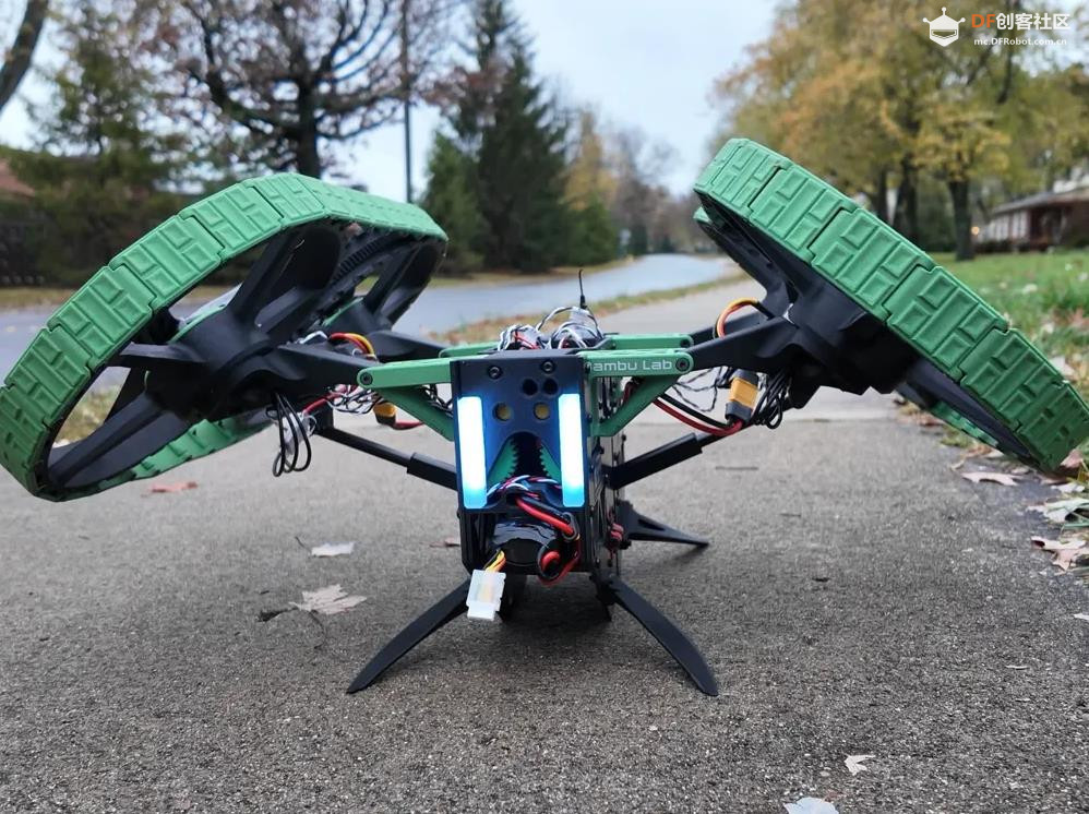
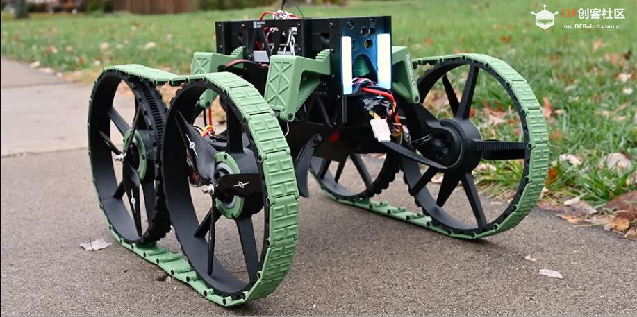
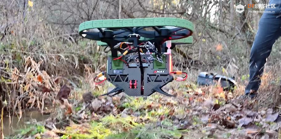
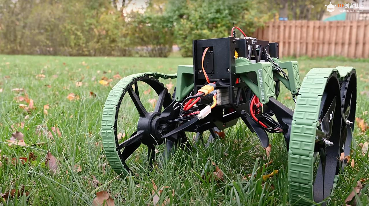


 沪公网安备31011502402448
 置顶卡
置顶卡 变色卡
变色卡 千斤顶
千斤顶

 萌萌哒新人
萌萌哒新人
 活跃会员
活跃会员
 宣传大使
宣传大使
 牛X认证
牛X认证
 创作达人
创作达人
 ARD DAY
 摸鱼团员
摸鱼团员
 志“童”道合
 编辑选择奖
编辑选择奖


