|
13815| 1
|
[入门] 【彩灯调光台】基于Mind+ Ardunio入门教程12 |
|
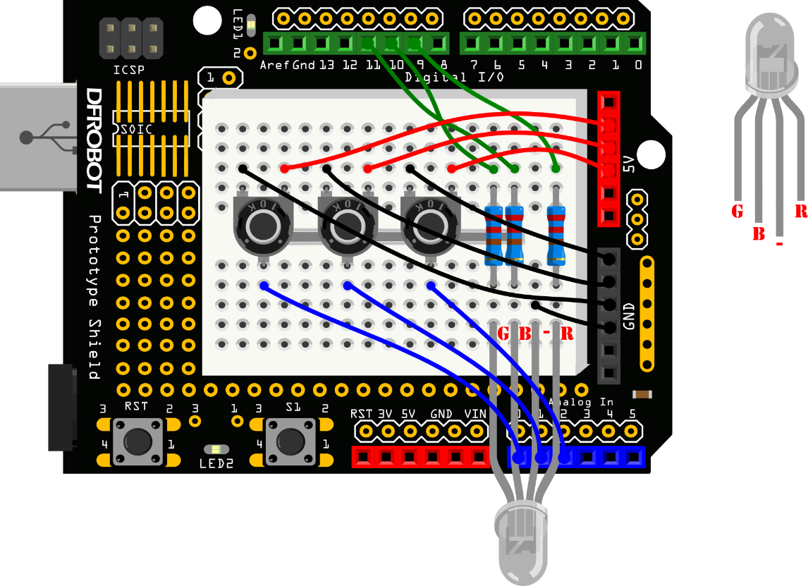
在项目五的时候,我们已经接触过RGB LED了,可以实现变色,这回儿我们需要加入互动元素进去。通过三个电位器来任意变换对应的R、G、B,组合成任何你想要的颜色,在家做个心情灯吧,随心情任意切换。 所需元件 ■ 1× 5mm RGB LED灯  ■ 1× 220欧电阻  ■ 3× 10K电位器  硬件连接  图 12-1彩灯调光台连线图 代码编程 样例程序12-1 [mw_shl_code=c,true]//项目十二 –彩灯调光台 int redPin = 9; // R – digital 9 int greenPin = 10; // G – digital 10 int bluePin = 11; // B – digital 11 int potRedPin = 0; // 电位器1 – analog 0 int potGreenPin = 1; // 电位器2 – analog 1 int potBluePin = 2; // 电位器3 – analog 2 void colorRGB(int, int, int); // 函数声明 void colorRGB(int red, int green, int blue){ //该函数用于显示颜色 analogWrite(redPin,constrain(red,0,255)); analogWrite(greenPin,constrain(green,0,255)); analogWrite(bluePin,constrain(blue,0,255)); } void setup(){ pinMode(redPin,OUTPUT); pinMode(greenPin,OUTPUT); pinMode(bluePin,OUTPUT); Serial.begin(9600); // 初始化串口 } void loop(){ int potRed = analogRead(potRedPin); // potRed存储模拟口0读到的值 int potGreen = analogRead(potGreenPin); // potGreen存储模拟口1读到的值 int potBlue = analogRead(potBluePin); // potBlue存储模拟口2读到的值 int val1 = map(potRed,0,1023,0,255); //通过map函数转换为0~255的值 int val2 = map(potGreen,0,1023,0,255); int val3 = map(potBlue,0,1023,0,255); //串口依次输出Red,Green,Blue对应值 Serial.print("Red:"); Serial.print(val1); Serial.print("Green:"); Serial.print(val2); Serial.print("Blue:"); Serial.println(val3); colorRGB(val1,val2,val3); // 让RGB LED 呈现对应颜色 } [/mw_shl_code] 下载代码,旋转三个电位器,可以变化出不同的颜色。 |
 沪公网安备31011502402448
© 2013-2026 Comsenz Inc. Powered by Discuz! X3.4 Licensed