项目代码
- /*
- ARDUINO DCF77 clock v2025.6
- No library used.
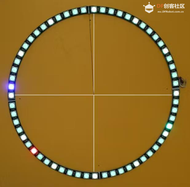
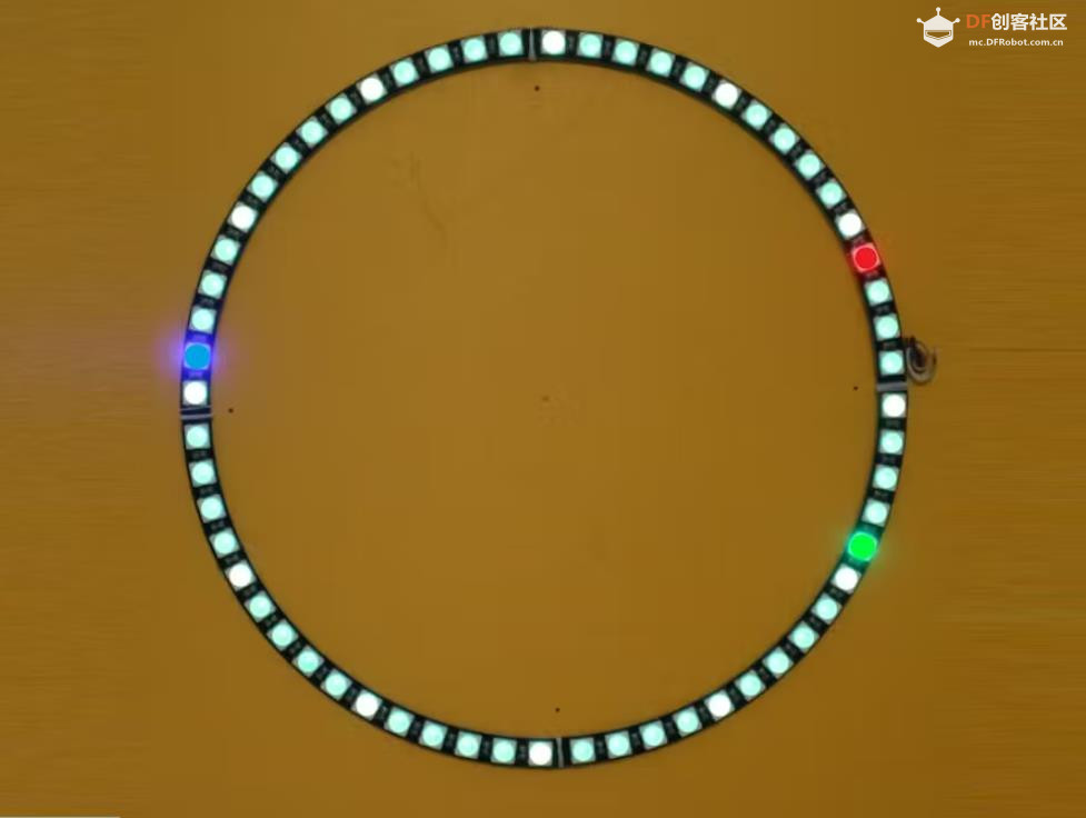
- The clock face will remain blue while no
- valid data are received. It will turn green
- as soon as valid data are decoded.
- If any parity mismatch is detected the
- internal timekeeper continues to work,
- indicated by showing a red clock face.
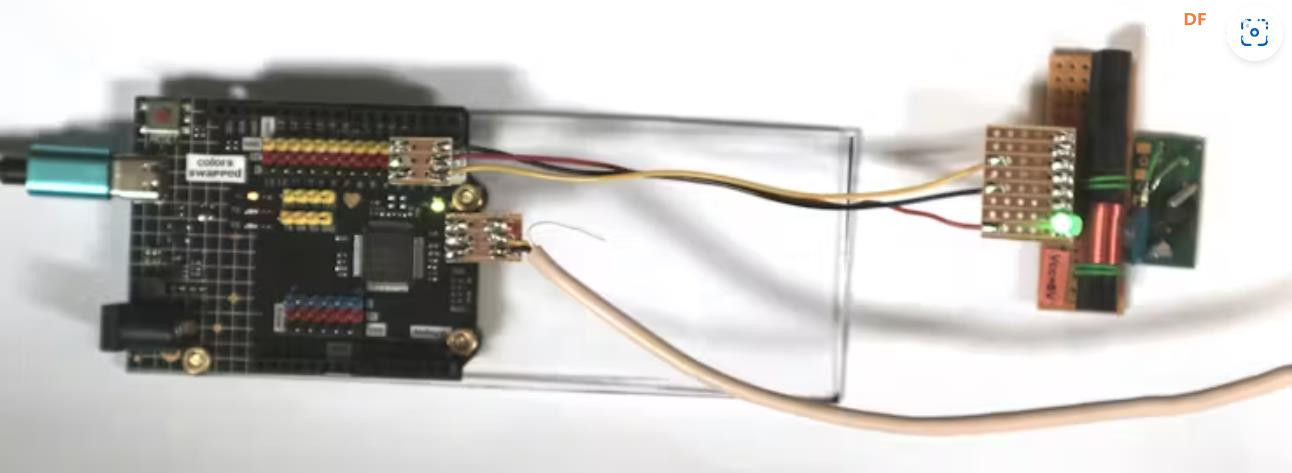
- You can increase the results by turning
- the antenna to the optimum angle.
- If run by using a USB power bank please note
- that it will not work will all power banks.
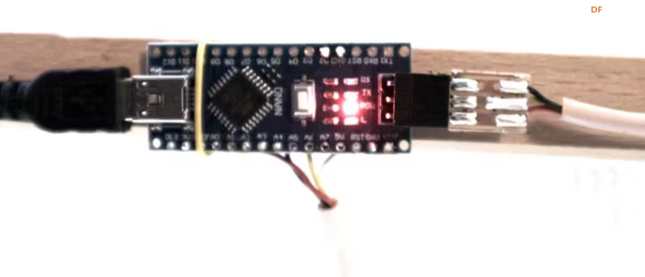
- The LEDs:
- red = second, green = minute, blue 0 hour.
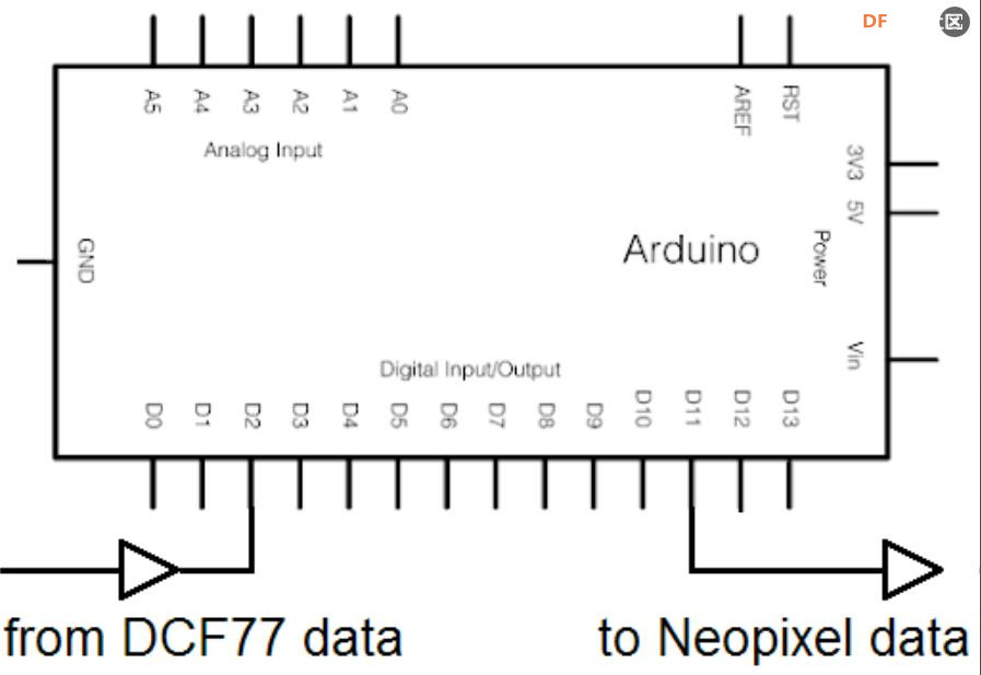
- INTERRUPT_PIN = 2 input for the DCF receiver
- (C) Klaus Koch, klausjkoch@t-online.de
- For modules like HK56 or some others
- you need to define INVERTED
- Check if your module needs INPUT_PULLUP!
- When mounting keep a cetain distance
- between antenna and ARDUINO!
- */
-
- // #define INVERTED
-
- #include <Adafruit_NeoPixel.h>
- /*
- if you use Pin-11 you can use one row
- of the 6-pin ICSP header. Pin-11 is
- just in the middle between GND and Vcc.
- */
- const byte PIN = 11;
- const byte NUMPIXELS = 60;
- Adafruit_NeoPixel strip = Adafruit_NeoPixel(NUMPIXELS, PIN, NEO_GRB + NEO_KHZ800);
- // set ROTATION to correct value
- const byte ROTATION = 45; // 0, 15, 30, 45
- #ifdef INVERTED
- #define START_OF_PULSE FALLING
- #define END_OF_PULSE RISING
- #else
- #define START_OF_PULSE RISING
- #define END_OF_PULSE FALLING
- #endif
-
- const char COMPARE[] = "0??????????????iiiii1mmmmMMMphhhhHHpttttTTwwwMMMMMjjjjJJJJp^";
- const byte INTERRUPT_PIN = 2;
- byte IRQ;
- byte bits[61]; // collect the bit stream
- byte second = 0;
- byte error_second = 0;
- // these constants used only for Serial monitor
- const byte A_1 = 16; // Ankuendigung MEZ/MESZ
- const byte Z1 = 17; // MEZ
- const byte Z2 = 18; // MESZ Sommerzeit
- const byte A_2 = 19; // Ankuendigung Schaltsekunde
- const byte S = 20;
- char outputString[] = "01:34 xyz 01.34.2089 ";
- // positions in string outputString[]:
- const byte H10 = 0;
- const byte H1 = 1;
- const byte m10 = 3;
- const byte m1 = 4;
- const byte W1 = 6;
- const byte W2 = 7;
- const byte D_10 = 10;
- const byte D_1 = 11;
- const byte M10 = 13;
- const byte M1 = 14;
- const byte Y10 = 18;
- const byte Y1 = 19;
- byte HH_temp = 1;
- byte MM_temp = 2;
- byte unsyncH, unsyncM;
- //---------------------------
- const long DARC = 0x010001;
- const long FIVE = 0x020200; // yellow
- const long SECOND = 0x100000; // red
- const long MINUTE = 0x001000; // green
- const byte HOUR = 0x000010; // blue
- //---------------------------
-
- // ---------Hh:Mm Ww, Dd.Mm,20Jj---
- long nextTime;
- volatile boolean bit;
- boolean sync = false;
- // time variables if not sync
- long myMillis;
- boolean HMS_set = false;
-
- // volatile data also used inside ISR
- // start with waiting for RISING:
- // edge getting inverted each time
- volatile long risingTime, fallingTime;
- #ifdef __AVR__
- volatile byte edge = START_OF_PULSE; // UNO R3
- #else
- volatile PinStatus edge = START_OF_PULSE; // UNO R4
- #endif
- volatile boolean event = false;
- volatile boolean endOfMinute = false;
-
- void setup() {
- long t = millis() + 3000;
- boolean b = true;
- pinMode(LED_BUILTIN, OUTPUT);
- Serial.begin(9600);
- #ifndef __AVR__
- // only for ARDUINO UNO R4
- do {
- if (millis() > t) b = false;
- if (Serial) b = false;
- // flash LED 3 times
- digitalWrite(LED_BUILTIN, HIGH);
- delay(500);
- digitalWrite(LED_BUILTIN, LOW);
- delay(500);
- }
- while (b);
- #endif
- // ------------------
- Serial.println("\n" __FILE__);
- Serial.print(__DATE__);
- Serial.print(", ");
- Serial.println(__TIME__);
- Serial.print("interrupt pin = ");
- Serial.println(INTERRUPT_PIN);
- IRQ = digitalPinToInterrupt(INTERRUPT_PIN);
- Serial.print("IRQ number = ");
- Serial.println(IRQ);
- /*
- used for REICHELT B20084A0
- */
- // pinMode(INTERRUPT_PIN, INPUT_PULLUP);
- /*
- any change at INTERRUPT_PIN will
- call the ISR by toggling "edge"
- */
- strip.begin();
- clockFace(HH_temp, MM_temp, second, 0);
- attachInterrupt(IRQ, isr, edge);
- }
-
- void loop() {
- if (event) {
- // called at FALLING edge or endOfMinute
- Serial.print(bit);
- // backgroundcolor:
- long bgc;
- if (HMS_set == false) bgc = 0x000001; // blue
- else if (sync) bgc = 0x000100; // green
- //---------------------------------------
- if (sync || (HMS_set == false) )
- clockFace(HH_temp, MM_temp, second, bgc);
- //---------------------------------------
- if (second < sizeof bits) {
- bits[second] = bit;
- second++;
- } else {
- Serial.println("-error");
- Serial.println(COMPARE);
- sync = false;
- second = 0;
- }
- if (endOfMinute) {
- decodeTime();
- endOfMinute = false;
- second = 0;
- }
- event = false;
- }
- if (!sync && HMS_set && (millis() > myMillis) ) handleUnsync();
- }
-
- void clockFace(byte h, byte m, byte s, long bgc) {
- strip.fill(bgc);
- /*
- the sequence of setPixelColor commands determinds
- who will win when addressing the same LED.
- */
- long color;
- for (int i = 0; i < 60; i = i + 5)
- strip.setPixelColor(i, FIVE);
- strip.setPixelColor(rotate(s), SECOND);
- long mi;
- if (second & 1) mi = MINUTE;
- else mi = MINUTE / 2;
- strip.setPixelColor(rotate(m), mi);
- byte h1 = (h % 12) * 5 + m / 12;
- strip.setPixelColor(rotate(h1), HOUR);
- strip.show();
- }
-
- byte rotate(byte b) {
- return (b + ROTATION) % 60;
- }
-
- // called at the end of a minute:
- void decodeTime() {
- Serial.println("\nend of minute - decoding ...");
- int error = bits[0]; // Bit 0 must be 0 !
- // 1 - 19 reserved
- if (!bits[20]) error += 2; // Bit 20 must be 1
- boolean p1 = parity(21, 28);
- boolean p2 = parity(29, 35);
- boolean p3 = parity(36, 58);
- if (p1) error += 4;
- if (p2) error += 8;
- if (p3) error += 16;
- // convert to printable date:
- // minutes:
- outputString[m1] = bin_to_int(21, 24); // 1 2 4 8
- outputString[m10] = bin_to_int(25, 27); // 10 20 40
- MM_temp = 10 * outputString[m10] + outputString[m1];
- // 28 = P1
- // hours:
- outputString[H1] = bin_to_int(29, 32); // 1 2 4 8
- outputString[H10] = bin_to_int(33, 34); // 10 20
- HH_temp = 10 * outputString[H10] + outputString[H1];
- // 35 = P2
- // day of month:
- outputString[D_1] = bin_to_int(36, 39); // 1 2 4 8
- outputString[D_10] = bin_to_int(40, 41); // 10 20
- // month:
- outputString[M1] = bin_to_int(45, 48);
- outputString[M10] = bits[49];
- // year:
- outputString[Y1] = bin_to_int(50, 53);
- outputString[Y10] = bin_to_int(54, 57);
- // plausibility tests:
- // 01:34 67, 01.34.2089
- // Hh:Mm Ww, Dd.Mm,20Jj---
- if (invalid(H10, 23)) error += 0x020; // HH
- if (invalid(m10, 59)) error += 0x040; // mm
- if (invalid(D_10, 31)) error += 0x080; // DD
- if (invalid(M10, 12)) error += 0x100; // MM
- if (invalid(Y10, 99)) error += 0x200; // YY
- // convert numbers to ASCII:
- for (byte i = 0; i < sizeof outputString - 1; i++) {
- char *x = &outputString[i]; // was byte for R3
- if (*x == constrain(*x, 0, 9)) *x = *x + '0';
- if (*x == constrain(*x, 10, 31)) error += 0x400;
- }
- // 58 = P3
- // 59 has to be missing
- sync = error == 0;
- if (sync) {
- Serial.print(" A1 = ");
- Serial.print(bits[A_1]);
- Serial.print(", Z1 = ");
- Serial.print(bits[Z1]);
- Serial.print(", Z2 = ");
- Serial.print(bits[Z2]);
- Serial.print(", A2 = ");
- Serial.print(bits[A_2]);
- Serial.print(", S = ");
- Serial.println(bits[S]);
- Serial.println(outputString);
- // prepare for not sync:
- HMS_set = true;
- myMillis = millis();
- //-----------------------------------------------------
- clockFace(HH_temp, MM_temp, second, 0x000100); // green
- //-----------------------------------------------------
- // copy time for use if not sync:
- unsyncH = HH_temp;
- unsyncM = MM_temp;
- } else {
- // not sync:
- Serial.print(" Error: ");
- Serial.println(error, BIN);
- }
- Serial.println(COMPARE);
- }
-
- boolean invalid(byte i, byte max) {
- return outputString[i] * 10 + outputString[i + 1] > max;
- }
-
- // converts BCD into byte
- byte bin_to_int(byte a, byte b) {
- byte value = 0;
- for (byte i = a, j = 0; i <= b; i++, j++)
- if (bits[i]) bitSet(value, j);
- return value;
- }
-
- // https://rn-wissen.de/wiki/index.php?title=DCF77-Decoder_als_Bascom-Library
- byte parity(byte a, byte b) {
- byte p = 0;
- for (byte i = a; i <= b; i++) p = p + bits[i];
- return p & 1;
- }
-
- void handleUnsync() {
- error_second++;
- if (error_second >= 60) {
- error_second = 0;
- unsyncM++;
- if (unsyncM >= 60) {
- unsyncM = 0;
- unsyncH++;
- if (unsyncH >= 12) unsyncH = 0;
- }
- }
- //---------------------------------------------------------
- clockFace(unsyncH, unsyncM, error_second, 0x010000); // red
- //---------------------------------------------------------
- myMillis = myMillis + 1000;
- }
-
- // ***************************************************
- const int MIN_SHORT = 70;
- const int MAX_SHORT = 140;
- const int MINUTE_GAP = 1500;
- const int MIN_PAUSE = 750;
-
- void isr() {
- // isr - called when signal on Pin 2 changes
- // detect cause of interrupt
- static long risingTime, fallingTime;
- long now = millis();
- if (edge == START_OF_PULSE) {
- risingTime = now;
- digitalWrite(LED_BUILTIN, HIGH);
- long downTime = now - fallingTime;
- // modify IRQ:
- edge = END_OF_PULSE; // invert
- attachInterrupt(IRQ, isr, edge);
- if (downTime < MIN_PAUSE) return;
- endOfMinute = downTime > MINUTE_GAP;
- if (endOfMinute) event = true;
- }
- else {
- // falling:
- fallingTime = now;
- digitalWrite(LED_BUILTIN, LOW);
- long upTime = now - risingTime;
- // modify IRQ:
- edge = START_OF_PULSE; // invert
- attachInterrupt(IRQ, isr, edge);
- if (upTime < MIN_SHORT) return;
- bit = upTime > MAX_SHORT;
- event = true;
- }
- }
|


 沪公网安备31011502402448
 置顶卡
置顶卡 变色卡
变色卡 千斤顶
千斤顶
 萌萌哒新人
萌萌哒新人
 活跃会员
活跃会员
 宣传大使
宣传大使
 牛X认证
牛X认证
 创作达人
创作达人
 ARD DAY
 摸鱼团员
摸鱼团员
 志“童”道合
 编辑选择奖
编辑选择奖


