本帖最后由 无垠的广袤 于 2025-5-13 02:34 编辑
Beetle 树莓派RP2350 - 便携INA219功率计
本文介绍了 DFRobot Beetle RP2350 开发板结合 INA219 模块实现功率计,并通过 LabVIEW 上位机串口采集 INA219 电流、电压数据的项目设计。
项目介绍
本项目包括 INA219(关键部件)芯片介绍、工作原理、参数特点等信息,在此基础上实现工程代码编写、硬件测试等流程,最终实现功率计制作。结合LabVIEW上位机,实现功率数据采集和曲线分析等。
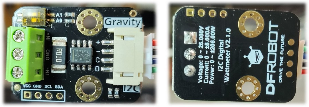
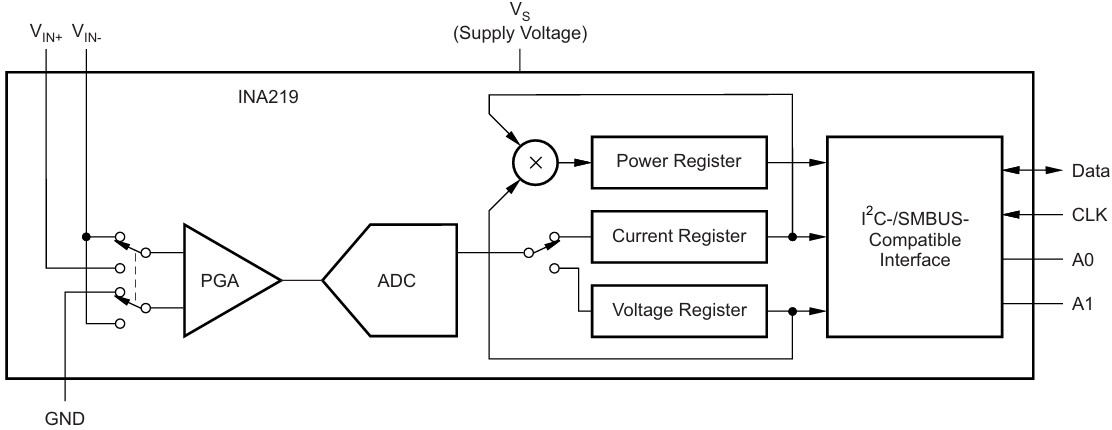
INA219 模块
DFRobot Gravity:I2C数字功率计 是一款可测量 26V, 8A 以内各类电子模块、用电设备的电压、电流和功率,最大相对误差不超过±0.2%的高分辨、高精度、大量程测量模块(首次使用需进行手动校准)。 可用于太阳能系统、电池库仑计、电机、主控板或电子模块的功耗测量、电池续航评估与实时电源参数在线监控。
模块采用 TI INA219 零温漂电流/功率监控芯片和 2W 大功率低温漂 10mΩ 合金采样电阻, 电压和电流分辨率分别可达 4mV 与 1mA, 在满量程测量条件下,电压与电流的最大测量相对误差不超过±0.2%, 并提供4个可通过拨码开关配置的I2C地址。 模块可对双向高侧电流(流经电源或电池正极的电流)进行准确测量,这在太阳能或库仑计应用,电池既需要充电,也需要放电的场合尤为有用, 用户可通过电流的正负读数了解电池的充放电状态,也可以了解电池的冲放电的实时电压、电流与功率。 在电机应用场景,可通过实时监控电机电流是否由于堵转或负载过大导致电流过大,从而及时采取保护措施。 此外,也可以使用该模块测量各类电子模块或整个项目的实时功耗,从而评估电池的续航时间。
特性高精度、高分辨率、大量程、低温漂 双向电流高侧测量 兼容3.3V/5V控制器 精致小巧,方便项目嵌入
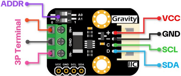
接口说明
[td]
| 名称 | 功能描述 | VCC | 电源正极(3.3~5.5V) | GND | 电源负极 | SCL | I2C时钟线 | SDA | I2C数据线 | ADDR | I2C地址选择拨码开关 | 3P TERMINAL | 电压与电流测量接线柱3P |
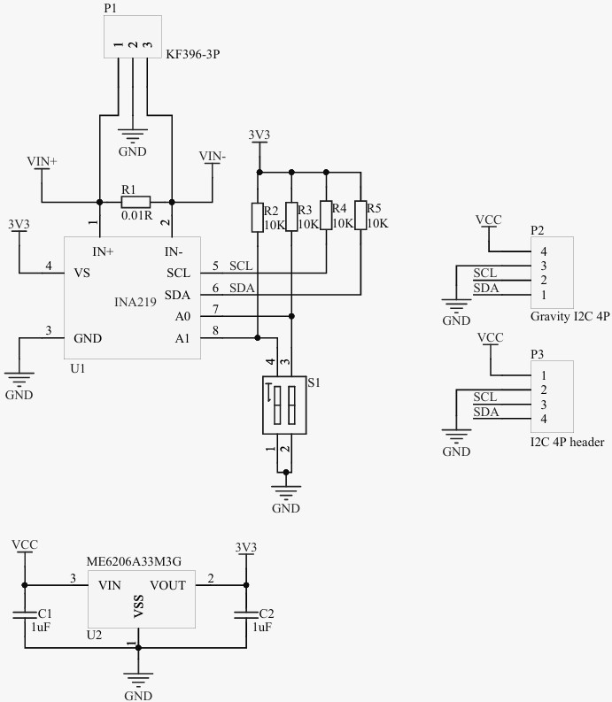
模块原理图
INA 原理图
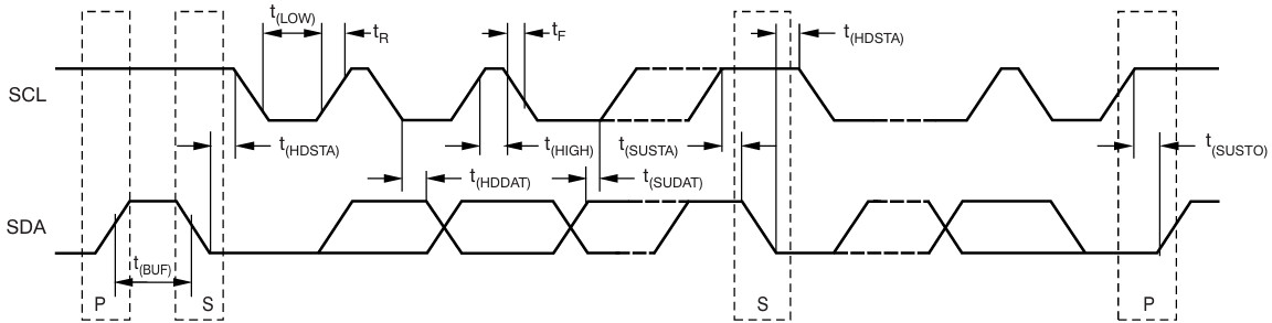
总线时序图
IIC 通信起始地址为 0x40
工程代码
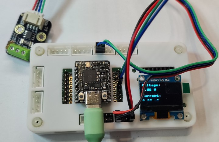
通过复用 IIC 引脚 GPIO4 和 GPIO5 ,实现 INA219 模块的数据采集、终端打印以及 OLED 显示。 上传 ina219.py 至芯片根目录
- # The MIT License (MIT)
- #
- # Copyright (c) 2017 Dean Miller for Adafruit Industries
- #
- # Permission is hereby granted, free of charge, to any person obtaining a copy
- # of this software and associated documentation files (the "Software"), to deal
- # in the Software without restriction, including without limitation the rights
- # to use, copy, modify, merge, publish, distribute, sublicense, and/or sell
- # copies of the Software, and to permit persons to whom the Software is
- # furnished to do so, subject to the following conditions:
- #
- # The above copyright notice and this permission notice shall be included in
- # all copies or substantial portions of the Software.
- #
- # THE SOFTWARE IS PROVIDED "AS IS", WITHOUT WARRANTY OF ANY KIND, EXPRESS OR
- # IMPLIED, INCLUDING BUT NOT LIMITED TO THE WARRANTIES OF MERCHANTABILITY,
- # FITNESS FOR A PARTICULAR PURPOSE AND NONINFRINGEMENT. IN NO EVENT SHALL THE
- # AUTHORS OR COPYRIGHT HOLDERS BE LIABLE FOR ANY CLAIM, DAMAGES OR OTHER
- # LIABILITY, WHETHER IN AN ACTION OF CONTRACT, TORT OR OTHERWISE, ARISING FROM,
- # OUT OF OR IN CONNECTION WITH THE SOFTWARE OR THE USE OR OTHER DEALINGS IN
- # THE SOFTWARE.
- """
- `adafruit_ina219`
- ====================================================
-
- CircuitPython/MicroPython driver for the INA219 current sensor.
-
- * Author(s): Dean Miller
- """
-
- from micropython import const
- # from adafruit_bus_device.i2c_device import I2CDevice
-
- __version__ = "0.0.0-auto.0"
- __repo__ = "https://github.com/robert-hh/INA219.git"
-
- # Bits
- # pylint: disable=bad-whitespace
- _READ = const(0x01)
-
- # Config Register (R/W)
- _REG_CONFIG = const(0x00)
- _CONFIG_RESET = const(0x8000) # Reset Bit
-
- _CONFIG_BVOLTAGERANGE_MASK = const(0x2000) # Bus Voltage Range Mask
- _CONFIG_BVOLTAGERANGE_16V = const(0x0000) # 0-16V Range
- _CONFIG_BVOLTAGERANGE_32V = const(0x2000) # 0-32V Range
-
- _CONFIG_GAIN_MASK = const(0x1800) # Gain Mask
- _CONFIG_GAIN_1_40MV = const(0x0000) # Gain 1, 40mV Range
- _CONFIG_GAIN_2_80MV = const(0x0800) # Gain 2, 80mV Range
- _CONFIG_GAIN_4_160MV = const(0x1000) # Gain 4, 160mV Range
- _CONFIG_GAIN_8_320MV = const(0x1800) # Gain 8, 320mV Range
-
- _CONFIG_BADCRES_MASK = const(0x0780) # Bus ADC Resolution Mask
- _CONFIG_BADCRES_9BIT = const(0x0080) # 9-bit bus res = 0..511
- _CONFIG_BADCRES_10BIT = const(0x0100) # 10-bit bus res = 0..1023
- _CONFIG_BADCRES_11BIT = const(0x0200) # 11-bit bus res = 0..2047
- _CONFIG_BADCRES_12BIT = const(0x0400) # 12-bit bus res = 0..4097
-
- _CONFIG_SADCRES_MASK = const(0x0078) # Shunt ADC Res. & Avg. Mask
- _CONFIG_SADCRES_9BIT_1S_84US = const(0x0000) # 1 x 9-bit shunt sample
- _CONFIG_SADCRES_10BIT_1S_148US = const(0x0008) # 1 x 10-bit shunt sample
- _CONFIG_SADCRES_11BIT_1S_276US = const(0x0010) # 1 x 11-bit shunt sample
- _CONFIG_SADCRES_12BIT_1S_532US = const(0x0018) # 1 x 12-bit shunt sample
- _CONFIG_SADCRES_12BIT_2S_1060US = const(0x0048) # 2 x 12-bit sample average
- _CONFIG_SADCRES_12BIT_4S_2130US = const(0x0050) # 4 x 12-bit sample average
- _CONFIG_SADCRES_12BIT_8S_4260US = const(0x0058) # 8 x 12-bit sample average
- _CONFIG_SADCRES_12BIT_16S_8510US = const(0x0060) # 16 x 12-bit sample average
- _CONFIG_SADCRES_12BIT_32S_17MS = const(0x0068) # 32 x 12-bit sample average
- _CONFIG_SADCRES_12BIT_64S_34MS = const(0x0070) # 64 x 12-bit sample average
- _CONFIG_SADCRES_12BIT_128S_69MS = const(0x0078) # 128 x 12-bit sample average
-
- _CONFIG_MODE_MASK = const(0x0007) # Operating Mode Mask
- _CONFIG_MODE_POWERDOWN = const(0x0000)
- _CONFIG_MODE_SVOLT_TRIGGERED = const(0x0001)
- _CONFIG_MODE_BVOLT_TRIGGERED = const(0x0002)
- _CONFIG_MODE_SANDBVOLT_TRIGGERED = const(0x0003)
- _CONFIG_MODE_ADCOFF = const(0x0004)
- _CONFIG_MODE_SVOLT_CONTINUOUS = const(0x0005)
- _CONFIG_MODE_BVOLT_CONTINUOUS = const(0x0006)
- _CONFIG_MODE_SANDBVOLT_CONTINUOUS = const(0x0007)
-
- # SHUNT VOLTAGE REGISTER (R)
- _REG_SHUNTVOLTAGE = const(0x01)
-
- # BUS VOLTAGE REGISTER (R)
- _REG_BUSVOLTAGE = const(0x02)
-
- # POWER REGISTER (R)
- _REG_POWER = const(0x03)
-
- # CURRENT REGISTER (R)
- _REG_CURRENT = const(0x04)
-
- # CALIBRATION REGISTER (R/W)
- _REG_CALIBRATION = const(0x05)
- # pylint: enable=bad-whitespace
-
-
- def _to_signed(num):
- if num > 0x7FFF:
- num -= 0x10000
- return num
-
-
- class INA219:
- """Driver for the INA219 current sensor"""
- def __init__(self, i2c_device, addr=0x40):
- self.i2c_device = i2c_device
-
- self.i2c_addr = addr
- self.buf = bytearray(2)
- # Multiplier in mA used to determine current from raw reading
- self._current_lsb = 0
- # Multiplier in W used to determine power from raw reading
- self._power_lsb = 0
-
- # Set chip to known config values to start
- self._cal_value = 4096
- self.set_calibration_32V_2A()
-
- def _write_register(self, reg, value):
- self.buf[0] = (value >> 8) & 0xFF
- self.buf[1] = value & 0xFF
- self.i2c_device.writeto_mem(self.i2c_addr, reg, self.buf)
-
- def _read_register(self, reg):
- self.i2c_device.readfrom_mem_into(self.i2c_addr, reg & 0xff, self.buf)
- value = (self.buf[0] << 8) | (self.buf[1])
- return value
-
- @property
- def shunt_voltage(self):
- """The shunt voltage (between V+ and V-) in Volts (so +-.327V)"""
- value = _to_signed(self._read_register(_REG_SHUNTVOLTAGE))
- # The least signficant bit is 10uV which is 0.00001 volts
- return value * 0.00001
-
- @property
- def bus_voltage(self):
- """The bus voltage (between V- and GND) in Volts"""
- raw_voltage = self._read_register(_REG_BUSVOLTAGE)
-
- # Shift to the right 3 to drop CNVR and OVF and multiply by LSB
- # Each least signficant bit is 4mV
- voltage_mv = _to_signed(raw_voltage >> 3) * 4
- return voltage_mv * 0.001
-
- @property
- def current(self):
- """The current through the shunt resistor in milliamps."""
- # Sometimes a sharp load will reset the INA219, which will
- # reset the cal register, meaning CURRENT and POWER will
- # not be available ... athis by always setting a cal
- # value even if it's an unfortunate extra step
- self._write_register(_REG_CALIBRATION, self._cal_value)
-
- # Now we can safely read the CURRENT register!
- raw_current = _to_signed(self._read_register(_REG_CURRENT))
- return raw_current * self._current_lsb
-
- def set_calibration_32V_2A(self): # pylint: disable=invalid-name
- """Configures to INA219 to be able to measure up to 32V and 2A
- of current. Counter overflow occurs at 3.2A.
-
- ..note :: These calculations assume a 0.1 shunt ohm resistor"""
- # By default we use a pretty huge range for the input voltage,
- # which probably isn't the most appropriate choice for system
- # that don't use a lot of power. But all of the calculations
- # are shown below if you want to change the settings. You will
- # also need to change any relevant register settings, such as
- # setting the VBUS_MAX to 16V instead of 32V, etc.
-
- # VBUS_MAX = 32V (Assumes 32V, can also be set to 16V)
- # VSHUNT_MAX = 0.32 (Assumes Gain 8, 320mV, can also be
- # 0.16, 0.08, 0.04)
- # RSHUNT = 0.1 (Resistor value in ohms)
-
- # 1. Determine max possible current
- # MaxPossible_I = VSHUNT_MAX / RSHUNT
- # MaxPossible_I = 3.2A
-
- # 2. Determine max expected current
- # MaxExpected_I = 2.0A
-
- # 3. Calculate possible range of LSBs (Min = 15-bit, Max = 12-bit)
- # MinimumLSB = MaxExpected_I/32767
- # MinimumLSB = 0.000061 (61uA per bit)
- # MaximumLSB = MaxExpected_I/4096
- # MaximumLSB = 0,000488 (488uA per bit)
-
- # 4. Choose an LSB between the min and max values
- # (Preferrably a roundish number close to MinLSB)
- # CurrentLSB = 0.0001 (100uA per bit)
- self._current_lsb = .1 # Current LSB = 100uA per bit
-
- # 5. Compute the calibration register
- # Cal = trunc (0.04096 / (Current_LSB * RSHUNT))
- # Cal = 4096 (0x1000)
-
- self._cal_value = 4096
-
- # 6. Calculate the power LSB
- # PowerLSB = 20 * CurrentLSB
- # PowerLSB = 0.002 (2mW per bit)
- self._power_lsb = .002 # Power LSB = 2mW per bit
-
- # 7. Compute the maximum current and shunt voltage values before
- # overflow
- #
- # Max_Current = Current_LSB * 32767
- # Max_Current = 3.2767A before overflow
- #
- # If Max_Current > Max_Possible_I then
- # Max_Current_Before_Overflow = MaxPossible_I
- # Else
- # Max_Current_Before_Overflow = Max_Current
- # End If
- #
- # Max_ShuntVoltage = Max_Current_Before_Overflow * RSHUNT
- # Max_ShuntVoltage = 0.32V
- #
- # If Max_ShuntVoltage >= VSHUNT_MAX
- # Max_ShuntVoltage_Before_Overflow = VSHUNT_MAX
- # Else
- # Max_ShuntVoltage_Before_Overflow = Max_ShuntVoltage
- # End If
-
- # 8. Compute the Maximum Power
- # MaximumPower = Max_Current_Before_Overflow * VBUS_MAX
- # MaximumPower = 3.2 * 32V
- # MaximumPower = 102.4W
-
- # Set Calibration register to 'Cal' calculated above
- self._write_register(_REG_CALIBRATION, self._cal_value)
-
- # Set Config register to take into account the settings above
- config = (_CONFIG_BVOLTAGERANGE_32V |
- _CONFIG_GAIN_8_320MV |
- _CONFIG_BADCRES_12BIT |
- _CONFIG_SADCRES_12BIT_1S_532US |
- _CONFIG_MODE_SANDBVOLT_CONTINUOUS)
- self._write_register(_REG_CONFIG, config)
-
- def set_calibration_32V_1A(self): # pylint: disable=invalid-name
- """Configures to INA219 to be able to measure up to 32V and 1A of
- current. Counter overflow occurs at 1.3A.
-
- .. note:: These calculations assume a 0.1 ohm shunt resistor."""
- # By default we use a pretty huge range for the input voltage,
- # which probably isn't the most appropriate choice for system
- # that don't use a lot of power. But all of the calculations
- # are shown below if you want to change the settings. You will
- # also need to change any relevant register settings, such as
- # setting the VBUS_MAX to 16V instead of 32V, etc.
-
- # VBUS_MAX = 32V (Assumes 32V, can also be set to 16V)
- # VSHUNT_MAX = 0.32 (Assumes Gain 8, 320mV, can also be
- # 0.16, 0.08, 0.04)
- # RSHUNT = 0.1 (Resistor value in ohms)
-
- # 1. Determine max possible current
- # MaxPossible_I = VSHUNT_MAX / RSHUNT
- # MaxPossible_I = 3.2A
-
- # 2. Determine max expected current
- # MaxExpected_I = 1.0A
-
- # 3. Calculate possible range of LSBs (Min = 15-bit, Max = 12-bit)
- # MinimumLSB = MaxExpected_I/32767
- # MinimumLSB = 0.0000305 (30.5uA per bit)
- # MaximumLSB = MaxExpected_I/4096
- # MaximumLSB = 0.000244 (244uA per bit)
-
- # 4. Choose an LSB between the min and max values
- # (Preferrably a roundish number close to MinLSB)
- # CurrentLSB = 0.0000400 (40uA per bit)
- self._current_lsb = 0.04 # In milliamps
-
- # 5. Compute the calibration register
- # Cal = trunc (0.04096 / (Current_LSB * RSHUNT))
- # Cal = 10240 (0x2800)
-
- self._cal_value = 10240
-
- # 6. Calculate the power LSB
- # PowerLSB = 20 * CurrentLSB
- # PowerLSB = 0.0008 (800uW per bit)
- self._power_lsb = 0.0008
-
- # 7. Compute the maximum current and shunt voltage values before
- # overflow
- #
- # Max_Current = Current_LSB * 32767
- # Max_Current = 1.31068A before overflow
- #
- # If Max_Current > Max_Possible_I then
- # Max_Current_Before_Overflow = MaxPossible_I
- # Else
- # Max_Current_Before_Overflow = Max_Current
- # End If
- #
- # ... In this case, we're good though since Max_Current is less than
- # MaxPossible_I
- #
- # Max_ShuntVoltage = Max_Current_Before_Overflow * RSHUNT
- # Max_ShuntVoltage = 0.131068V
- #
- # If Max_ShuntVoltage >= VSHUNT_MAX
- # Max_ShuntVoltage_Before_Overflow = VSHUNT_MAX
- # Else
- # Max_ShuntVoltage_Before_Overflow = Max_ShuntVoltage
- # End If
-
- # 8. Compute the Maximum Power
- # MaximumPower = Max_Current_Before_Overflow * VBUS_MAX
- # MaximumPower = 1.31068 * 32V
- # MaximumPower = 41.94176W
-
- # Set Calibration register to 'Cal' calculated above
- self._write_register(_REG_CALIBRATION, self._cal_value)
-
- # Set Config register to take into account the settings above
- config = (_CONFIG_BVOLTAGERANGE_32V |
- _CONFIG_GAIN_8_320MV |
- _CONFIG_BADCRES_12BIT |
- _CONFIG_SADCRES_12BIT_1S_532US |
- _CONFIG_MODE_SANDBVOLT_CONTINUOUS)
- self._write_register(_REG_CONFIG, config)
-
- def set_calibration_16V_400mA(self): # pylint: disable=invalid-name
- """Configures to INA219 to be able to measure up to 16V and 400mA of
- current. Counter overflow occurs at 1.6A.
-
- .. note:: These calculations assume a 0.1 ohm shunt resistor."""
- # Calibration which uses the highest precision for
- # current measurement (0.1mA), at the expense of
- # only supporting 16V at 400mA max.
-
- # VBUS_MAX = 16V
- # VSHUNT_MAX = 0.04 (Assumes Gain 1, 40mV)
- # RSHUNT = 0.1 (Resistor value in ohms)
-
- # 1. Determine max possible current
- # MaxPossible_I = VSHUNT_MAX / RSHUNT
- # MaxPossible_I = 0.4A
-
- # 2. Determine max expected current
- # MaxExpected_I = 0.4A
-
- # 3. Calculate possible range of LSBs (Min = 15-bit, Max = 12-bit)
- # MinimumLSB = MaxExpected_I/32767
- # MinimumLSB = 0.0000122 (12uA per bit)
- # MaximumLSB = MaxExpected_I/4096
- # MaximumLSB = 0.0000977 (98uA per bit)
-
- # 4. Choose an LSB between the min and max values
- # (Preferrably a roundish number close to MinLSB)
- # CurrentLSB = 0.00005 (50uA per bit)
- self._current_lsb = 0.05 # in milliamps
-
- # 5. Compute the calibration register
- # Cal = trunc (0.04096 / (Current_LSB * RSHUNT))
- # Cal = 8192 (0x2000)
-
- self._cal_value = 8192
-
- # 6. Calculate the power LSB
- # PowerLSB = 20 * CurrentLSB
- # PowerLSB = 0.001 (1mW per bit)
- self._power_lsb = 0.001
-
- # 7. Compute the maximum current and shunt voltage values before
- # overflow
- #
- # Max_Current = Current_LSB * 32767
- # Max_Current = 1.63835A before overflow
- #
- # If Max_Current > Max_Possible_I then
- # Max_Current_Before_Overflow = MaxPossible_I
- # Else
- # Max_Current_Before_Overflow = Max_Current
- # End If
- #
- # Max_Current_Before_Overflow = MaxPossible_I
- # Max_Current_Before_Overflow = 0.4
- #
- # Max_ShuntVoltage = Max_Current_Before_Overflow * RSHUNT
- # Max_ShuntVoltage = 0.04V
- #
- # If Max_ShuntVoltage >= VSHUNT_MAX
- # Max_ShuntVoltage_Before_Overflow = VSHUNT_MAX
- # Else
- # Max_ShuntVoltage_Before_Overflow = Max_ShuntVoltage
- # End If
- #
- # Max_ShuntVoltage_Before_Overflow = VSHUNT_MAX
- # Max_ShuntVoltage_Before_Overflow = 0.04V
-
- # 8. Compute the Maximum Power
- # MaximumPower = Max_Current_Before_Overflow * VBUS_MAX
- # MaximumPower = 0.4 * 16V
- # MaximumPower = 6.4W
-
- # Set Calibration register to 'Cal' calculated above
- self._write_register(_REG_CALIBRATION, self._cal_value)
-
- # Set Config register to take into account the settings above
- config = (_CONFIG_BVOLTAGERANGE_16V |
- _CONFIG_GAIN_1_40MV |
- _CONFIG_BADCRES_12BIT |
- _CONFIG_SADCRES_12BIT_1S_532US |
- _CONFIG_MODE_SANDBVOLT_CONTINUOUS)
- self._write_register(_REG_CONFIG, config)
终端打印
- '''
- Name: INA219 demo, print voltage and current
- Version: v1.0
- Date: 2025.05
- Author: ljl
- Other: Shell print voltage and current tested by INA219 sensor.
- '''
-
- from machine import I2C, Pin
- from ina219 import INA219
- from time import sleep
- import utime
-
- # I2C Initialization (SDA: GP0, SCL: GP1)
- i2c = I2C(0, scl=Pin(1), sda=Pin(0), freq=400000)
-
- # I2C-Scan - searching for connected Devices on the I2C Bus
- devices = i2c.scan()
- if devices:
- print("I2C devices found:", [hex(device) for device in devices])
- else:
- print("No I2C devices found. Check connections!")
- while True:
- pass
-
-
- # INA219-Sensor Initialization
- ina = INA219(i2c)
- ina.set_calibration_32V_1A()
-
- # main loop
- while True:
- try:
- current = ina.current
- voltage = ina.bus_voltage
-
- if current <= 0.05:
- current = 0
-
- if voltage <= 0.05:
- voltage = 0
-
- print("{:.2f} mA {:.2f} V".format(current, voltage))
- utime.sleep_ms(250)
-
- except Exception as e:
- print("Error reading INA219:", e)
-
- sleep(1)OLED 显示'''
- Name: INA219 demo, print and display voltage and current
- Version: v1.0
- Date: 2025.05
- Author: ljl
- Other: Shell print and OLED display voltage and current tested by INA219 sensor.
- '''
-
- from machine import I2C, Pin
- from ina219 import INA219
- from time import sleep
- import utime
- import ssd1306
-
- # ==== Initialized IIC OLED ====
- i2c = I2C(0, scl=Pin(5), sda=Pin(4),freq=400000)
- oled_width = 128
- oled_height = 64
- oled = ssd1306.SSD1306_I2C(oled_width, oled_height, i2c)
-
- #i2c = I2C(0, scl=Pin(1), sda=Pin(0),freq=400000)
- # I2C-Scan - searching for connected Devices on the I2C Bus
- devices = i2c.scan()
- if devices:
- print("I2C devices found:", [hex(device) for device in devices])
- else:
- print("No I2C devices found. Check connections!")
- while True:
- pass
-
-
- # INA219-Sensor Initialization
- ina = INA219(i2c)
- ina.set_calibration_32V_1A()
-
- def display_VC(voltage,current): # voltage and current
- oled.fill(0) # 清屏
- oled.text("Voltage: ", 0, 0)
- oled.text("{:.2f} V".format(voltage), 0, 15)
- oled.text("Current: ", 0, 35)
- oled.text("{:.2f} mA".format(current), 0, 50)
- oled.show()
- # main loop
- while True:
- try:
- current = ina.current
- voltage = ina.bus_voltage
-
- if current <= 0.05:
- current = 0
-
- if voltage <= 0.05:
- voltage = 0
-
- print("{:.2f} mA {:.2f} V".format(current, voltage))
- display_VC(voltage,current);
- utime.sleep_ms(250)
-
- except Exception as e:
- print("Error reading INA219:", e)
-
- sleep(1)
LabVIEW上位机
介绍了 LabVIEW 上位机向单片机发送串口指令,获取 INA219 传感器电压和电流数据,并绘制功率数值演化曲线。
代码
串口以十六进制发送 55 AA 10 或 55 AA 11 分别获得电压和电流数值。
- '''
- Name: INA219 demo, print and UART voltage and current
- Version: v1.0
- Date: 2025.05
- Author: ljl
- Other: UART send voltage and current which data tested by INA219 sensor.
- '''
-
- from machine import Pin, I2C, UART
- from ina219 import INA219
- import utime
- import ssd1306
-
- # ==== Initialized IIC OLED ====
- i2c = I2C(0, scl=Pin(5), sda=Pin(4),freq=400000)
- oled_width = 128
- oled_height = 64
- oled = ssd1306.SSD1306_I2C(oled_width, oled_height, i2c)
-
- #i2c = I2C(0, scl=Pin(1), sda=Pin(0),freq=400000)
- # I2C-Scan - searching for connected Devices on the I2C Bus
- devices = i2c.scan()
- if devices:
- print("I2C devices found:", [hex(device) for device in devices])
- else:
- print("No I2C devices found. Check connections!")
- while True:
- pass
-
- # INA219-Sensor Initialization
- ina = INA219(i2c)
- ina.set_calibration_32V_1A()
-
- # Initialize UART (change pins as needed for your board)
- uart = machine.UART(1, baudrate=9600, tx=Pin(8), rx=Pin(9))
- comdata = bytearray(3)
-
- def display_VC(voltage,current): # voltage and current
- oled.fill(0) # 清屏
- oled.text("Voltage: ", 0, 0)
- oled.text("{:.2f} V".format(voltage), 0, 15)
- oled.text("Current: ", 0, 35)
- oled.text("{:.2f} mA".format(current), 0, 50)
- oled.show()
-
- def receive_data():
- for i in range(3):
- while not uart.any(): # Wait for data to be available
- pass
- comdata = uart.read(1)[0] # Read one byte
- utime.sleep_ms(2) # Small delay between bytes
-
- def test_do_data():
- if comdata[0] == 0x55 and comdata[1] == 0xAA:
- try:
- if comdata[2] == 0x10:
- voltage = ina.bus_voltage
- if voltage <= 0.05:
- voltage = 0
- uart.write("{:.2f}\r\n".format(voltage))
- elif comdata[2] == 0x11:
- current = ina.current
- if current <= 0.05:
- current = 0
- uart.write("{:.2f}\r\n".format(current))
- except Exception as e:
- uart.write("Error reading sensor.\r\n")
-
- # Serial acquire data
- def uart_acquire():
- if uart.any() >= 3:
- receive_data()
- test_do_data()
- utime.sleep_ms(0) # Small delay to prevent busy-wait
-
- # main loop
- while True:
- uart_acquire()
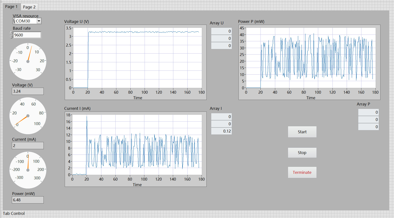
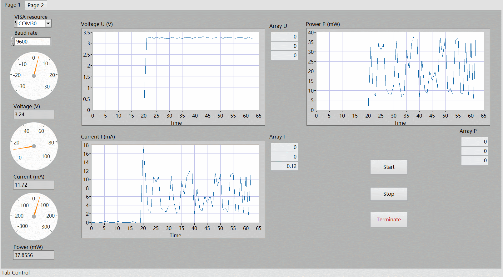
前面板
功能实现:
配置串口 运行程序 点击 Start 开始采集数据 点击 Stop 停止采集 点击 Terminate 终止程序。
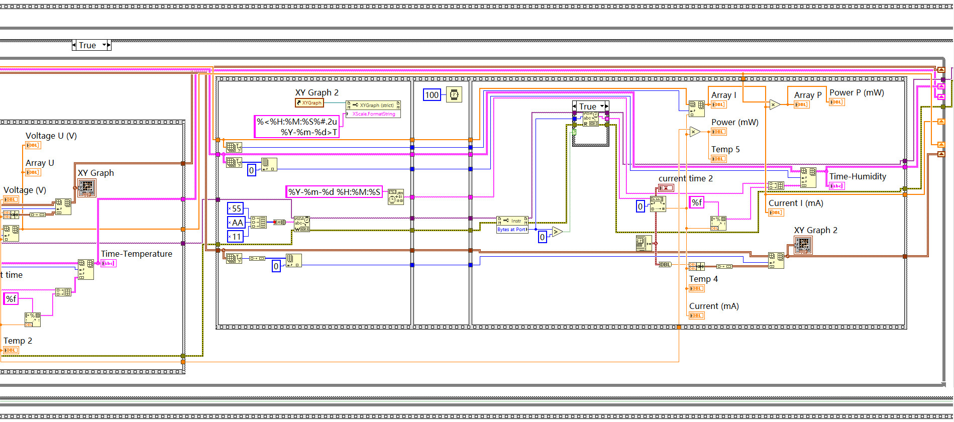
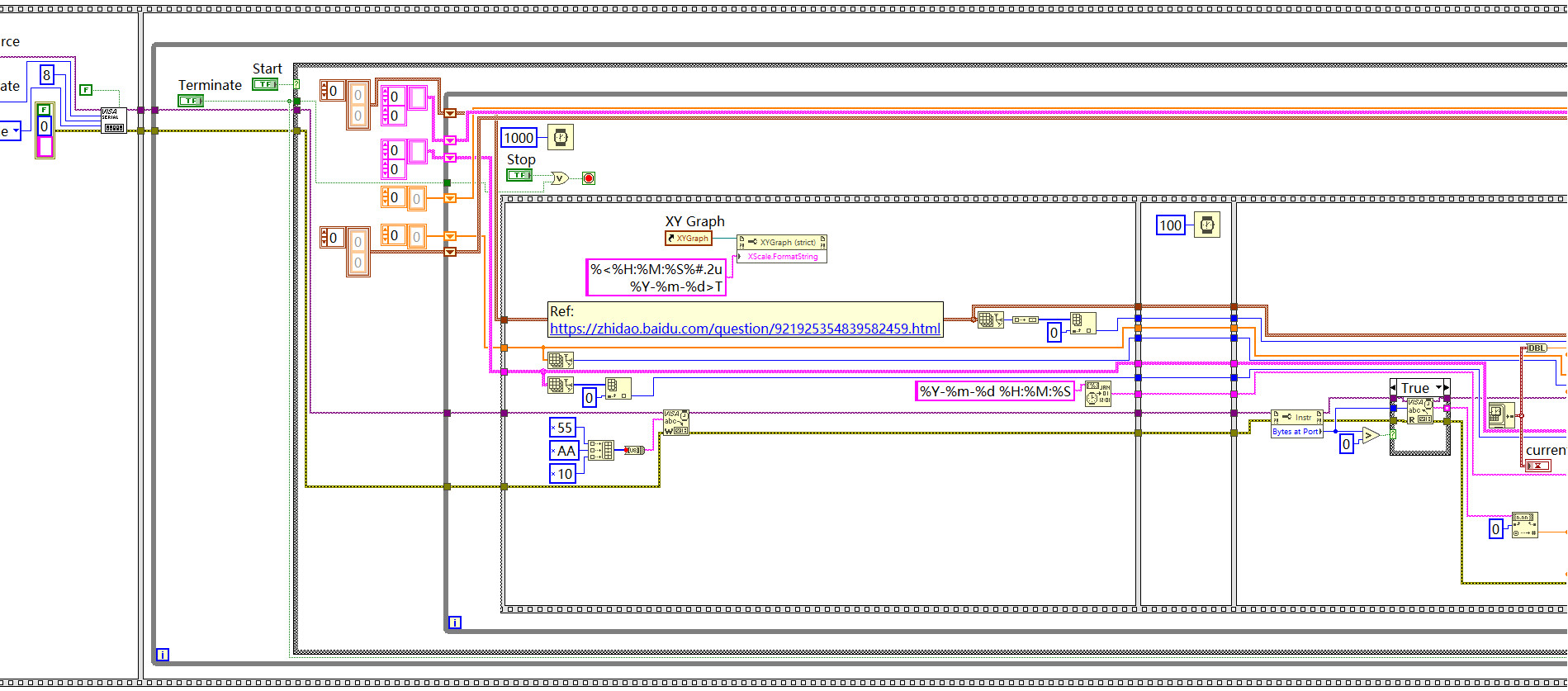
程序框图
Page 1
Page 2
效果
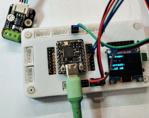
OLED 显示
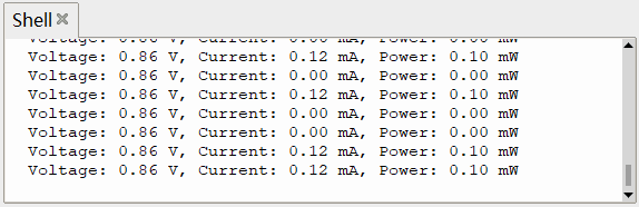
终端打印
测量电机功率
在完成空载情况下功率测量的基础上,考虑加负载的情况。
负载可以是功率器件、电阻、电机等,可以较为明显地反映系统功率的变化。
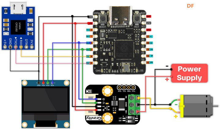
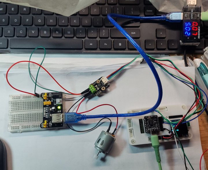
硬件连接
- GP4 ---- SDA (INA219)
- GP5 ---- SCL (INA219)
- GP8 ---- RXD (CH340)
- GP9 ---- TXD (CH340)
- GP4 ---- SDA (OLED_SSD1306)
- GP5 ---- SCL (OLED_SSD1306)
- GND (INA219) ---- Negative (Motor) ---- Negative (Power Supply)
- IN+ (INA219) ---- Positive (Power Supply)
- IN- (INA219) ---- Positive (Motor)
实物连接
通过对比供电接口处的电压和电流值,INA219传感器可以获得更精确的功率值。
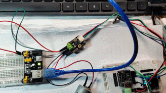
动态演示
LabVIEW 上位机演示
演示了开启电机瞬间的电压、电流以及功率的变化情况。
分析
可以看出,直接采集 INA219 传感器获取的数据存在较大的抖动,可采取 滤波算法 (软件滤波、低通滤波、滑动平均等)进行参数优化,使输出功率更为稳定、更符合实际情况。
总结
本文介绍了 DFRobot Beetle RP2350 开发板结合 INA219 模块实现功率计,并通过 LabVIEW 上位机串口采集 INA219 电流、电压、功率数据监测的项目设计,为 Beetle RP2350 开发板的开发设计和产品应用提供了参考。
|


 沪公网安备31011502402448

 置顶卡
置顶卡 变色卡
变色卡 千斤顶
千斤顶


