像素范,蓝牙播放器。比心
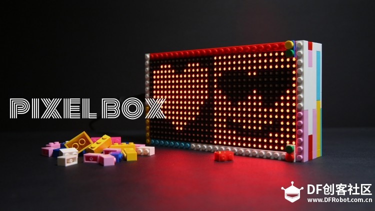
当你的男神/女神答应和你愉快的约会,是不是心脏都激动无比。
然后迷之微笑的开始筹划美好的一天。于是乎想着送个什么了
像素,我的理解:色彩、颗粒............sony大电影《像素大战》
喜欢一个人的纯粹、天真

色彩的第一反应是点阵屏(比如32x16 RGB LED Matrix )
颗粒、颗粒,不就是乐高颗粒吗?
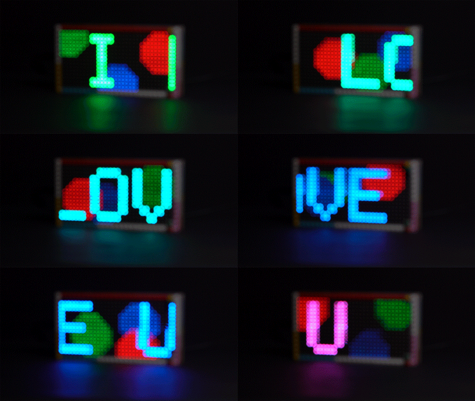
除了情人节表白利器,还是个带音乐频谱的蓝牙播放器
准备材料清单:
. 32x16 RGB LED Matrix 点阵屏
. DFRduino Mega2560 V3.0控制器
. 蓝牙音频模块
. 无源音箱小喇叭
. I2C颜色识别传感器 - TCS34725 (可选)
. 乐高积木颗粒(40粒左右)
电子部分接线:
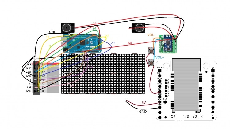
rgb matrix点阵屏的接口有16根接线(R1.G1.B1 R2.G2.B2 A.B.C CLK LAT OE 4个GND),
Arduino mega2560(24.25.26 27.28.29 A4.A1.A2 11 A3 9). 蓝牙音频板包括左右声道接2个小喇叭,
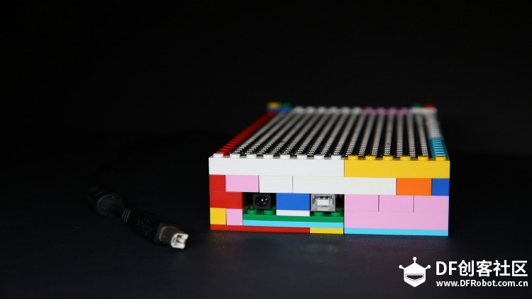
蓝牙音频板还包括音量+、音量-等等功能按钮。可以连接几个4脚按键,最后电源可以自己加入锂电独立供电,也
可以外部usb和dc直流插头供电(如下图)。
在你的理解中,一段音乐是什么呢?
或者说声音是什么,比较直观的就是一堆上下起伏的波(波里面包含很多信息,所以看起来比较杂乱)
更加形象的理解是:五线谱的乐符
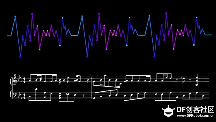
我们如何分析 形象化的表现音乐了,下面来学习音频的快速傅里叶变换(FFT):
"你眼中看似落叶纷飞变化无常的世界,实际只是躺在上帝怀中一份早已谱好的乐章“
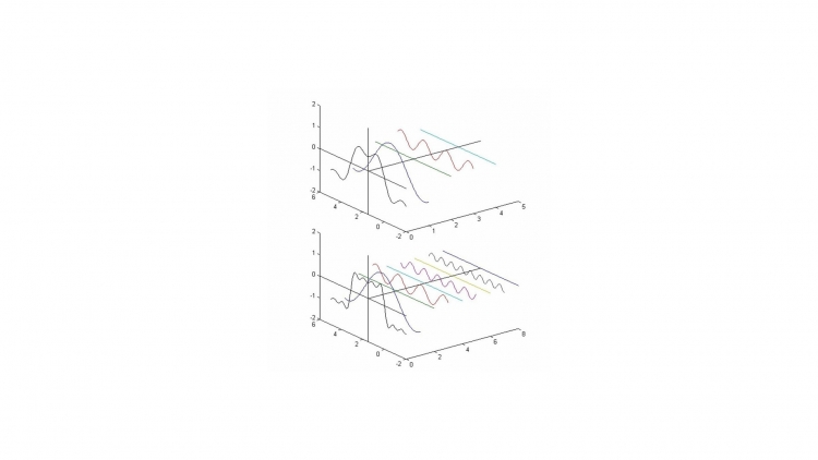
抱歉,这不是一句鸡汤文,而是黑板上确凿的公式:傅里叶同学告诉我们,任何周期函数,都可以看作是不同振幅,不同相位正弦波的叠加。在第一个例子里我们可以理解为,利用对不同琴键不同力度,不同时间点的敲击,可以组合出任何一首乐曲。
而贯穿时域与频域的方法之一,就是传中说的傅里叶分析。傅里叶分析可分为傅里叶级数(Fourier Serie)和傅里叶变换(Fourier Transformation),我们从简单的开始谈起

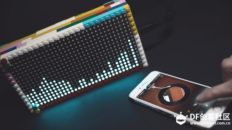
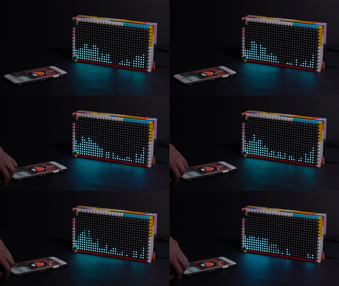
音乐播放情景:音乐在32个频域上的幅度显示
音频.c代码:
- #define LOG_OUT 1 // use the log output function
- #define FFT_N 256 // FFT采样数:16.32.64.128.256
- //#define DEBUG
- #include <FFT.h> //快速傅里叶转换头文件声明
- #include <Adafruit_GFX.h> // Core graphics library
- #include <RGBmatrixPanel.h> // Hardware-specific library
-
- #define Cycle 3 //因为单次采样会有极大的噪音干扰,故用多次采样取平均值的方法
- #define SIZE_WIDTH 32 //rgb显示宽度
- //#define MAX_SPECTRUM 32
- #define GAIN 2.3
- //#define FREQUENCY_INDEX(I) ((I)*3 + 10)
- int Spectrum[SIZE_WIDTH];//数组记录多次采样值并在最后取平均数
- // Similar to F(), but for PROGMEM string pointers rather than literals
- //#define F2(progmem_ptr) (const __FlashStringHelper *)progmem_ptr
- #define CLK 11 // MUST be on PORTB! (Use pin 11 on Mega)
- #define LAT A3
- #define OE 9
- #define A A4
- #define B A1
- #define C A2
- RGBmatrixPanel matrix(A, B, C, CLK, LAT, OE, false);
- const unsigned char myBitmap [] PROGMEM = {
- // 'Designbolts-Free-Valentine-Heart-Heart, 16x16px
- 0x00, 0x00, 0x1c, 0x38, 0x7e, 0x7e, 0x7f, 0xfe, 0x7f, 0xfe, 0x7f, 0xfe, 0x7f, 0xfe, 0x7f, 0xfe,
- 0x3f, 0xfc, 0x1f, 0xf8, 0x1f, 0xf8, 0x0f, 0xf0, 0x03, 0xc0, 0x01, 0x80, 0x00, 0x00, 0x00, 0x00,
- };
- void setup() {
- Serial.begin(115200); // use the serial port
- TIMSK0 = 0; // turn off timer0 for lower jitter - delay() and millis() killed
- ADCSRA = 0xe5; // set the adc to free running mode
- ADMUX = 0x40; // use adc0
- DIDR0 = 0x01; // turn off the digital input for adc0
-
- matrix.begin();
- // matrix.fillScreen(matrix.Color888(0, 150, 255));
- //while(true);
- }
-
- void loop() {
- int ave;
- // matrix.fillScreen(0);
- for (int m=0;m<SIZE_WIDTH;m++){
- Spectrum[m]=0;
- }
- for (int n=0;n<Cycle;n++){ //n记录采样次数
- //while(1) { // reduces jitter
- for (int i = 0 ; i < 512 ; i += 2) { // save 256 samples
- // cli(); // UDRE interrupt slows this way down on arduino1.0
- while(!(ADCSRA & 0x10)); // wait for adc to be ready
- ADCSRA = 0xf5; // restart adc
- byte m = ADCL; // fetch adc data
- byte j = ADCH;
- int k = (j << 8) | m; // form into an int
- k -= 0x0200; // form into a signed int
- k <<= 6; // form into a 16b signed int
- fft_input<i> = k; // put real data into even bins
- fft_input[i+1] = 0; // set odd bins to 0
- }
- // sei(); // turn interrupts back on
- // window data, then reorder, then run, then take output
- fft_window(); // window the data for better frequency response
- fft_reorder(); // reorder the data before doing the fft
- fft_run(); // process the data in the fft
- fft_mag_log(); // take the output of the fft
- /* for (byte i = 0 ; i < FFT_N/2 ; i++)
- {
- Serial.println(fft_log_out<i>); // <--输出到串口
- }*/
- //Serial.write(255); // send a start byte
- //Serial.write(fft_log_out, 128); // send out the data
- }
-
-
-
- static int times = 0;
-
- if(times++ == 0){
- times=0;
- for(int m=0;m<SIZE_WIDTH;m++){
- ave=0;
- for (byte i=m*4;i<(m+1)*4;i++){
- ave+=fft_log_out<i>;
- }
- ave/=4;
- ave/=2;
- Spectrum[m]=ave;
- Spectrum[m]/=Cycle;
- Serial.print(Spectrum[m]);
- Serial.print("-");
- if (m ==15)
- {
- Serial.println("||");
- }
-
- Spectrum[0] = Spectrum[1]-22;
- //Spectrum[1] = Spectrum[1]-7;
- //Spectrum[2] = Spectrum[2]-6;
- //Spectrum[3] = Spectrum[3]-6;
-
-
- int y = Spectrum[m]-8;
- if(y>26)
- y = 15;
-
- /*if(y<=7){
-
- //y = 0;
- matrix.fillScreen(0);
- }*/
-
- matrix.drawLine(m, 0, m, y, matrix.Color888(0, 150, 255));
- matrix.drawLine(m, y+1, m, 15, matrix.Color888(0, 0, 0));
- }
- }
-
- }</i></i></i>
如何制作表情(图形)?

取模软件:
http://javl.github.io/image2cpp/点击进入
选择我们绘制好的图形,更改设置和预览
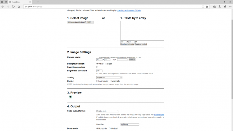
最后设置数据输出格式和绘制模式(水平或者垂直)
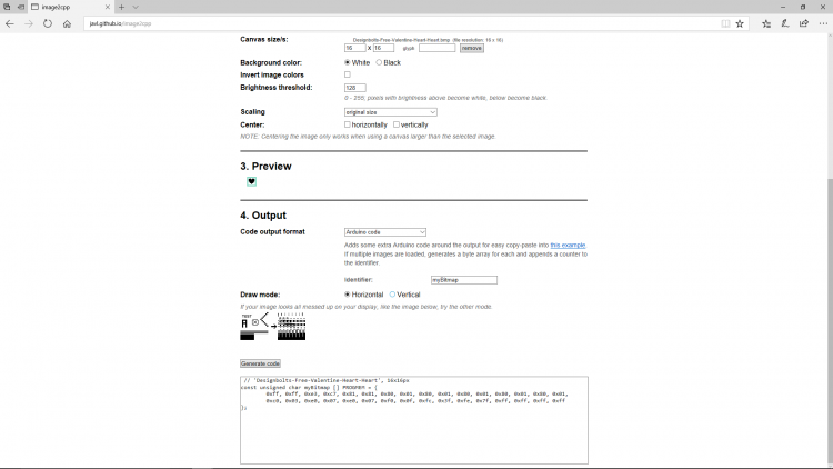
数据格式一般都是一下:
- // 'Designbolts-Free-Valentine-Heart-Heart', 16x16px
- const unsigned char myBitmap [] PROGMEM = {
- 0xff, 0xff, 0xe3, 0xc7, 0x81, 0x81, 0x80, 0x01, 0x80, 0x01, 0x80, 0x01, 0x80, 0x01, 0x80, 0x01,
- 0xc0, 0x03, 0xe0, 0x07, 0xe0, 0x07, 0xf0, 0x0f, 0xfc, 0x3f, 0xfe, 0x7f, 0xff, 0xff, 0xff, 0xff
- };
表情情景演示:
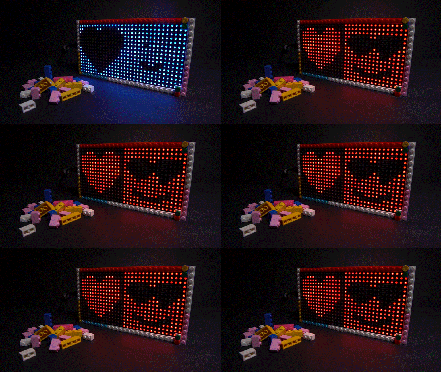
表情.c代码:
- #include <Adafruit_GFX.h>
- #include <Adafruit_SPITFT.h>
- #include <Adafruit_SPITFT_Macros.h>
- #include <gfxfont.h>
-
- // testshapes demo for Adafruit RGBmatrixPanel library.
- // Demonstrates the drawing abilities of the RGBmatrixPanel library.
- // For 16x32 RGB LED matrix:
- // <a href="http://www.adafruit.com/products/420" target="_blank">http://www.adafruit.com/products/420</a>
-
- // Written by Limor Fried/Ladyada & Phil Burgess/PaintYourDragon
- // for Adafruit Industries.
- // BSD license, all text above must be included in any redistribution.
-
-
- #include <RGBmatrixPanel.h> // Hardware-specific library
-
- #define CLK 11 // MUST be on PORTB! (Use pin 11 on Mega)
- #define LAT A4
- #define OE 9
- #define A A0
- #define B A1
- #define C A2
- RGBmatrixPanel matrix(A, B, C, CLK, LAT, OE, false);
- // 'Designbolts-Free-Valentine-Heart-Heart', 16x16px
- const unsigned char myBitmap [] PROGMEM = {
- 0xff, 0xff, 0xe3, 0xc7, 0x81, 0x81, 0x80, 0x01, 0x80, 0x01, 0x80, 0x01, 0x80, 0x01, 0x80, 0x01,
- 0xc0, 0x03, 0xe0, 0x07, 0xe0, 0x07, 0xf0, 0x0f, 0xfc, 0x3f, 0xfe, 0x7f, 0xff, 0xff, 0xff, 0xff
- };
-
- void setup() {
-
- matrix.begin();
- matrix.drawBitmap(0,0,myBitmap,16,16,0xff);
-
- }
-
- void loop() {
- // do nothing
- }
更多玩法...............
加入颜色传感器TCS34725
|


 编辑选择奖
编辑选择奖
 编辑选择奖
编辑选择奖
 沪公网安备31011502402448