项目代码/*
Copyright (c) 2020 Janux
Permission is hereby granted, free of charge, to any person obtaining a copy
of this software and associated documentation files (the "Software"), to deal
in the Software without restriction, including without limitation the rights
to use, copy, modify, merge, publish, distribute, sublicense, and/or sell
copies of the Software, and to permit persons to whom the Software is
furnished to do so, subject to the following conditions:
The above copyright notice and this permission notice shall be included in all
copies or substantial portions of the Software.
THE SOFTWARE IS PROVIDED "AS IS", WITHOUT WARRANTY OF ANY KIND, EXPRESS OR
IMPLIED, INCLUDING BUT NOT LIMITED TO THE WARRANTIES OF MERCHANTABILITY,
FITNESS FOR A PARTICULAR PURPOSE AND NONINFRINGEMENT. IN NO EVENT SHALL THE
AUTHORS OR COPYRIGHT HOLDERS BE LIABLE FOR ANY CLAIM, DAMAGES OR OTHER
LIABILITY, WHETHER IN AN ACTION OF CONTRACT, TORT OR OTHERWISE, ARISING FROM,
OUT OF OR IN CONNECTION WITH THE SOFTWARE OR THE USE OR OTHER DEALINGS IN THE
SOFTWARE.
Based on an original project for the MAX72xx LED matrix and FFT lib made from Shajeeb.
Configuration settings section based on work of Ragnar Ranøyen Homb from Norvegian Creation.
*/
#define LIN_OUT 1 //FHT linear output magnitude
#define FHT_N 128 //set SAMPLES for FHT, Must be a power of 2
#include <FHT.h>
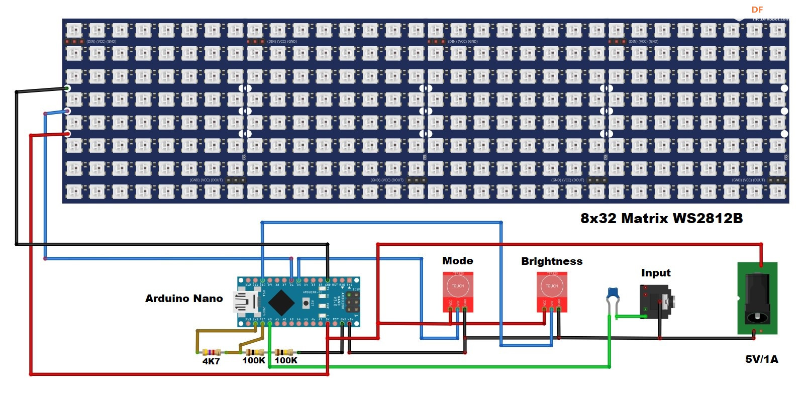
#define xres 32 //Total number of columns in the display, must be <= SAMPLES/2
#define yres 8 //Total number of rows in the display
#define ledPIN 6 //out pint to control Leds
#define NUM_LEDS (xres * yres) //total leds in Matrix
#include <Adafruit_NeoPixel.h>
#include <Adafruit_NeoMatrix.h>
#define colorPIN 5 //pin to change ledcolor
#define brightnessPIN 10 //pin to change brightness
byte displaycolor = 0; //default color value
byte brightness = 1; //default brightness level
#include <EEPROM.h>
#define CONFIG_START 32 //Memory start location
#define CONFIG_VERSION "VER01" //Config version configuration
typedef struct {
char version[6];
byte displaycolor;
byte brightness;
} configuration_type;
configuration_type CONFIGURATION = {
CONFIG_VERSION,
displaycolor,
brightness
};
byte yvalue;
int peaks[xres];
byte state = HIGH; // the current reading from the input pin
byte previousState = LOW; // the previous reading from the input pin
unsigned long lastDebounceTime = 0; // the last time the output pin was toggled
unsigned long debounceDelay = 100; // the debounce time; increase if the output flickers
byte data_avgs[xres]; //Array for samplig
// Parameter 1 = number of leds in matrix
// Parameter 2 = pin number
// Parameter 3 = pixel type flags, add together as needed:
// NEO_KHZ800 800 KHz bitstream (most NeoPixel products w/WS2812 LEDs)
// NEO_KHZ400 400 KHz (classic 'v1' (not v2) FLORA pixels, WS2811 drivers)
// NEO_GRB Pixels are wired for GRB bitstream (most NeoPixel products)
// NEO_RGB Pixels are wired for RGB bitstream (v1 FLORA pixels, not v2)
Adafruit_NeoPixel pixel = Adafruit_NeoPixel(NUM_LEDS, ledPIN, NEO_GRB + NEO_KHZ800);
// EQ filter
byte eq[32] = {
60, 65, 70, 75, 80, 85, 90, 95,
100, 100, 100, 100, 100, 100, 100, 100,
100, 100, 100, 100, 100, 100, 100, 100,
115, 125, 140, 160, 185, 200, 200, 200
};
bool EQ_ON = true; // set to false to disable eq
//Define 5 set of colors for leds, 0 for single custom color
byte colors[][8] = {
{170, 160, 150, 140, 130, 120, 1, 1},
{1, 5, 10, 15, 20, 25, 90, 90},
{90, 85, 80, 75, 70, 65, 1, 1},
{90, 90, 90, 30, 30, 30, 1, 1},
{170, 160, 150, 140, 130, 120, 110, 0}
};
//Define chars for display settings
byte charBitmap[] = {
0x1C, 0x10, 0x10, 0x10, 0x10, 0x1C, 0x08, 0x18, 0x08, 0x08, 0x08, 0x1C,
0x0C, 0x12, 0x04, 0x08, 0x10, 0x1E, 0x0C, 0x12, 0x02, 0x06, 0x12, 0x0C,
0x10, 0x10, 0x10, 0x14, 0x1E, 0x04, 0x1E, 0x10, 0x1E, 0x02, 0x12, 0x0C,
0x1E, 0x10, 0x10, 0x1E, 0x12, 0x1E, 0x1E, 0x02, 0x04, 0x08, 0x08, 0x08,
0x0C, 0x12, 0x0C, 0x12, 0x12, 0x0C, 0x1C, 0x12, 0x1C, 0x12, 0x12, 0x1C
};
void setup() {
pixel.begin(); //initialize Led Matrix
//Begin FFT operations
ADCSRA = 0b11100101; // set ADC to free running mode and set pre-scaler to 32 (0xe5)
ADMUX = 0b00000000; // use pin A0 and external voltage reference
// Read config data from EEPROM
if (loadConfig()) {
displaycolor = CONFIGURATION.displaycolor;
brightness = CONFIGURATION.brightness;
}
//Set brightness loaded from EEPROM
pixel.setBrightness(brightness * 24 + 8);
//Show current config on start
//change true to false if you don't want this
showSettings(3, true);
}
void loop() {
while (1) { // reduces jitter
Sampling(); // FHT Library use only one data array
RearrangeFHT(); // re-arrange FHT result to match with no. of display columns
SendToDisplay(); // send to display according measured value
colorChange(); // check if button pressed to change color
brightnessChange(); // check if button pressed to change brightness
delay(10); // delay to reduce flickering (FHT is too fast :D)
}
}
void Sampling() {
for (int i = 0; i < FHT_N; i++) {
while (!(ADCSRA & 0x10)); // wait for ADC to complete current conversion ie ADIF bit set
ADCSRA = 0b11110101 ; // clear ADIF bit so that ADC can do next operation (0xf5)
//ADLAR bit is 0, so the 10 bits of ADC Data registers are right aligned
byte m = ADCL; // fetch adc data
byte j = ADCH;
int value = (j << 8) | m; // form into an int
value -= 0x0200; // form into a signed int
value <<= 6; // form into a 16b signed int
fht_input[i] = value / 8; // copy to fht input array after compressing
}
// ++ begin FHT data process -+-+--+-+--+-+--+-+--+-+--+-+--+-+-
fht_window(); // window the data for better frequency response
fht_reorder(); // reorder the data before doing the fht
fht_run(); // process the data in the fht
fht_mag_lin(); // take the output of the fht
}
void RearrangeFHT() {
// FHT return real value unsing only one array
// after fht_mag_lin() calling the samples value are in
// the first FHT_N/2 position of the array fht_lin_out[]
int step = (FHT_N / 2) / xres;
int c = 0;
for (int i = 0; i < (FHT_N / 2); i += step) {
data_avgs[c] = 0;
for (int k = 0 ; k < step ; k++) {
data_avgs[c] = data_avgs[c] + fht_lin_out[i + k]; // linear output magnitude
}
data_avgs[c] = data_avgs[c] / step ; // save avgs value
c++;
}
}
void SendToDisplay() {
for (int i = 0; i < xres; i++) {
if (EQ_ON)
data_avgs[i] = data_avgs[i] * (float)(eq[i]) / 100; // apply eq filter
data_avgs[i] = constrain(data_avgs[i], 0, 80); // set max & min values for buckets to 0-80
data_avgs[i] = map(data_avgs[i], 0, 80, 0, yres); // remap averaged values to yres 0-8
yvalue = data_avgs[i];
peaks[i] = peaks[i] - 1; // decay by one light
if (yvalue > peaks[i]) peaks[i] = yvalue; // save peak if > previuos peak
yvalue = peaks[i]; // pick peak to display
setColumn(i, yvalue); // draw columns
}
pixel.show(); // show column
}
// Light up leds of x column according to y value
void setColumn(byte x, byte y) {
int led, i;
for (i = 0; i < yres; i++) {
led = GetLedFromMatrix(x, i); //retrieve current led by x,y coordinates
if (peaks[x] > i) {
switch (displaycolor) {
case 4:
if (colors[displaycolor][i] == 0) {
// show custom color with zero value in array
pixel.setPixelColor(led, 255, 255, 255); //withe
}
else {
// standard color defined in colors array
pixel.setPixelColor(led, Wheel(colors[displaycolor][i]));
}
break;
case 5:
//change color by column
pixel.setPixelColor(led, Wheel(x * 16));
break;
case 6:
//change color by row
pixel.setPixelColor(led, Wheel(i * y * 3));
break;
case 7:
//change color by... country :D
//Italy flagh
//if (x < 11) pixel.setPixelColor(led, 0, 255, 0);
//if (x > 10 && x < 21) pixel.setPixelColor(led, 255, 255, 255);
//if (x > 20) pixel.setPixelColor(led, 255, 0, 0);
//stars and stripes
if (i < yres - 2) {
if (x & 0x01) {
pixel.setPixelColor(led, 0, 0, 255);
}
else {
pixel.setPixelColor(led, 255, 0, 0);
}
}
else {
pixel.setPixelColor(led, 255, 255, 255);
}
break;
default:
//display colors defined in color array
pixel.setPixelColor(led, Wheel(colors[displaycolor][i]));
} //END SWITCH
}
else {
//Light off leds
pixel.setPixelColor(led, pixel.Color(0, 0, 0));
}
}
}
//================================================================
// Calculate a led number by x,y coordinates
// valid for WS2812B with serpentine layout placed in horizzontal
// and zero led at bottom right (DIN connector on the right side)
// input value: x= 0 to xres-1 , y= 0 to yres-1
// return a led number from 0 to NUM_LED
//================================================================
int GetLedFromMatrix(byte x, byte y) {
int led;
x = xres - x - 1;
if (x & 0x01) {
//Odd columns increase backwards
led = ((x + 1) * yres - y - 1);
}
else {
//Even columns increase normally
led = ((x + 1) * yres - yres + y);
}
return constrain(led, 0, NUM_LEDS);
}
//================================================================
void colorChange() {
int reading = digitalRead(colorPIN);
if (reading == HIGH && previousState == LOW && millis() - lastDebounceTime > debounceDelay) {
displaycolor++;
if (displaycolor > 7) displaycolor = 0;
showSettings(1, true); //set to false if you don't want this
saveConfig();
lastDebounceTime = millis();
}
previousState = reading;
}
void brightnessChange() {
int reading = digitalRead(brightnessPIN);
if (reading == HIGH && previousState == LOW && millis() - lastDebounceTime > debounceDelay) {
brightness++;
if (brightness > 7) brightness = 0;
pixel.setBrightness(brightness * 24 + 8);
showSettings(2, true); //set to false if you don't want this
saveConfig();
lastDebounceTime = millis();
}
previousState = reading;
}
// Utility from Adafruit Neopixel demo sketch
// Input a value 0 to 255 to get a color value.
// The colours are a transition R - G - B - back to R.
unsigned long Wheel(byte WheelPos) {
WheelPos = 255 - WheelPos;
if (WheelPos < 85) {
return pixel.Color(255 - WheelPos * 3, 0, WheelPos * 3);
}
if (WheelPos < 170) {
WheelPos -= 85;
return pixel.Color(0, WheelPos * 3, 255 - WheelPos * 3);
}
WheelPos -= 170;
return pixel.Color(WheelPos * 3, 255 - WheelPos * 3, 0);
}
// load whats in EEPROM in to the local CONFIGURATION if it is a valid setting
int loadConfig() {
if (EEPROM.read(CONFIG_START + 0) == CONFIG_VERSION[0] &&
EEPROM.read(CONFIG_START + 1) == CONFIG_VERSION[1] &&
EEPROM.read(CONFIG_START + 2) == CONFIG_VERSION[2] &&
EEPROM.read(CONFIG_START + 3) == CONFIG_VERSION[3] &&
EEPROM.read(CONFIG_START + 4) == CONFIG_VERSION[4]) {
// load (overwrite) the local configuration struct
for (unsigned int i = 0; i < sizeof(CONFIGURATION); i++) {
*((char*)&CONFIGURATION + i) = EEPROM.read(CONFIG_START + i);
}
return 1; // return 1 if config loaded
}
return 0; // return 0 if config NOT loaded
}
// save the CONFIGURATION in to EEPROM
void saveConfig() {
CONFIGURATION.displaycolor = displaycolor;
CONFIGURATION.brightness = brightness;
for (unsigned int i = 0; i < sizeof(CONFIGURATION); i++)
EEPROM.write(CONFIG_START + i, *((char*)&CONFIGURATION + i));
}
// 1 display color level, 2 display brightness level, 3 both
void showSettings(byte num, bool show) {
if (show) {
pixel.clear();
if (num == 1 || num == 3) {
drawChar(0, 0);
drawChar(displaycolor + 1, 5);
}
if (num == 2 || num == 3) {
drawChar(9, xres - 9);
drawChar(brightness + 1, xres - 4);
}
delay(1000);
pixel.clear();
}
}
// Draw custom chars
void drawChar(byte val, byte pos) {
for (int x = 4; x >= 0; x--) {
for (int y = 5; y >= 0; y--) {
if ((charBitmap[val * 6 + 5 - y] >> x) & 0x01) {
pixel.setPixelColor(GetLedFromMatrix(4 - x + pos, y + 1), Wheel((pos > 10) * 170));
pixel.show();
}
}
}
} 复制代码 


 沪公网安备31011502402448
 置顶卡
置顶卡 变色卡
变色卡 千斤顶
千斤顶
 萌萌哒新人
萌萌哒新人
 活跃会员
活跃会员
 宣传大使
宣传大使
 牛X认证
牛X认证
 创作达人
创作达人
 ARD DAY
 摸鱼团员
摸鱼团员
 志“童”道合
 编辑选择奖
编辑选择奖


