项目代码
- //#define CALIBRATE
- //#define GRID // After Calibration this mode should plot a pretty good dot grid on the screen
-
- // See additional calibration comments in the code down by the "#ifdef CALIBRATE"
- // Adjust these values for servo arms in position for state 1 _|
- const double SERVO_LEFT_ZERO = 1600;
- const double SERVO_RIGHT_SCALE = 690; // + makes rotate further left
-
- // Adjust these values for servo arms in position for state 2 |_
- const double SERVO_RIGHT_ZERO = 650;
- const double SERVO_LEFT_SCALE = 650;
-
- #define OPTION_12_HOUR // 12 or comment out this line for 24 hour time
- //#define OPTION_MONTH_DAY // commented out = month/day or uncomment the line for day/month
-
- const double DRAW_DELAY = 5; // 3
-
- ///////////////////////////////////////////////////////////////////////////////
-
- // Plotclock
- // cc - by Johannes Heberlein 2014
- // modified for glow clock - Tucker Shannon 2018
- // improved - 12Me21 2018
-
- // v 1.07ddd
- // thingiverse.com/joo wiki.fablab-nuernberg.de
- // thingiverse.com/TuckerPi
- // units: mm; microseconds; radians
- // origin: bottom left of drawing surface
- // time library see http://playground.arduino.cc/Code/time
- // RTC library see http://playground.arduino.cc/Code/time
- // or http://www.pjrc.com/teensy/td_libs_DS1307RTC.html
- // Change log:
- // 1.01 Release by joo at https://github.com/9a/plotclock
- // 1.02 Additional features implemented by Dave (https://github.com/Dave1001/):
- // - added ability to calibrate servofaktor seperately for left and right servos
- // - added code to support DS1307, DS1337 and DS3231 real time clock chips
- // - see http://www.pjrc.com/teensy/td_libs_DS1307RTC.html for how to hook up the real time clock
- // 1.03 Fixed the length bug at the servoplotclockogp2 angle calculation, other fixups
- // 1.04 Modified for Tuck's glow clock
- // 1.05 Modified calibration mode to draw a 4 point square instead
- // 1.06 Rewrote most of the code, improved calibration, added date drawing, fixed bug in angle calculations, etc.
- // 1.07ddd Reverted code to return it to using the DS1307 Library and removed the long press date code.
- // Did this because I liked this codes calibration code better than the v1.05 calibration code that drew a square.
- // Plus the bug fixes in 1.06 are good
- // Added comments on how to calibrate
- // Split Number drawing and letter drawing into two different functions
- // Improved the letter "I"
-
- ///////////////////////////////////////////////////////////////////////////////
-
- #include <Time.h> // see http://playground.arduino.cc/Code/time
- #include <TimeLib.h>
- #include <Servo.h> //servo controller
- #include <Wire.h>
- #include <DS1307RTC.h> // see http://playground.arduino.cc/Code/time
-
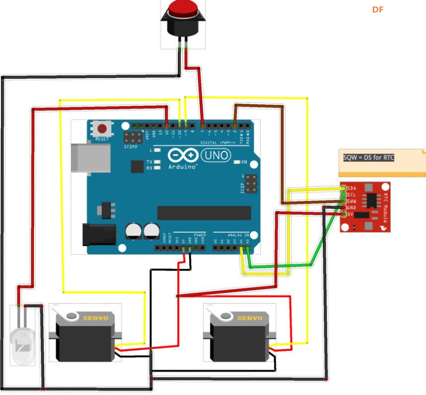
- //pins
- const int SERVO_LEFT_PIN = 6;
- const int SERVO_RIGHT_PIN = 5;
- const int LED_PIN = 12;
- const int BUTTON_PIN = 13;
-
- //Sizes
- const double LOWER_ARM = 35; //servo to lower arm joint
- const double UPPER_ARM_LEFT = 56; //lower arm joint to led
- const double LED_ARM = 13.5; //upper arm joint to led
- const double UPPER_ARM = 45; //lower arm joint to upper arm joint
- double cosineRule(double a, double b, double c);
- const double LED_ANGLE = cosineRule(UPPER_ARM_LEFT,UPPER_ARM,LED_ARM);
-
- //Location of servos relative to origin
- const double SERVO_LEFT_X = 22;
- const double SERVO_LEFT_Y = -32;
- const double SERVO_RIGHT_X = SERVO_LEFT_X + 25.5;
- const double SERVO_RIGHT_Y = SERVO_LEFT_Y;
-
- // lovely macros
- #define radian(angle) (M_PI*2* angle)
- #define dist(x,y) sqrt(sq(x)+sq(y))
- #define angle(x,y) atan2(y,x)
-
- //digit location/size constants
- const double TIME_BOTTOM = 12;
- const double TIME_WIDTH = 11;
- const double TIME_HEIGHT = 18; //16;
-
- const double DAY_WIDTH = 7;
- const double DAY_HEIGHT = 12;
- const double DAY_BOTTOM = 5;
- const double DATE_BOTTOM = 24;
-
- const double HOME_X = 55, HOME_Y = -5;
- Servo servoLeft, servoRight;
-
- // Sunday is the first triple
- const char weekDays[] = {8,10,12, 5,6,12, 9,10,2, 11,2,13, 9,4,10, 3,7,14, 8,1,9}; //character set: AEFHMORSTUWNDI
-
- double lastX = HOME_X, lastY = HOME_Y;
-
- bool lightOn = false;
-
- void setup() {
- pinMode(LED_PIN, OUTPUT);
- digitalWrite(LED_PIN, LOW);
- pinMode(BUTTON_PIN, INPUT_PULLUP);
- }
-
- void light(bool state){
- lightOn = state == HIGH; //I'm *pretty* sure HIGH/LOW are just true/false, but...
- delay(100);
- digitalWrite(LED_PIN, state);
- }
-
- const int LONG_PRESS_DURATION = 750;
-
- void loop(){
- if(digitalRead(BUTTON_PIN) != LOW)
- return;
-
- if (!servoLeft.attached()) servoLeft.attach(SERVO_LEFT_PIN);
- if (!servoRight.attached()) servoRight.attach(SERVO_RIGHT_PIN);
- #ifdef CALIBRATE
- // Pressing the button alternates the servo arms between 2 states.
- // State one if left arm pointing to 9 o'clock and right arm pointing to 12 o'clock _|
- // State two if left arm pointing to 12 o'clock and right arm pointing to 3 o'clock |_
- // At the very top of the code you adjust the 4 constants to get the arms into these exact positions.
- // Adjust SERVO_LEFT_ZERO so that the left servo points to 9 o'clock when in state one
- // Adjust SERVO_RIGHT_SCALE so that the right servo points to 12 o'clock when in state one
-
- // Adjust SERVO_RIGHT_ZERO so that the right servo points to 3 o'clock when in state two
- // Adjust SERVO_LEFT_SCALE so that the left servo points to 12 o'clock when in state two
-
- static bool half;
- servoLeft.writeMicroseconds(floor(SERVO_LEFT_ZERO + (half ? - M_PI/2 : 0) * SERVO_LEFT_SCALE ));
- servoRight.writeMicroseconds(floor(SERVO_RIGHT_ZERO + (half ? 0 : M_PI/2 ) * SERVO_RIGHT_SCALE ));
- light(half ? LOW : HIGH);
- half = !half;
- delay(2000);
- #else //CALIBRATE
- #ifdef GRID
- for(int i = 0; i <= 70; i += 10)
- for(int j = 0; j <= 40; j += 10){
- drawTo(i, j);
- light(HIGH);
- light(LOW);
- }
- #else //GRID
- delay(10); // debounce
- uint32_t longpress = millis() + LONG_PRESS_DURATION;
- while ((!digitalRead(BUTTON_PIN)) && (millis() < longpress))
- { }; // wait
- bool date = false;
- if (millis() >= longpress)
- date = true;
-
- drawTo(HOME_X, 0);
- tmElements_t tm;
- //time_t tt;
- uint8_t dayOfWeek; // 0 = Sunday, 6 = Saturday
- if (RTC.read(tm))
- {
- setTime(tm.Hour,tm.Minute,tm.Second,tm.Day,tm.Month,tm.Year);
- //tt = makeTime(tm); // need a normal time so it can be converted to day of week. Sunday = 1
- dayOfWeek = dayOfWeek(makeTime(tm)) - 1; // the minus 1 normalized so Sunday = 0
- }
- if (date) {
- #ifdef OPTION_MONTH_DAY
- int temp = tm.Day;
- tm.Day = tm.Month;
- tm.Month = temp;
- #endif
- //draw month
- if(tm.Month / 10)
- drawDigit(70-(DAY_WIDTH+3)*5, DATE_BOTTOM, DAY_WIDTH, DAY_HEIGHT, tm.Month / 10);
- drawDigit(70-(DAY_WIDTH+3)*4, DATE_BOTTOM, DAY_WIDTH, DAY_HEIGHT, tm.Month % 10);
- // Draw Slash
- drawDigit(70-(DAY_WIDTH+3)*3, DATE_BOTTOM, DAY_WIDTH, DAY_HEIGHT, 12);
- //day
- if(tm.Day / 10){
- drawDigit(70-(DAY_WIDTH+3)*2, DATE_BOTTOM, DAY_WIDTH, DAY_HEIGHT, tm.Day / 10);
- drawDigit(70-(DAY_WIDTH+3), DATE_BOTTOM, DAY_WIDTH, DAY_HEIGHT, tm.Day % 10);
- }else
- drawDigit(70-(DAY_WIDTH+3)*2, DATE_BOTTOM, DAY_WIDTH, DAY_HEIGHT, tm.Day % 10);
- //weekday
- drawChar(5,DAY_BOTTOM,DAY_WIDTH,DAY_HEIGHT,weekDays[dayOfWeek*3]);
- drawChar(5+DAY_WIDTH+5,DAY_BOTTOM,DAY_WIDTH,DAY_HEIGHT, weekDays[dayOfWeek*3+1]);
- drawChar(5+(DAY_WIDTH+5)*2,DAY_BOTTOM,DAY_WIDTH,DAY_HEIGHT,weekDays[dayOfWeek*3+2]);
-
- } else {
- #ifdef OPTION_12_HOUR
- if(tm.Hour >= 12){
- tm.Hour = tm.Hour - 12;
- // drawDigit(5,35,1,1,10); // Draws a DOT - Not sure why
- }
- if(tm.Hour == 0)
- tm.Hour = 12;
- #endif
- //draw hour
- if(tm.Hour / 10)
- drawDigit(3, TIME_BOTTOM, TIME_WIDTH, TIME_HEIGHT, tm.Hour / 10);
- drawDigit(3+TIME_WIDTH+3, TIME_BOTTOM, TIME_WIDTH, TIME_HEIGHT, tm.Hour % 10);
- // Draw colon
- drawDigit((69-TIME_WIDTH)/2, TIME_BOTTOM, TIME_WIDTH, TIME_HEIGHT, 11);
- //minute
- drawDigit(69-(TIME_WIDTH+3)*2, TIME_BOTTOM, TIME_WIDTH, TIME_HEIGHT, tm.Minute / 10);
- drawDigit(72-(TIME_WIDTH+3), TIME_BOTTOM, TIME_WIDTH, TIME_HEIGHT, tm.Minute % 10);
-
- }
- #endif // NOT CALIBRATE OR GRID
- drawTo(HOME_X, HOME_Y);
- #endif // GRID or Normal Plot Time
- servoLeft.detach();
- servoRight.detach();
- }
-
- #define digitMove(dx, dy) drawTo(x + width*dx, y + height*dy)
- #define digitStart(dx, dy) digitMove(dx, dy); light(HIGH)
- #define digitArc(dx, dy, rx, ry, start, last) drawArc(x + width*dx, y + height*dy, width*rx, height*ry, radian(start), radian(last))
-
- // Symbol is drawn with the lower left corner at (x,y) and a size of (width,height).
- void drawDigit(double x, double y, double width, double height, char digit) {
- //see macros for reference
- switch (digit) {
- case 0: //
- digitStart(1/2,1);
- digitArc(1/2,1/2, 1/2,1/2, 1/4, -3/4);
- //digitStart(1,1/2);
- //digitArc(1/2,1/2, 1/2,1/2, 0, 1.02);
- break;
- case 1: //
- digitStart(1/4,7/8);
- digitMove(1/2,1);
- digitMove(1/2,0);
- break;
- case 2: //
- digitStart(0,3/4);
- digitArc(1/2,3/4, 1/2,1/4, 1/2, -1/8);
- digitArc(1,0, 1,1/2, 3/8, 1/2);
- digitMove(1,0);
- break;
- case 3:
- digitStart(0,3/4);
- digitArc(1/2,3/4, 1/2,1/4, 3/8, -1/4);
- digitArc(1/2,1/4, 1/2,1/4, 1/4, -3/8);
- break;
- case 4:
- digitStart(1,3/8);
- digitMove(0,3/8);
- digitMove(3/4,1);
- digitMove(3/4,0);
- break;
- case 5: //wayy too many damn lines
- digitStart(1,1);
- digitMove(0,1);
- digitMove(0,1/2);
- digitMove(1/2,1/2);
- digitArc(1/2,1/4, 1/2,1/4, 1/4, -1/4);
- digitMove(0,0);
- break;
- case 6:
- digitStart(0,1/4);
- digitArc(1/2,1/4, 1/2,1/4, 1/2, -1/2);
- digitArc(1,1/2, 1,1/2, 1/2, 1/4);
- break;
- case 7:
- digitStart(0,1);
- digitMove(1,1);
- digitMove(1/4,0);
- break;
- case 8:
- digitStart(1/2,1/2);
- digitArc(1/2,3/4, 1/2,1/4, -1/4, 3/4);
- digitArc(1/2,1/4, 1/2,1/4, 1/4, -3/4);
- break;
- case 9:
- digitStart(1,3/4);
- digitArc(1/2,3/4, 1/2,1/4, 0, 1);
- digitMove(3/4,0);
- break;
- case 10: //dot
- digitStart(0,0);
- //digitMove(0,1);
- //digitMove(1,1);
- //digitMove(1,0);
- break;
- case 11: //colon
- digitStart(1/2,3/4);
- light(LOW);
- digitStart(1/2,1/4);
- break;
- case 12: //slash
- digitStart(3/4,5/4);
- digitMove(1/4,-1/4);
- break;
- }
- light(LOW);
- }
-
- void drawChar(double x, double y, double width, double height, char digit) {
- //see macros for reference
- switch (digit) {
- //letters for the day of the week
- case 1: //A
- digitStart(0,0);
- digitMove(1/2,1);
- digitMove(1,0);
- light(LOW);
- digitStart(1/4,1/2);
- digitMove(3/4,1/2);
- break;
- case 2: //E
- digitStart(1,0);
- digitMove(0,0);
- digitMove(0,1);
- digitMove(1,1);
- light(LOW);
- digitStart(0,1/2);
- digitMove(1,1/2);
- break;
- case 3: //F
- digitStart(0,0);
- digitMove(0,1);
- digitMove(1,1);
- light(LOW);
- digitStart(0,1/2);
- digitMove(1,1/2);
- break;
- case 4: //H
- digitStart(0,1);
- digitMove(0,0);
- light(LOW);
- digitStart(0,1/2);
- digitMove(1,1/2);
- light(LOW);
- digitStart(1,1);
- digitMove(1,0);
- break;
- case 5: //M
- digitStart(0,0);
- digitMove(0,1);
- digitMove(1/2,1/2);
- digitMove(1,1);
- digitMove(1,0);
- break;
- case 6: //O (0)
- digitStart(1,1/2);
- digitArc(1/2,1/2, 1/2,1/2, 0, 1.02);
- break;
- case 7: //R
- digitStart(0,0);
- digitMove(0,1);
- digitMove(1/2,1);
- digitArc(1/2,3/4, 1/2,1/4, 1/4, -1/4);
- digitMove(0,1/2);
- digitMove(1,0);
- break;
- case 8: //S
- digitStart(0,0);
- digitMove(1/2,0);
- digitArc(1/2,1/4, 1/2,1/4, -1/4, 1/4);
- digitArc(1/2,3/4, 1/2,1/4, 3/4, 1/4);
- digitMove(1,1);
- break;
- case 9: //T
- digitStart(1,1);
- digitMove(-1/2,1); //bad
- light(LOW);
- digitStart(1/2,1);
- digitMove(1/2,0);
- break;
- case 10: //U
- digitStart(0,1);
- digitMove(0,1/4);
- digitArc(1/2,1/4, 1/2,1/4, -1/2, 0);
- digitMove(1,1);
- break;
- case 11: //W
- digitStart(0,1);
- digitMove(0,0);
- digitMove(1/2,1/2);
- digitMove(1,0);
- digitMove(1,1);
- break;
- case 12: //N
- digitStart(0,0);
- digitMove(0,1);
- digitMove(1,0);
- digitMove(1,1);
- break;
- case 13: //D
- digitStart(0,0);
- digitMove(0,1);
- digitMove(1/2,1);
- digitArc(1/2,1/2, 1/2,1/2, 1/4,-1/4);
- digitMove(0,0);
- break;
- case 14: //I
- digitStart(1/2,1);
- digitMove(1/2,0);
- light(LOW);
- digitStart(0,0);
- digitMove(1,0);
- light(LOW);
- digitStart(1,1);
- digitMove(0,1);
- break;
- }
- light(LOW);
- }
-
- #define ARCSTEP 0.05 //0.05 //should change depending on radius...
- void drawArc(double x, double y, double rx, double ry, double pos, double last) {
- if(pos < last)
- for(; pos <= last; pos += ARCSTEP)
- drawTo(x + cos(pos)*rx, y + sin(pos)*ry);
- else
- for(; pos >= last; pos -= ARCSTEP)
- drawTo(x + cos(pos)*rx, y + sin(pos)*ry);
- }
-
- //didn't really change this
- void drawTo(double pX, double pY) {
- double dx, dy, c;
- int i;
-
- // dx dy of new point
- dx = pX - lastX;
- dy = pY - lastY;
- //path length in mm, times 4 equals 4 steps per mm
- c = floor(4 * dist(dx,dy));
-
- if (c < 1)
- c = 1;
-
- // draw line point by point
- for (i = 1; i <= c; i++){
- set_XY(lastX + (i * dx / c), lastY + (i * dy / c));
- if (lightOn)
- delay(DRAW_DELAY);
- }
-
- lastX = pX;
- lastY = pY;
- }
-
- // cosine rule for angle between c and a
- double cosineRule(double a, double b, double c) {
- return acos((sq(a)+sq(c)-sq(b))/(2*a*c));
- }
-
- void set_XY(double x, double y) {
- //Calculate triangle between left servo, left arm joint, and light
- //Position of pen relative to left servo
- //rectangular
- double penX = x - SERVO_LEFT_X;
- double penY = y - SERVO_LEFT_Y;
- //polar
- double penAngle = angle(penX,penY);
- double penDist = dist(penX,penY);
- //get angle between lower arm and a line connecting the left servo and the pen
- double bottomAngle = cosineRule(LOWER_ARM, UPPER_ARM_LEFT, penDist);
-
- servoLeft.writeMicroseconds(floor(SERVO_LEFT_ZERO + (bottomAngle + penAngle - M_PI) * SERVO_LEFT_SCALE));
-
- //calculate middle arm joint location
- double topAngle = cosineRule(UPPER_ARM_LEFT, LOWER_ARM, penDist);
- double lightAngle = penAngle - topAngle + LED_ANGLE + M_PI;
- double jointX = x - SERVO_RIGHT_X + cos(lightAngle) * LED_ARM;
- double jointY = y - SERVO_RIGHT_Y + sin(lightAngle) * LED_ARM;
-
- bottomAngle = cosineRule(LOWER_ARM, UPPER_ARM, dist(jointX, jointY));
- double jointAngle = angle(jointX, jointY);
-
- servoRight.writeMicroseconds(floor(SERVO_RIGHT_ZERO + (jointAngle - bottomAngle) * SERVO_RIGHT_SCALE));
- }
|


 沪公网安备31011502402448
 置顶卡
置顶卡 变色卡
变色卡 千斤顶
千斤顶
 萌萌哒新人
萌萌哒新人
 活跃会员
活跃会员
 宣传大使
宣传大使
 牛X认证
牛X认证
 创作达人
创作达人
 ARD DAY
 摸鱼团员
摸鱼团员
 志“童”道合
 编辑选择奖
编辑选择奖


