项目代码
- #include <Adafruit_GFX.h>
- #include <Adafruit_GrayOLED.h>
- #include <Adafruit_SPITFT.h>
- #include <Adafruit_SPITFT_Macros.h>
- #include <gfxfont.h>
-
- /**
- _ _____ ___ ___ _ _ _ __ ___ _ _
- / \ |___ / _ \ / _ \ / \ _ _ __| (_) __\ \ / (_)___ _ _ __ _| (_)_______ _ __
- / _ \ / / | | | | | |_____ / _ \| | | |/ _` | |/ _ \ \ / /| / __| | | |/ _` | | |_ / _ \ '__|
- / ___ \ / /| |_| | |_| |_____/ ___ \ |_| | (_| | | (_) \ V / | \__ \ |_| | (_| | | |/ / __/ |Twin
- /_/ \_\/_/ \___/ \___/ /_/ \_\__,_|\__,_|_|\___/ \_/ |_|___/\__,_|\__,_|_|_/___\___|_|Display
- with optional added Neopixel matrix
-
- ReVox A700 AudioVisualizer
- Copyright (C) 2021 by DIYLAB <https://www.diylab.de> GitHub: <https://github.com/DIYLAB-DE/AudioVisualizer>
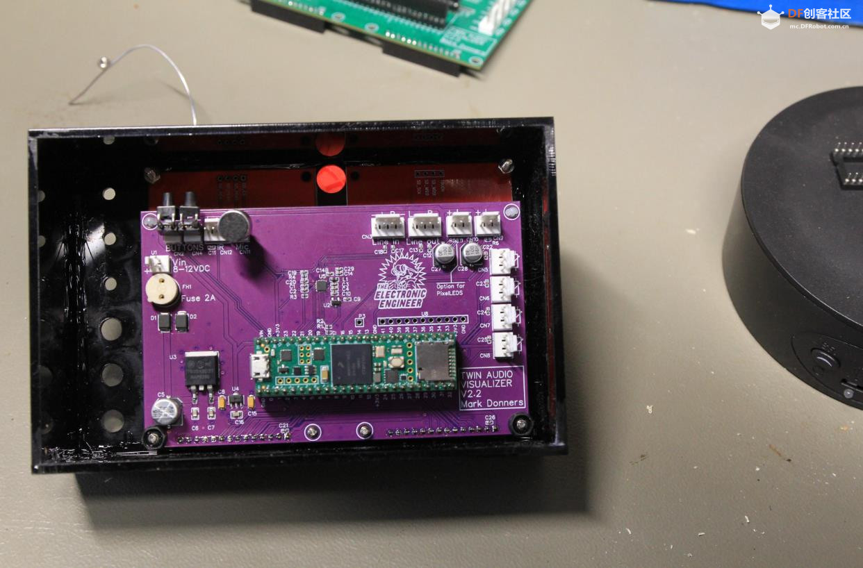
- Modification for Dual Display and pixelleds done by Mark Donners, TheElectronicEngineer.nl
- ~~~~~~~~~~~~~~~~~~~~~~~~~~~~~~~~~~~~~~~~~~~~~~~~~~~~~~~~~~~~~~~~~~~~~~~~~~~~~~~~~~~~~~~~~~~~~~~~
- This Software is free software: you can redistribute it and/or modify it under the terms of the
- GNU General Public License as published by the Free Software Foundation, either version 3 of the
- License, or (at your option) any later version.
-
- This Software is distributed in the hope that it will be useful, but WITHOUT ANY WARRANTY;
- without even the implied warranty of MERCHANTABILITY or FITNESS FOR A PARTICULAR PURPOSE.
- See the GNU General Public License for more details: <http://www.gnu.org/licenses/>
-
- ~~~~~~~~~~~~~~~~~~~~~~~~~~~~~~~~~~~~~~~~~~~~~~~~~~~~~~~~~~~~~~~~~~~~~~~~~~~~~~~~~~~~~~~~~~~~~~~~
- !!! IMPORTANT !!!
- The GNU General Public License (GNU GPL) obligates the user to also place the software under the
- conditions of the GPL (copyleft) when redistributing the software in its original or modified form
- (so-called derivative works). If the licensee does not comply with the conditions, the right to free use expires retroactively!
- Therefore, the user is also required to make the source code available and to subject the derived software to the GPL.
- ~~~~~~~~~~~~~~~~~~~~~~~~~~~~~~~~~~~~~~~~~~~~~~~~~~~~~~~~~~~~~~~~~~~~~~~~~~~~~~~~~~~~~~~~~~~~~~~~
- !!! WICHTIG !!!
- Die GNU General Public License (GNU GPL) verpflichtet den Nutzer dazu, bei Weiterverbreitung der Software
- in ihrer ursprünglichen oder veränderten Form (sog. abgeleitete Werke), diese ebenfalls unter die Bedingungen der GPL zu stellen (Copyleft).
- Hält sich der Lizenznehmer nicht an die Bedingungen, erlischt die Befugnis zur freien Benutzung rückwirkend!
- Daher ist der Verwender gehalten, ebenfalls den Quellcode zugänglich zu machen und die abgeleitete Software wiederum der GPL zu unterwerfen.
- ~~~~~~~~~~~~~~~~~~~~~~~~~~~~~~~~~~~~~~~~~~~~~~~~~~~~~~~~~~~~~~~~~~~~~~~~~~~~~~~~~~~~~~~~~~~~~~~~
-
- Special thanks to Bodmer <https://github.com/Bodmer> for the AA drawing routines and the rainbow colors!
-
- Used libraries
- ---------------
- Optimized ILI9341 screen driver library for Teensy 4/4.1, with vsync and differential updates: <https://github.com/vindar/ILI9341_T4>
- TGX - a tiny/teensy graphics library: <https://github.com/vindar/tgx>
- Arduino OneButton Library: <https://github.com/mathertel/OneButton> (install via the Arduino library manager)
- IRremote Arduino Library: <https://github.com/Arduino-IRremote/Arduino-IRremote>
- TeensyID: https://github.com/sstaub/TeensyID
-
- Used development software
- -------------------------
- Arduino IDE 1.8.19
- Teensyduino, Version 1.56
-
-
-
- /**************************************************************************************************
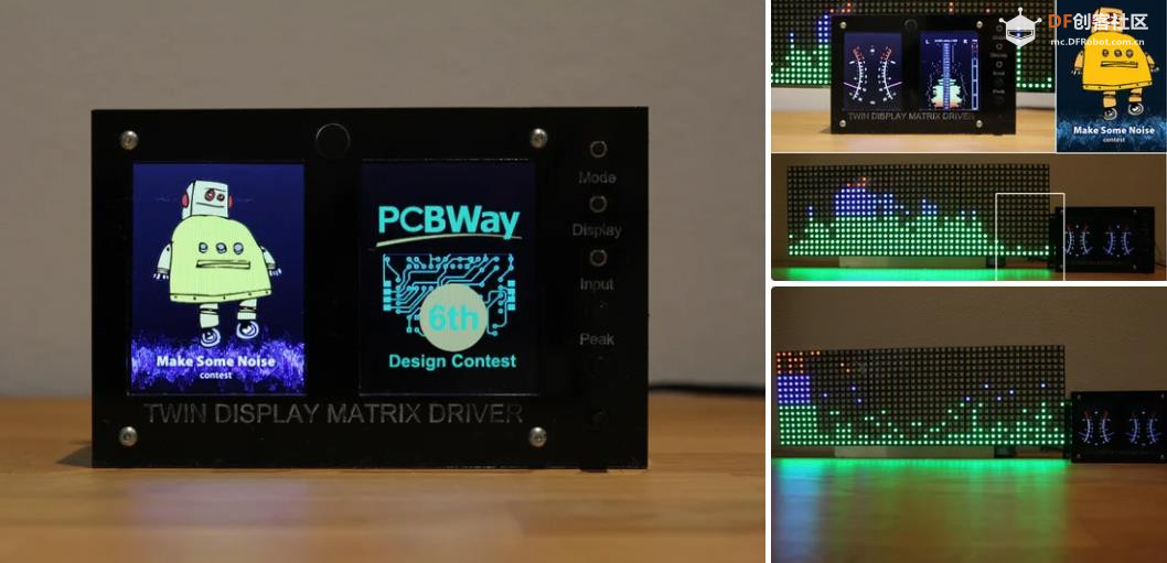
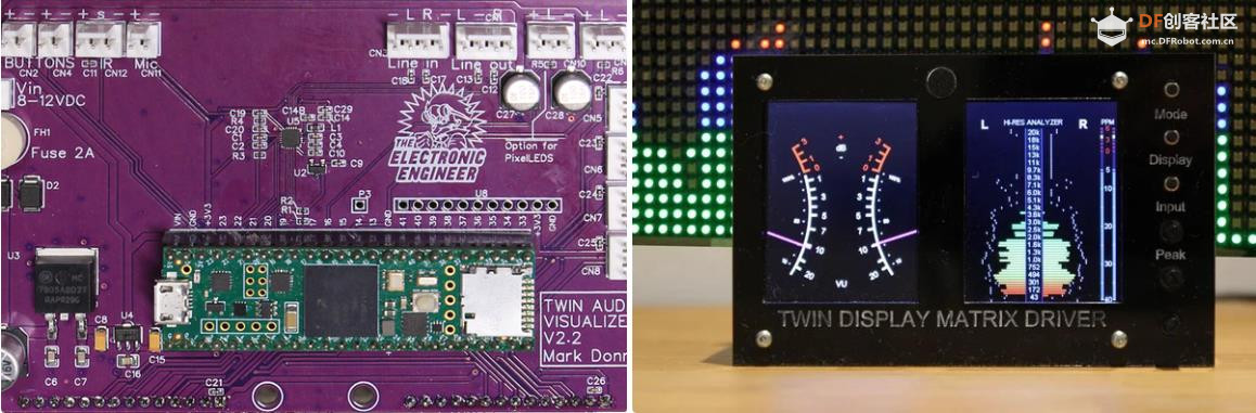
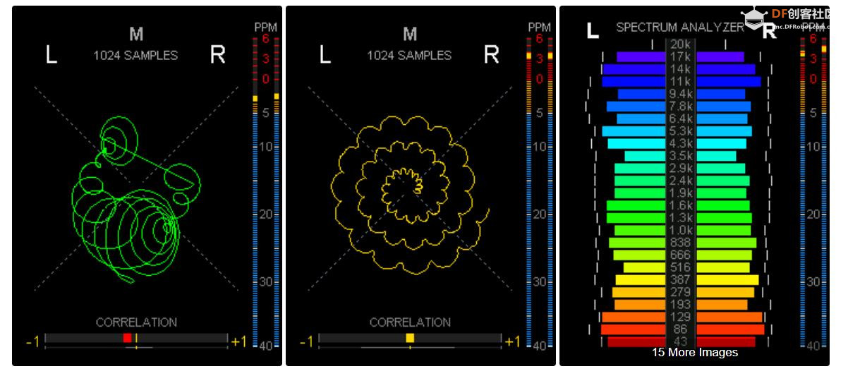
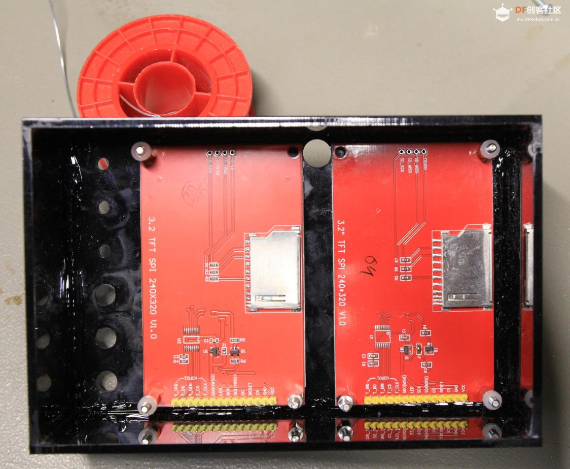
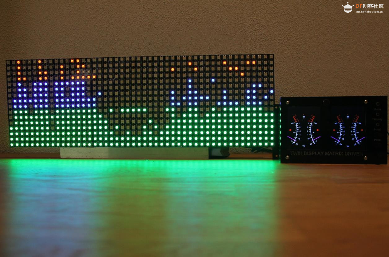
- Updated to version for 2 displays. The function of the first display is unchanged, compared to
- the orignal firmware. the second display will always show Stereo Analog VU meter
- Also implemented extra button to switch between line and mic input
-
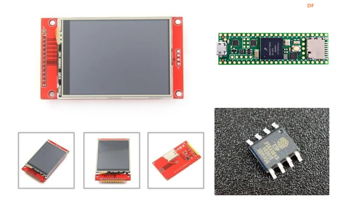
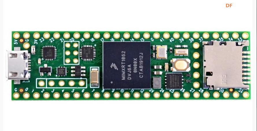
- Take Note: For this sketch to work, you will need Arduino 4.1 with added EXTERNAL PSRAM
-
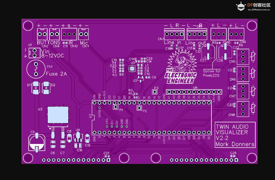
- This update will include Pixelled matrix and potmeters to adjust sensitivity
- Compared to the original version 2.0.1, the folowing files where changed:
- AudioVisualizer, Analog, Gfx
- Logo.h, was added
-
- I did a succesful compilation using the following library versions:
- Using library Wire at version 1.0
- Using library Audio at version 1.3
- Using library SPI at version 1.0
- Using library SD at version 2.0.0
- Using library SdFat at version 2.1.0
- Using library SerialFlash at version 0.5
- Using library ILI9341_T4-main at version 0.1
- Using library tgx-main at version 0.5
- Using library EEPROM at version 2.0
- Using library OneButton at version 2.0.4
- Using library IRremote at version 3.6.1
- Using library TeensyID-main at version 1.3.3
- Using library ILI9488_t3 at version 1.0
-
-
- *************************************************************************************************/
-
- //////////////////////////////////////////////////////////////////////////////////////////////////
- // USER CONFIG SECTION (please only edit here!) //
- //////////////////////////////////////////////////////////////////////////////////////////////////
-
- #define VERSION "v4.0, 25.10.2023"
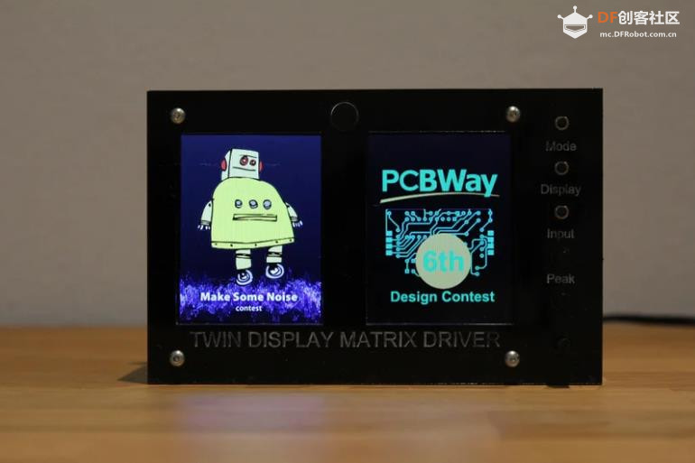
- #define SHOWLOGO true // show logo
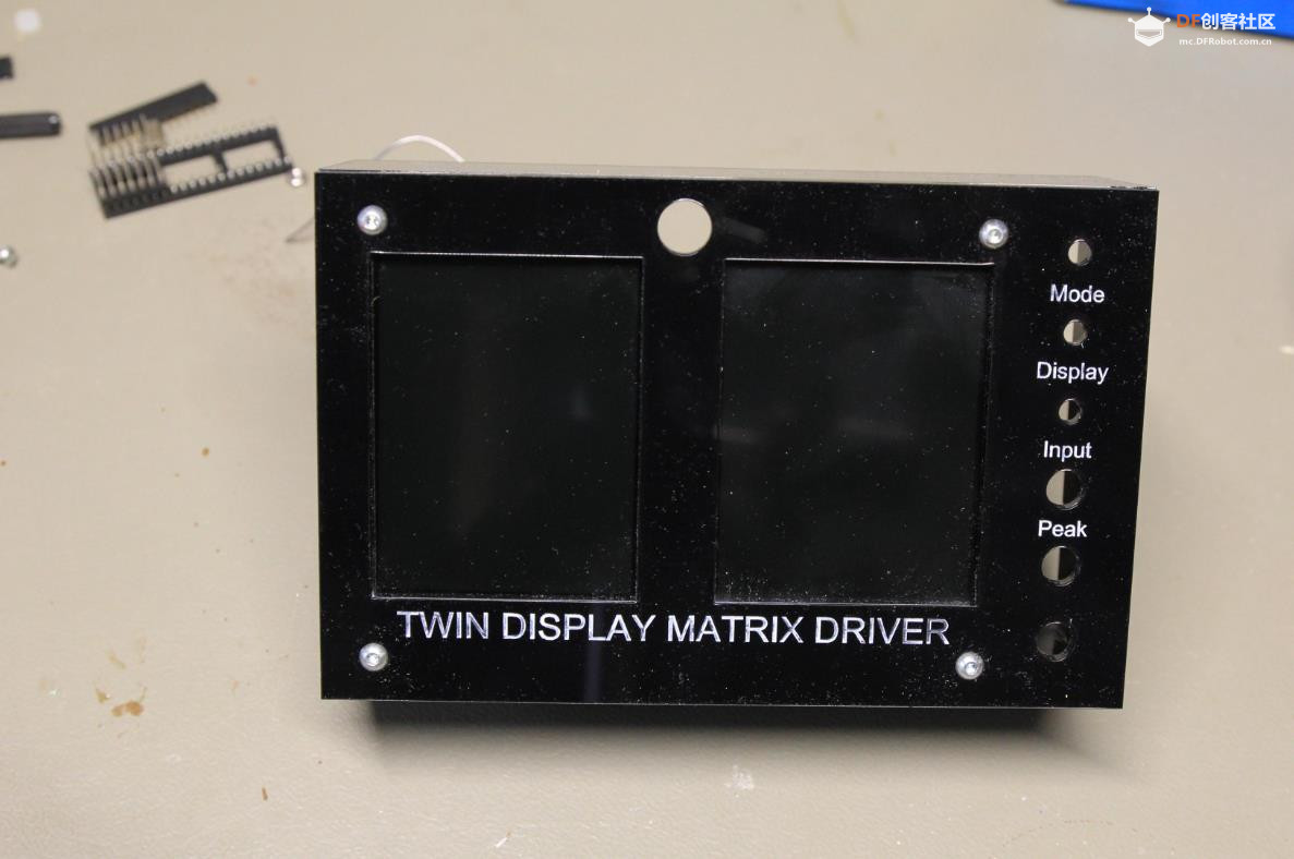
- #define BUTTON 2 // PIN0
- #define BUTTON2 3 // ADDED By MARK DONNERS
- //#define IR 4 // PIN4
- #define BUTTON3 4 // Pin xx Added By Mark Donners
-
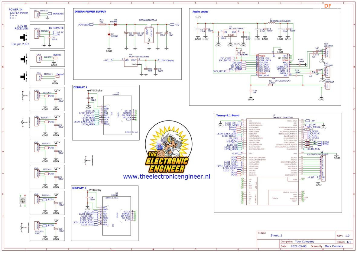
- // set the pins: here for SPI0 on Teensy 4.x
- // *** Recall that DC must be on a valid cs pin !!! ***
-
- // FIRST SCREEN IS WIRED TO SPI0
- #define PIN_SCK0 13 // mandatory
- #define PIN_MISO0 12 // mandatory
- #define PIN_MOSI0 11 // mandatory
- #define PIN_DC0 10 // mandatory
- #define PIN_CS0 9 // mandatory (but can be any digital pin)
- #define PIN_RESET0 6 // could be omitted (set to 255) yet it is better to use (any) digital pin whenever possible.
- #define PIN_BACKLIGHT0 5 // optional. Set this only if the screen LED pin is connected directly to the Teensy
- #define PIN_TOUCH_IRQ0 255 // optional. Set this only if touch is connected on the same spi bus (otherwise, set it to 255)
- #define PIN_TOUCH_CS0 255 // optional. Set this only if touch is connected on the same spi bus (otherwise, set it to 255)
-
- // ADDED By MARK DONNERS
- // SECOND SCREEN IS WIRED TO SPI1
- #define PIN_SCK1 27 // mandatory
- #define PIN_MISO1 1 // mandatory
- #define PIN_MOSI1 26 // mandatory
- #define PIN_DC1 0 // mandatory
- #define PIN_CS1 30 // mandatory (but can be any digital pin)
- #define PIN_RESET1 29 // could be omitted (set to 255) yet it is better to use (any) digital pin whenever possible.
- #define PIN_BACKLIGHT1 28 // optional. Set this only if the screen LED pin is connected directly to the Teensy
- #define PIN_TOUCH_IRQ1 255 // optional. Set this only if touch is connected on the same spi bus (otherwise, set it to 255)
- #define PIN_TOUCH_CS1 255 // optional. Set this only if touch is connected on the same spi bus (otherwise, set it to 255)
- // Changed the default SPI speed
- #define SPI_SPEED 50000000 // SPI speed
- #define SPI_SPEED2 50000000 // SPI speed
- //////////////////////////////////////////////////////////////////////////////////////////////////
- /**/
- #include <Wire.h>
- #include <Audio.h>
- #include "SPI.h"
- #include "ILI9341Driver.h"
- #include <ILI9341_T4.h>
- #include <tgx.h>
- #include <EEPROM.h>
- #include <OneButton.h>
- //IR#include <IRremote.h>
- #include <TeensyID.h>
- #include <Adafruit_NeoMatrix.h> // Fastled Neomatrix driver.
- #include <Adafruit_NeoPixel.h>
- #include "_timers.h"
- #include "globals.h"
- #include "Pixel_Spec.h"
- #include "helpers.h"
- #include "graphics.h"
- #include "_ili9341_t3n_font_Arial.h"
- #include "_ili9341_t3n_font_ArialBold.h"
-
- //////////////////////////////////////////////////////////////////////////////////////////////////
-
- /// <summary>
- /// inherit from the 'AudioControlSGTL5000' class to modify the CHIP_ANA_ADC_CTRL register
- /// </summary>
- #include "control_sgtl5000.h"
- class mSGTL5000 : public AudioControlSGTL5000 {
- public:
- void attGAIN(uint8_t att) {
- modify(0x0020, (att & 1) << 8, 1 << 8);
- }
- };
-
- // namespace for draw graphics primitives
- using namespace tgx;
-
- // Framebuffers and some variables below have moved to External memory, compared to orginal firmware
- // all related to the use of two displays
- // framebuffers
- DMAMEM uint16_t internalBuffer[240 * 320] = { 0 }; // used for internal buffering
- DMAMEM uint16_t internalBuffer1[240 * 320] = { 0 }; // used for internal buffering
- EXTMEM uint16_t frontBuffer[240 * 320] = { 0 }; // paint in this buffer
- EXTMEM uint16_t frontBuffer1[240 * 320] = { 0 }; // background buffer
- EXTMEM uint16_t backBuffer[240 * 320] = { 0 }; // background buffer
- EXTMEM uint16_t backBuffer1[240 * 320] = { 0 }; // background buffer
-
- /********************************************************************************************************************************
- * ** // Adafruit_NeoMaxtrix **
- ********************************************************************************************************************************/
- Adafruit_NeoMatrix matrix = Adafruit_NeoMatrix(kMatrixWidth, kMatrixHeight, LED_PIN,
- NEO_MATRIX_BOTTOM + NEO_MATRIX_RIGHT +
- NEO_MATRIX_COLUMNS + NEO_MATRIX_ZIGZAG,
- NEO_GRB + NEO_KHZ800);
-
- const uint16_t colors[] = {
- matrix.Color(255, 0, 0), matrix.Color(0, 255, 0), matrix.Color(0, 0, 255) };
-
-
- // samplebuffers
- int16_t samplesLeft[2048] = { 0 };
- int16_t samplesRight[2048] = { 0 };
-
- // screen driver objects
- ILI9341_T4::ILI9341Driver tft(PIN_CS0, PIN_DC0, PIN_SCK0, PIN_MOSI0, PIN_MISO0, PIN_RESET0, PIN_TOUCH_CS0, PIN_TOUCH_IRQ0); // for screen on SPI0
- ILI9341_T4::ILI9341Driver tft1(PIN_CS1, PIN_DC1, PIN_SCK1, PIN_MOSI1, PIN_MISO1, PIN_RESET1, PIN_TOUCH_CS1, PIN_TOUCH_IRQ1); // for screen on SPI1
-
- // two diff buffers
- ILI9341_T4::DiffBuffStatic<8000> diff1;
- ILI9341_T4::DiffBuffStatic<8000> diff2;
-
- // two diff buffers for second display
- ILI9341_T4::DiffBuffStatic<8000> diff3;
- ILI9341_T4::DiffBuffStatic<8000> diff4;
-
- // images that encapsulates framebuffers
- Image<RGB565> im(frontBuffer, 240, 320);
- Image<RGB565> im1(frontBuffer1, 240, 320);
- EXTMEM Image<RGB565> bg(backBuffer, 240, 320);
- EXTMEM Image<RGB565> bg1(backBuffer1, 240, 320);
-
- // instantiate button object
- OneButton btn(BUTTON, true, true);
- OneButton btn2(BUTTON2, true, true);
- OneButton btn3(BUTTON3, true, true);
- // GUItool: begin automatically generated code
- AudioInputI2S i2s1; //xy=205,270
- AudioOutputI2S i2s2; //xy=233.00000381469727,400.0000057220459
- AudioAnalyzeFFT1024 fft1024_1; //xy=425.00000762939453,132.00000190734863
- AudioAnalyzeFFT1024 fft1024_2; //xy=426.00000381469727,320.0000047683716
- AudioAnalyzeRMS rms1; //xy=431.00000381469727,93.00000190734863
- AudioRecordQueue queue2; //xy=431.00000381469727,280.00000381469727
- AudioAnalyzePeak peak1; //xy=432.00000762939453,54.000003814697266
- AudioRecordQueue queue1; //xy=432.00000381469727,171.00000381469727
- AudioMixer4 mixer1; //xy=432.00000381469727,225.00000381469727
- AudioAnalyzeRMS rms2; //xy=433.00000762939453,359.0000047683716
- AudioAnalyzePeak peak2; //xy=435.00000762939453,399.0000057220459
- AudioAnalyzeFFT1024 fft1024_3; //xy=566.0000076293945,225.00000286102295
- AudioConnection patchCord1(i2s1, 0, queue1, 0);
- AudioConnection patchCord2(i2s1, 0, peak1, 0);
- AudioConnection patchCord3(i2s1, 0, rms1, 0);
- AudioConnection patchCord4(i2s1, 0, fft1024_1, 0);
- AudioConnection patchCord5(i2s1, 0, mixer1, 0);
- AudioConnection patchCord6(i2s1, 0, i2s2, 0);
- AudioConnection patchCord7(i2s1, 1, queue2, 0);
- AudioConnection patchCord8(i2s1, 1, fft1024_2, 0);
- AudioConnection patchCord9(i2s1, 1, rms2, 0);
- AudioConnection patchCord10(i2s1, 1, peak2, 0);
- AudioConnection patchCord11(i2s1, 1, mixer1, 1);
- AudioConnection patchCord12(i2s1, 1, i2s2, 1);
- AudioConnection patchCord13(mixer1, fft1024_3);
- mSGTL5000 sgtl5000_1;
- // GUItool: end automatically generated code
-
- /// <summary>
- /// setup
- /// </summary>
- void setup() {
- Serial.println("enter setup");
- // The following code was added by Mark Donners to change the internal busspeed for the external Memory
- // turn on clock (TODO: increase clock speed later, slow & cautious for first release)
- CCM_CCGR7 |= CCM_CCGR7_FLEXSPI2(CCM_CCGR_OFF);
- CCM_CBCMR = (CCM_CBCMR & ~(CCM_CBCMR_FLEXSPI2_PODF_MASK | CCM_CBCMR_FLEXSPI2_CLK_SEL_MASK))
- | CCM_CBCMR_FLEXSPI2_PODF(4) | CCM_CBCMR_FLEXSPI2_CLK_SEL(2);
- CCM_CCGR7 |= CCM_CCGR7_FLEXSPI2(CCM_CCGR_ON);
-
- // link the button events
- btn.attachClick(buttonClick);
- btn.attachDoubleClick(buttonDoubleClick);
- btn.attachLongPressStart(buttonLongPressStart);
- btn.attachLongPressStop(buttonLongPressStop);
- btn.attachDuringLongPress(buttonLongPress);
-
- // Added functions for button2 by Mark Donners
- btn2.attachClick(button2Click);
- // added function for button 3 ( mode );
- btn3.attachClick(button3Click);
-
-
- // set bin ranges
- setBins();
-
- // Audio
- AudioMemory(128);//64
-
- sgtl5000_1.enable();
- InputSelect=!InputSelect; // we need to invert it once because it will change back in the button2Click function
- button2Click(); //this will call the subroutine where I change the input selector.
- // some default settings for the sgtl5000_1 where moved to the button2Click function
-
- // dsp
- sgtl5000_1.autoVolumeDisable();
- sgtl5000_1.surroundSoundDisable();
- sgtl5000_1.enhanceBassDisable();
-
- // fft
- fft1024_1.windowFunction(AudioWindowHanning1024);
- fft1024_2.windowFunction(AudioWindowHanning1024);
- fft1024_3.windowFunction(AudioWindowHanning1024);
-
- // display
- while (!tft.begin(SPI_SPEED)) delay(1000);
-
- tft.setScroll(0);
- tft.setFramebuffers(internalBuffer); // set 1 internal framebuffer -> activate float buffering
- tft.setDiffBuffers(&diff1, &diff2); // set the 2 diff buffers => activate differential updates
- tft.setDiffGap(16); // use a small gap for the diff buffers
- tft.setRefreshRate(120); // around 120hz for the display refresh rate
- tft.setVSyncSpacing(2); // set framerate = refreshrate/2 (and enable vsync at the same time)
-
- // ADDED by Mark Donners for Second Display
- while (!tft1.begin(SPI_SPEED2)) delay(1000);
- tft1.setScroll(0);
- tft1.setFramebuffers(internalBuffer1); // set 1 internal framebuffer -> activate float buffering
- tft1.setDiffBuffers(&diff3, &diff4); // set the 2 diff buffers => activate differential updates
- tft1.setDiffGap(16); // use a small gap for the diff buffers
- tft1.setRefreshRate(120); // around 120hz for the display refresh rate
- tft1.setVSyncSpacing(2); // set framerate = refreshrate/2 (and enable vsync at the same time)
-
- // make sure backlight is on
- if (PIN_BACKLIGHT0 != 255) {
- pinMode(PIN_BACKLIGHT0, OUTPUT);
- digitalWrite(PIN_BACKLIGHT0, HIGH);
- }
- // ADDED by Mark Donners for Second Display
- // make sure backlight is on
- if (PIN_BACKLIGHT1 != 255) {
- pinMode(PIN_BACKLIGHT1, OUTPUT);
- digitalWrite(PIN_BACKLIGHT1, HIGH);
- }
-
- // force reset to factory defaults
- if (digitalRead(BUTTON) == LOW) {
- clearEEPROM();
- // waiting for release the button
- while (digitalRead(BUTTON) == LOW) {}
- }
-
- // get config from EEPROM or initialize EEPROM
- if (isFirstStart()) {
- clearEEPROM();
- delay(3000);
- } else {
- readGLOBALConfig();
- readDBCorrection();
- readDIGITALConfig();
- readANALOGConfig();
- readFFTConfig();
- readGONIOConfig();
- readREMOTECONTROLConfig();
- }
-
- // show logo
- #if SHOWLOGO
- showLogo();
- #endif
-
- // initialize display from ModuleType
- initalizeDisplayFromModuleType(moduleType);
-
- matrix.begin();
- matrix.setTextColor(colors[0]);
-
- }
-
-
- int x = matrix.width();
- int pass = 0;
-
- /// <summary>
- /// mainloop
- /// </summary>
- void loop() {
- static elapsedMillis fps = 0;
- //oddeven=!oddeven;
- // watching the button
- btn.tick();
- // watching the button2
- btn2.tick();
- btn3.tick();
- // watching the serialport
-
- // draw modules
- if (!lockScreenUpdate && !DIGITAL_MenuActive && !ANALOG_MenuActive && !FFT_MenuActive && !GONIO_MenuActive) {
- drawAnalog2(false);
-
- if (moduleType == 0) drawDigital(false);
- else if (moduleType == 1) drawAnalog(false);
- else if (moduleType == 2) drawFFT(false);
- else if (moduleType == 3) drawGonio(false);
-
- // send global RMS & PPM data
- if (calibrate && fps > 16) {
- fps = 0;
- sendRMSPPM();
- }
- }
-
- ////*******************++
- //matrix.clear();
- int SENSE = analogRead(SENSEPOT)/2;
- Peakdelay= map(analogRead(PEAKDELAYPOT),0,1024,0,100); // this is the peak delay pot
-
- for(int i=0; i<numBands; i++) {
- FreqBinsNew[i]=(fft1024_3.read(Startbin,Stopbin) * SENSE);
- }
-
-
-
- // Process the data from bandValues and transform them into bar heights
- for (byte band = 0; band < numBands; band++)
- { // Scale the bars for the display
- int barHeight = FreqBinsNew[band];
- if (barHeight > TOP) barHeight = TOP;
- // Small amount of averaging between frames
- barHeight = ((FreqBinsOld[band] * 1) + barHeight) / 2; // Fast Filter, more rapid movement
- // barHeight = ((oldBarHeights[band] * 2) + barHeight) / 3; // minimum filter makes changes more smooth
-
- // Move peak up
-
- if (barHeight > peak[band])
- {
- peak[band] = min(TOP, barHeight);
- PeakFlag[band] = 1;
- }
-
- /*
- Mode 0: All leds OFF
- Mode 1: TriBar each Column is devided into 3 sections, Bottom,Middle and Top, Each section has different color
- Mode 2: Tribar without peaks
- Mode 3: No bars, only peaks in try color
- Mode 4: yellow bars white peaks
- Mode 5: yellow bars no peaks
- Mode 6: Center Bars yellow with red outerline
- Mode 7: Center Bars green with purple outerline
-
- */
-
-
-
- // Now visualize those bar heights
- switch (LedMode) {
- case 0:
- NoBars(band, barHeight);
- break;
-
- case 1:
- TriBar(band, barHeight);
- TriPeak(band);
- break;
-
-
- case 2:
- TriBar(band, barHeight);
- break;
-
- case 3:
- NoBars(band, barHeight);
- TriPeak(band);
- break;
-
-
- case 4:
- YellowBars(band, barHeight);
- NormalPeak(band,50,78,90);
- break;
-
- case 5:
- YellowBars(band, barHeight);
- break;
-
- case 6:
- centerBars(band, barHeight);
- break;
-
- case 7:
- centerBars2(band, barHeight);
- break;
-
- }
- FreqBinsOld[band] = barHeight; // Save oldBarHeights for averaging later
- }
-
-
- BRIGHTNEW=map(analogRead(BRIGHTPOT),0,1023,10,200);
-
- matrix.setBrightness(BRIGHTNEW);
- matrix.show();
-
-
- EVERY_N_MILLISECONDS(Fallingspeed) {
- for (byte band = 0; band < numBands; band++) {
- if (PeakFlag[band] == 1) {
- PeakTimer[band]++;
- if (PeakTimer[band] > Peakdelay) {
- PeakTimer[band] = 0;
- PeakFlag[band] = 0;
- }
- } else if (peak[band] > 0) {
- peak[band] -= 1;
- }
- }
-
- }
-
-
-
- }
-
- /// <summary>
- /// samples = sampleblocks * 128
- /// </summary>
- void setSampleBlocks() {
- lockScreenUpdate = true;
- queue1.freeBuffer();
- queue2.freeBuffer();
- memset(samplesLeft, 0, sizeof(samplesLeft));
- memset(samplesRight, 0, sizeof(samplesRight));
- GONIO_SampleBlocks = 8;
- if (GONIO_Samples == 1) GONIO_SampleBlocks = 16;
- lockScreenUpdate = false;
- }
-
- /// <summary>
- /// get samples for left and right channel
- /// </summary>
- /// <param name="blocks"></param>
- void getSamples(uint16_t blocks) {
- if (blocks == 0) {
- queue1.readBuffer();
- queue1.freeBuffer();
- queue2.readBuffer();
- queue2.freeBuffer();
- } else {
- if (queue1.available() >= blocks && queue2.available() >= blocks) {
- for (byte i = 0; i < blocks; i++) {
- memcpy(&samplesLeft[i * 128], queue1.readBuffer(), 256);
- memcpy(&samplesRight[i * 128], queue2.readBuffer(), 256);
- queue1.freeBuffer();
- queue2.freeBuffer();
- }
- }
- }
- }
-
- /// <summary>
- /// this function will be called when the button was pressed 1 time
- /// </summary>
- void buttonClick() {
- if (++moduleType > 3) moduleType = 0;
- modeSwitch();
- }
-
- /// this function will be called when the button2 was pressed 1 time
- /// ADDED By Mark Donners
- /// </summary>
- void button2Click() {
-
-
- if (InputSelect == AUDIO_INPUT_LINEIN) {
- // change parameters for optimal use with your mic
- InputSelect = AUDIO_INPUT_MIC;
- sgtl5000_1.inputSelect(InputSelect);
- sgtl5000_1.lineOutLevel(13); // 3.16 Volts p-p
- sgtl5000_1.volume(0.7f); // 0.8 corresponds to the maximum undistorted output for a full scale signal
- sgtl5000_1.lineInLevel(0); // 3.12 Volts p-p
- sgtl5000_1.attGAIN(0); // ADC volume range reduction down by 6.0 dB
- Serial.println("Input change to Microphone");
- }
-
- else {
- // change parameters for optimal use with your line in
- InputSelect = AUDIO_INPUT_LINEIN;
- sgtl5000_1.inputSelect(InputSelect);
- sgtl5000_1.lineOutLevel(13); // 3.16 Volts p-p
- sgtl5000_1.volume(0.7f); // 0.8 corresponds to the maximum undistorted output for a full scale signal
- sgtl5000_1.lineInLevel(0); // 3.12 Volts p-p
- sgtl5000_1.attGAIN(0); // ADC volume range reduction down by 6.0 dB
- Serial.println("Input change to Line-IN");
- }
-
-
- }
- void button3Click() {
- Serial.println("Mode button was pressed");
- LedMode++;
- if (LedMode>LedModeMax)LedMode=0;
- Serial.println(LedMode);
- }
- /// <summary>
- /// this function will be called when the button was pressed 2 times in a int16_t timeframe
- /// </summary>
- void buttonDoubleClick() {
- setSubMode(moduleType);
- }
-
- /// <summary>
- /// this function will be called often, while the button is pressed for a long time
- /// </summary>
- void buttonLongPress() {
- }
-
- /// <summary>
- /// this function will be called once, when the button is pressed for a long time
- /// </summary>
- void buttonLongPressStart() {
- calibrate = !calibrate;
- initalizeDisplayFromModuleType(moduleType);
- }
-
- /// <summary>
- /// this function will be called once, when the button is released after beeing pressed for a long time
- /// </summary>
- void buttonLongPressStop() {
- }
-
- /// <summary>
- /// switch module
- /// </summary>
- void modeSwitch() {
- lockScreenUpdate = true;
- EEPROM.put(20, moduleType);
- initalizeDisplayFromModuleType(moduleType);
- Serial.printf("{ModuleType=%i}", moduleType);
- lockScreenUpdate = false;
- }
-
- /// <summary>
- /// initialize display from ModuleType
- /// </summary>
- /// <param name="mType"></param>
- void initalizeDisplayFromModuleType(int16_t mType) {
- if (mType < 0 || mType > 3) {
- mType = 0;
- moduleType = 0;
- }
-
- lockScreenUpdate = true;
- if (mType == 0) displayInitDigital(true);
- if (mType == 1) displayInitAnalog();
- if (mType == 2) displayInitFFT(true);
- if (mType == 3) displayInitGonio(true);
- display2InitAnalog(); // second display always vu meter
-
- lockScreenUpdate = false;
-
-
- }
-
- /// <summary>
- /// set subMode
- /// </summary>
- void setSubMode(int16_t mType) {
- lockScreenUpdate = true;
- switch (mType) {
- case 0: // digitalmeter
- if (++DIGITAL_WorkMode > 3) DIGITAL_WorkMode = 0;
- EEPROM.put(504, DIGITAL_WorkMode);
- setMode(true);
- break;
- case 1:
- break;
- case 2: // spectrumanalyzer
- if (++FFT_WorkMode > 11) FFT_WorkMode = 0;
- EEPROM.put(706, FFT_WorkMode);
- setMode(true);
- break;
- case 3: // goniometer
- if (++GONIO_WorkMode > 7) GONIO_WorkMode = 0;
- EEPROM.put(806, GONIO_WorkMode);
- setMode(true);
- break;
- }
- lockScreenUpdate = false;
- }
-
- /// <summary>
- /// set mode
- /// </summary>
- void setMode(bool showMessage) {
- switch (moduleType) {
- case 0: // digitalmeter
- switch (DIGITAL_WorkMode) {
- case 0:
- DIGITAL_dBLow = -40;
- DIGITAL_PeakHold = false;
- if (showMessage) messageBox("-40dB");
- break;
- case 1:
- DIGITAL_dBLow = -30;
- DIGITAL_PeakHold = false;
- if (showMessage) messageBox("-30dB");
- break;
- case 2:
- DIGITAL_dBLow = -40;
- DIGITAL_PeakHold = true;
- if (showMessage) messageBox("-40dB HOLD");
- break;
- case 3:
- DIGITAL_dBLow = -30;
- DIGITAL_PeakHold = true;
- if (showMessage) messageBox("-30dB HOLD");
- break;
- }
- break;
-
- case 1: // analogmeter
- break;
-
- case 2: // spectrumanalyzer
- switch (FFT_WorkMode) {
- case 0:
- FFT_dBLow = -40;
- FFT_LevelBarMode = 1 /*RMS*/;
- FFT_PeakHold = false;
- if (showMessage) messageBox("RMS -40dB");
- break;
- case 1:
- FFT_dBLow = -40;
- FFT_LevelBarMode = 0 /*PEAK*/;
- FFT_PeakHold = false;
- if (showMessage) messageBox("PPM -40dB");
- break;
- /*****************************************/
- case 2:
- FFT_dBLow = -30;
- FFT_LevelBarMode = 1 /*RMS*/;
- FFT_PeakHold = false;
- if (showMessage) messageBox("RMS -30dB");
- break;
- case 3:
- FFT_dBLow = -30;
- FFT_LevelBarMode = 0 /*PEAK*/;
- FFT_PeakHold = false;
- if (showMessage) messageBox("PPM -30dB");
- break;
- /*****************************************/
- case 4:
- FFT_dBLow = -40;
- FFT_LevelBarMode = 1 /*RMS*/;
- FFT_PeakHold = true;
- if (showMessage) messageBox("RMS.HOLD -40dB");
- break;
- case 5:
- FFT_dBLow = -40;
- FFT_LevelBarMode = 0 /*PEAK*/;
- FFT_PeakHold = true;
- if (showMessage) messageBox("P.HOLD -40dB");
- break;
- /*****************************************/
- case 6:
- FFT_dBLow = -30;
- FFT_LevelBarMode = 1 /*RMS*/;
- FFT_PeakHold = true;
- if (showMessage) messageBox("RMS.HOLD -30dB");
- break;
- case 7:
- FFT_dBLow = -30;
- FFT_LevelBarMode = 0 /*PEAK*/;
- FFT_PeakHold = true;
- if (showMessage) messageBox("P.HOLD -30dB");
- break;
- /*****************************************/
- case 8:
- FFT_dBLow = -40;
- FFT_LevelBarMode = 1 /*RMS*/;
- FFT_PeakHold = true;
- if (showMessage) messageBox("RMS.HOLD4 -40dB");
- break;
- case 9:
- FFT_dBLow = -40;
- FFT_LevelBarMode = 0 /*PEAK*/;
- FFT_PeakHold = true;
- if (showMessage) messageBox("P.HOLD4 -40dB");
- break;
- /*****************************************/
- case 10:
- FFT_dBLow = -30;
- FFT_LevelBarMode = 1 /*RMS*/;
- FFT_PeakHold = true;
- if (showMessage) messageBox("RMS.HOLD4 -30dB");
- break;
- case 11:
- FFT_dBLow = -30;
- FFT_LevelBarMode = 0 /*PEAK*/;
- FFT_PeakHold = true;
- if (showMessage) messageBox("P.HOLD4 -30dB");
- break;
- }
- break;
-
- case 3: // goniometer
- switch (GONIO_WorkMode) {
- case 0:
- GONIO_dBLow = -40;
- GONIO_BarMode = 1 /*RMS*/;
- GONIO_PeakHold = false;
- if (showMessage) messageBox("RMS -40dB");
- break;
- case 1:
- GONIO_dBLow = -40;
- GONIO_BarMode = 0 /*PEAK*/;
- GONIO_PeakHold = false;
- if (showMessage) messageBox("PPM -40dB");
- break;
- case 2:
- GONIO_dBLow = -30;
- GONIO_BarMode = 1 /*RMS*/;
- GONIO_PeakHold = false;
- if (showMessage) messageBox("RMS -30dB");
- break;
- case 3:
- GONIO_dBLow = -30;
- GONIO_BarMode = 0 /*PEAK*/;
- GONIO_PeakHold = false;
- if (showMessage) messageBox("PPM -30dB");
- break;
- case 4:
- GONIO_dBLow = -40;
- GONIO_BarMode = 1 /*RMS*/;
- GONIO_PeakHold = true;
- if (showMessage) messageBox("RMS.HOLD -40dB");
- break;
- case 5:
- GONIO_dBLow = -40;
- GONIO_BarMode = 0 /*PEAK*/;
- GONIO_PeakHold = true;
- if (showMessage) messageBox("P.HOLD -40dB");
- break;
- case 6:
- GONIO_dBLow = -30;
- GONIO_BarMode = 1 /*RMS*/;
- GONIO_PeakHold = true;
- if (showMessage) messageBox("RMS.HOLD -30dB");
- break;
- case 7:
- GONIO_dBLow = -30;
- GONIO_BarMode = 0 /*PEAK*/;
- GONIO_PeakHold = true;
- if (showMessage) messageBox("P.HOLD -30dB");
- break;
- }
- break;
- }
- }
-
- /// <summary>
- /// start queue
- /// </summary>
- void queueStart() {
- queue1.clear();
- queue2.clear();
- queue1.begin();
- queue2.begin();
- }
-
- /// <summary>
- /// stop queue
- /// </summary>
- void queueStop() {
- queue1.end();
- queue2.end();
- queue1.clear();
- queue2.clear();
- queue1.freeBuffer();
- queue2.freeBuffer();
- }
-
- void TriBar(int band, int barHeight) {
- int x = band;
- // first draw active pixels
- for (int y = TOP; y >= TOP - barHeight; y--) {
- if (y < 4) matrix.drawPixel(x, y, matrix.Color(70,0,0)); //Top red
- else if (y > 8) matrix.drawPixel(x, y, matrix.Color(0,70,0)); //red
- else matrix.drawPixel(x, y, matrix.Color(0,0,70));
- }
- // now draw empty pixels
- for ( int y2=TOP;y2>barHeight;y2--){
- matrix.drawPixel(x, 16-y2, matrix.Color(0,0,0));
- }
-
-
- }
- void TriPeak(int band) {
- int xStart = band;
- int peakHeight = TOP - peak[band] - 1;
- for (int x = xStart; x < xStart + 1; x++) {
- if (peakHeight < 4) matrix.drawPixel(x, peakHeight, matrix.Color(70,0,0)); //Top red
- else if (peakHeight > 8) matrix.drawPixel(x, peakHeight, matrix.Color(0,70,0)); //green
- else matrix.drawPixel(x, peakHeight, matrix.Color(0,0,70));
- }
- }
-
- void NormalPeak(int band, int R, int G, int B) {
- int xStart = band;
- int peakHeight = TOP - peak[band] - 1;
- for (int x = xStart; x < xStart + 1; x++) {
- matrix.drawPixel(x, peakHeight, matrix.Color(R,G,B));
- }
- }
-
-
- void YellowBars(int band, int barHeight) {
- int x = band;
- // first draw active pixels
- for (int y = TOP; y >= TOP - barHeight; y--) {
- matrix.drawPixel(x, y, matrix.Color(70,70,0));
- }
- // now draw empty pixels
- for ( int y2=TOP;y2>barHeight;y2--){
- matrix.drawPixel(x, kMatrixHeight-y2, matrix.Color(0,0,0));
- }
- }
-
- void NoBars(int band, int barHeight) {
- int x = band;
- // first draw active pixels
- for (int y = TOP; y >= TOP - barHeight; y--) {
- matrix.drawPixel(x, y, matrix.Color(0,0,0));
- }
- // now draw empty pixels
- for ( int y2=TOP;y2>barHeight;y2--){
- matrix.drawPixel(x, kMatrixHeight-y2, matrix.Color(0,0,0));
- }
- }
-
-
-
-
- void centerBars(int band, int barHeight) {
- int x = band;
- barHeight=(barHeight/2)+(kMatrixHeight/2);
- for (int y=(kMatrixHeight/2);y<kMatrixHeight;y++){
- if (y<=barHeight){
- if(y==barHeight){
- matrix.drawPixel(x, y, matrix.Color(70,0,0));
- matrix.drawPixel(x, (15-y), matrix.Color(70,0,0));
- }
- else{
- matrix.drawPixel(x, y, matrix.Color(70,30,10));
- matrix.drawPixel(x, (15-y), matrix.Color(70,30,10));
- }
- }
- if (y>barHeight){
- matrix.drawPixel(x, y, matrix.Color(0,0,0));
- matrix.drawPixel(x, 15-y, matrix.Color(0,0,0));
- }
-
- }
-
- }
-
- void centerBars2(int band, int barHeight) {
- int x = band;
- barHeight=(barHeight/2)+(kMatrixHeight/2);
- for (int y=(kMatrixHeight/2);y<kMatrixHeight;y++){
- if (y<=barHeight){
- if(y==barHeight){
- matrix.drawPixel(x, y, matrix.Color(70,0,70));
- matrix.drawPixel(x, (15-y), matrix.Color(70,0,70));
- }
- else{
- matrix.drawPixel(x, y, matrix.Color(0,70,10));
- matrix.drawPixel(x, (15-y), matrix.Color(0,70,10));
- }
- }
- if (y>barHeight){
- matrix.drawPixel(x, y, matrix.Color(0,0,0));
- matrix.drawPixel(x, 15-y, matrix.Color(0,0,0));
- }
-
- }
-
- }
|


 沪公网安备31011502402448
 置顶卡
置顶卡 变色卡
变色卡 千斤顶
千斤顶
 萌萌哒新人
萌萌哒新人
 活跃会员
活跃会员
 宣传大使
宣传大使
 牛X认证
牛X认证
 创作达人
创作达人
 ARD DAY
 摸鱼团员
摸鱼团员
 志“童”道合
 编辑选择奖
编辑选择奖


