本帖最后由 御坂10032号 于 2025-10-15 22:48 编辑
简介
本文的主要内容是如何使用ESP-IDF的I2C驱动来驱动BH1750光照传感器从而实现光照强度Lux的读取。
正文
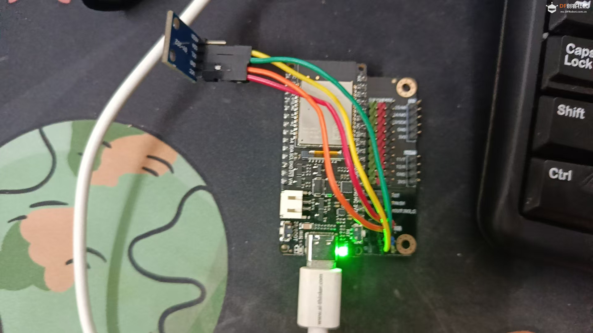
在文章开始之前,我要首先夸赞一下DF的这个底板设计,这里额外引出的I2C的pin设计的很好,三个引脚,还自带VCC和GND。可以解决非使用QWI2C线缆同时接多个I2C设备PIN不够用的情况(或者使用面包板转接,相信设计的时候也考虑到了这个问题)
LED运行状态指示
在上一篇文章中我们已经实现了LED的Toggle,我发现如果这个LED作为一个运行状态的指示非常好,于是在这次的代码中就进行了保留。
下面为LED配置的代码
- static void configure_led(void)
- {
- ESP_LOGI(TAG, "Configuring GPIO15 as output with pull-up!");
-
- /* Reset the GPIO pin */
- gpio_reset_pin(BLINK_GPIO);
-
- /* Configure GPIO as output with pull-up */
- gpio_config_t io_conf = {
- .intr_type = GPIO_INTR_DISABLE,
- .mode = GPIO_MODE_OUTPUT,
- .pin_bit_mask = (1ULL << BLINK_GPIO),
- .pull_down_en = GPIO_PULLDOWN_DISABLE,
- .pull_up_en = GPIO_PULLUP_ENABLE,
- };
- gpio_config(&io_conf);
-
- /* Set initial state to LOW */
- gpio_set_level(BLINK_GPIO, 0);
- }
下面为LED闪烁的控制代码
- static void blink_led_task(void *pvParameter)
- {
- /* Toggle the GPIO level */
- while (1)
- {
- ESP_LOGI(TAG, "Turning the LED %s!", s_led_state ? "ON" : "OFF");
- s_led_state = !s_led_state;
- gpio_set_level(BLINK_GPIO, s_led_state);
- vTaskDelay(pdMS_TO_TICKS(1000)); // 1 second delay
- }
-
- /* Task should never reach here, but if it does, delete itself */
- vTaskDelete(NULL);
- }
然后在main方法中启动这个任务就好
- xTaskCreate(blink_led_task, "blink_led", 2048, NULL, 5, &led_task_handle);
BH1750光照传感器驱动
首先我们需要根据硬件和对应的底板等来定义对应的I2C pin 和时钟(一般100K-400K都可以)
- #define I2C_MASTER_SCL_IO 10 // SCL时钟线连接到GPIO 10
- #define I2C_MASTER_SDA_IO 9 // SDA数据线连接到GPIO 9
- #define I2C_MASTER_NUM I2C_NUM_0 // 使用I2C端口0
- #define I2C_MASTER_FREQ_HZ 100000 // I2C时钟频率100kHz(标准模式)
- #define I2C_MASTER_TIMEOUT_MS 1000 // I2C操作超时时间1秒
之后根据上面定义的I2C信息来初始化I2C- static esp_err_t i2c_master_init(void)
- {
- int i2c_master_port = I2C_MASTER_NUM;
-
- i2c_config_t conf = {
- .mode = I2C_MODE_MASTER,
- .sda_io_num = I2C_MASTER_SDA_IO,
- .scl_io_num = I2C_MASTER_SCL_IO,
- .sda_pullup_en = GPIO_PULLUP_ENABLE,
- .scl_pullup_en = GPIO_PULLUP_ENABLE,
- .master.clk_speed = I2C_MASTER_FREQ_HZ,
- };
-
- i2c_param_config(i2c_master_port, &conf);
-
- return i2c_driver_install(i2c_master_port, conf.mode, I2C_MASTER_RX_BUF_DISABLE, I2C_MASTER_TX_BUF_DISABLE, 0);
- }
需要注意的一点是这里我们初始化I2C之后初始的I2C是0,那么之后我们就可以通过I2C 0 来操作对应在这个总线上的设备了。
之后我们使用I2C Scan函数来帮助我们确定挂载在总线上的I2C设备。
- /**
- * @brief I2C scanner function
- */
- static void i2c_scanner(void)
- {
- ESP_LOGI(TAG, "Starting I2C scan...");
-
- uint8_t address;
- esp_err_t ret;
- int devices_found = 0;
-
- for (address = 1; address < 127; address++)
- {
- i2c_cmd_handle_t cmd = i2c_cmd_link_create();
- i2c_master_start(cmd);
- i2c_master_write_byte(cmd, (address << 1) | I2C_MASTER_WRITE, true);
- i2c_master_stop(cmd);
-
- ret = i2c_master_cmd_begin(I2C_MASTER_NUM, cmd, 10 / portTICK_PERIOD_MS);
- i2c_cmd_link_delete(cmd);
-
- if (ret == ESP_OK)
- {
- ESP_LOGI(TAG, "Found device at address: 0x%02X", address);
- devices_found++;
- }
- }
-
- if (devices_found == 0)
- {
- ESP_LOGI(TAG, "No I2C devices found!");
- }
- else
- {
- ESP_LOGI(TAG, "Scan completed. Found %d device(s).", devices_found);
- }
- }
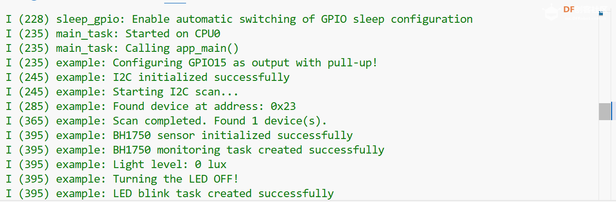
如下图,正确的扫描的I2C的设备0x23, 对应其BH1750传感器
之后我们定义BH1750的寄存器信息,稍后会用到。
- #define BH1750_POWER_DOWN 0x00 // 断电指令
- #define BH1750_POWER_ON 0x01 // 上电指令
- #define BH1750_RESET 0x07 // 重置数据寄存器
- #define BH1750_CONT_HIGH_RES 0x10 // 连续高分辨率测量(1lx,120ms)
然后我们使用命令链的方式封装一个读和写的操作。
- /**
- * @brief 向BH1750发送指令
- */
- static esp_err_t bh1750_write_cmd(uint8_t cmd)
- {
- i2c_cmd_handle_t i2c_cmd = i2c_cmd_link_create();
- i2c_master_start(i2c_cmd);
- i2c_master_write_byte(i2c_cmd, (bh1750_addr << 1) | I2C_MASTER_WRITE, true);
- i2c_master_write_byte(i2c_cmd, cmd, true);
- i2c_master_stop(i2c_cmd);
-
- esp_err_t ret = i2c_master_cmd_begin(I2C_MASTER_NUM, i2c_cmd, I2C_MASTER_TIMEOUT_MS / portTICK_PERIOD_MS);
- i2c_cmd_link_delete(i2c_cmd);
-
- return ret;
- }
-
- /**
- * @brief 从BH1750读取数据
- */
- static esp_err_t bh1750_read_data(uint8_t *data, size_t len)
- {
- i2c_cmd_handle_t i2c_cmd = i2c_cmd_link_create();
- i2c_master_start(i2c_cmd);
- i2c_master_write_byte(i2c_cmd, (bh1750_addr << 1) | I2C_MASTER_READ, true);
-
- if (len > 1)
- {
- i2c_master_read(i2c_cmd, data, len - 1, I2C_MASTER_ACK);
- }
- i2c_master_read_byte(i2c_cmd, data + len - 1, I2C_MASTER_NACK);
- i2c_master_stop(i2c_cmd);
-
- esp_err_t ret = i2c_master_cmd_begin(I2C_MASTER_NUM, i2c_cmd, I2C_MASTER_TIMEOUT_MS / portTICK_PERIOD_MS);
- i2c_cmd_link_delete(i2c_cmd);
-
- return ret;
- }
相信大家看出来了,上述的I2C操作相对于传统的方式有所不同,相对传统方式I2C 命令链是一种将多步 I2C 操作(如 START、WRITE、READ、STOP)打包成一条指令序列并一次性执行的机制,相比传统逐步读写方式,它能显著简化代码、减少 CPU 干预、提高通信效率和可靠性,是 ESP-IDF 推荐的 I2C 操作方式。
之后我们便可以来初始化传感器。
- /**
- * @brief Initialize BH1750 sensor
- */
- static esp_err_t bh1750_init_sensor(void)
- {
- esp_err_t ret;
-
- // 先断电再上电,复位传感器
- ret = bh1750_write_cmd(BH1750_POWER_DOWN);
- if (ret != ESP_OK)
- {
- ESP_LOGE(TAG, "Failed to power down BH1750: %s", esp_err_to_name(ret));
- return ret;
- }
-
- vTaskDelay(pdMS_TO_TICKS(10)); // 等待10ms
-
- // 上电
- ret = bh1750_write_cmd(BH1750_POWER_ON);
- if (ret != ESP_OK)
- {
- ESP_LOGE(TAG, "Failed to power on BH1750: %s", esp_err_to_name(ret));
- return ret;
- }
-
- vTaskDelay(pdMS_TO_TICKS(10)); // 等待10ms
-
- // 重置数据寄存器
- ret = bh1750_write_cmd(BH1750_RESET);
- if (ret != ESP_OK)
- {
- ESP_LOGE(TAG, "Failed to reset BH1750: %s", esp_err_to_name(ret));
- return ret;
- }
-
- vTaskDelay(pdMS_TO_TICKS(10)); // 等待10ms
-
- // 设置为连续高分辨率模式
- ret = bh1750_write_cmd(BH1750_CONT_HIGH_RES);
- if (ret != ESP_OK)
- {
- ESP_LOGE(TAG, "Failed to set BH1750 mode: %s", esp_err_to_name(ret));
- return ret;
- }
-
- ESP_LOGI(TAG, "BH1750 sensor initialized successfully");
- return ESP_OK;
- }
然后来根据数据手册计算LUX的方法。
- /**
- * @brief Read light level from BH1750 sensor
- */
- static esp_err_t bh1750_read_light(uint16_t *lux)
- {
- uint8_t data[2];
- esp_err_t ret = bh1750_read_data(data, 2);
-
- if (ret != ESP_OK)
- {
- ESP_LOGE(TAG, "Failed to read from BH1750: %s", esp_err_to_name(ret));
- return ret;
- }
-
- // BH1750返回的是16位大端序数据
- // 高字节在前,低字节在后
- uint16_t raw_data = (data[0] << 8) | data[1];
-
- // 在高分辨率模式下,每个计数值等于1.2lux
- // 转换公式: lux = raw_data / 1.2
- // 为了避免浮点运算,使用整数运算: lux = raw_data * 10 / 12
- *lux = (raw_data * 10) / 12;
-
- return ESP_OK;
- }
然后撰写读取BH1750 LUX的方法,实际上就是调用上述方法,两秒一次。
-
- /**
- * @brief BH1750 monitoring task
- */
- static void bh1750_task(void *pvParameter)
- {
- uint16_t lux;
-
- while (1)
- {
- if (bh1750_read_light(&lux) == ESP_OK)
- {
- ESP_LOGI(TAG, "Light level: %d lux", lux);
- }
-
- vTaskDelay(pdMS_TO_TICKS(2000)); // Read every 2 seconds
- }
-
- vTaskDelete(NULL);
- }
完整的Main方法
- void app_main(void)
- {
- configure_led();
-
- // Initialize I2C master
- ESP_ERROR_CHECK(i2c_master_init());
- ESP_LOGI(TAG, "I2C initialized successfully");
-
- // Perform I2C scan
- i2c_scanner();
-
- // Initialize BH1750 sensor
- esp_err_t ret = bh1750_init_sensor();
- if (ret == ESP_OK)
- {
- // Create BH1750 monitoring task
- xTaskCreate(bh1750_task, "bh1750_task", 4096, NULL, 4, NULL);
- ESP_LOGI(TAG, "BH1750 monitoring task created successfully");
- }
- else
- {
- ESP_LOGE(TAG, "Failed to initialize BH1750 sensor, skipping light monitoring");
- }
-
- xTaskCreate(blink_led_task, "blink_led", 2048, NULL, 5, &led_task_handle);
-
- ESP_LOGI(TAG, "LED blink task created successfully");
- }
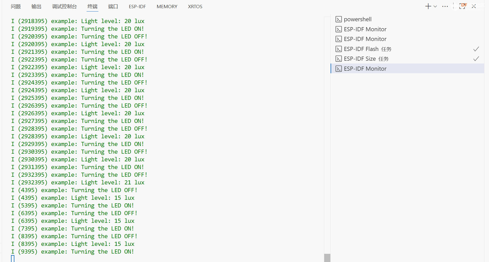
实验现象如下:
总结
原本是打算直接用组件管理器中的BH1750驱动进行驱动的,但是没有研究明白,一直通信失败。最后还是决定自己写一次驱动好了。这样可以直接的了解I2C的命令链模式和BH1750的驱动开发。
 blink-led.zip blink-led.zip
| 


 沪公网安备31011502402448
 置顶卡
置顶卡 变色卡
变色卡 千斤顶
千斤顶


