本帖最后由 驴友花雕 于 2025-6-6 17:49 编辑
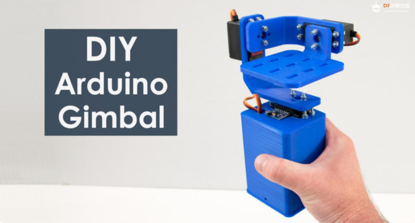
在本教程中,我们将学习如何构建 Arduino Gimbal 或使用伺服电机的自稳定平台。本教程实际上是上一个关于 MPU6050 教程的教程的扩展。
目录
1、概述
DIY Arduino Gimbal - 自稳平台 STL 文件
2、装配
3、Arduino Gimbal 电路图
Arduino 代码
4、DIY Arduino Gimbal - 自稳定平台 Code
一、概述
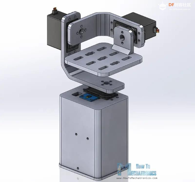
我使用 3D 建模软件设计了万向节。它由 3 个用于 3 轴控制的 MG996R 伺服电机和一个放置MPU6050传感器、Arduino 和电池的底座组成。
Arduino Gimbal 3D 模型
您可以在 Thangs 上找到并下载此 3D 模型,并在浏览器中进行探索。
DIY Arduino Gimbal - 自稳平台 STL 文件(见项目下载)
使用我的 Creality CR-10 3D 打印机,我 3D 打印了所有部件,它们都非常完美。
DIY Gimbal 3D 打印部件
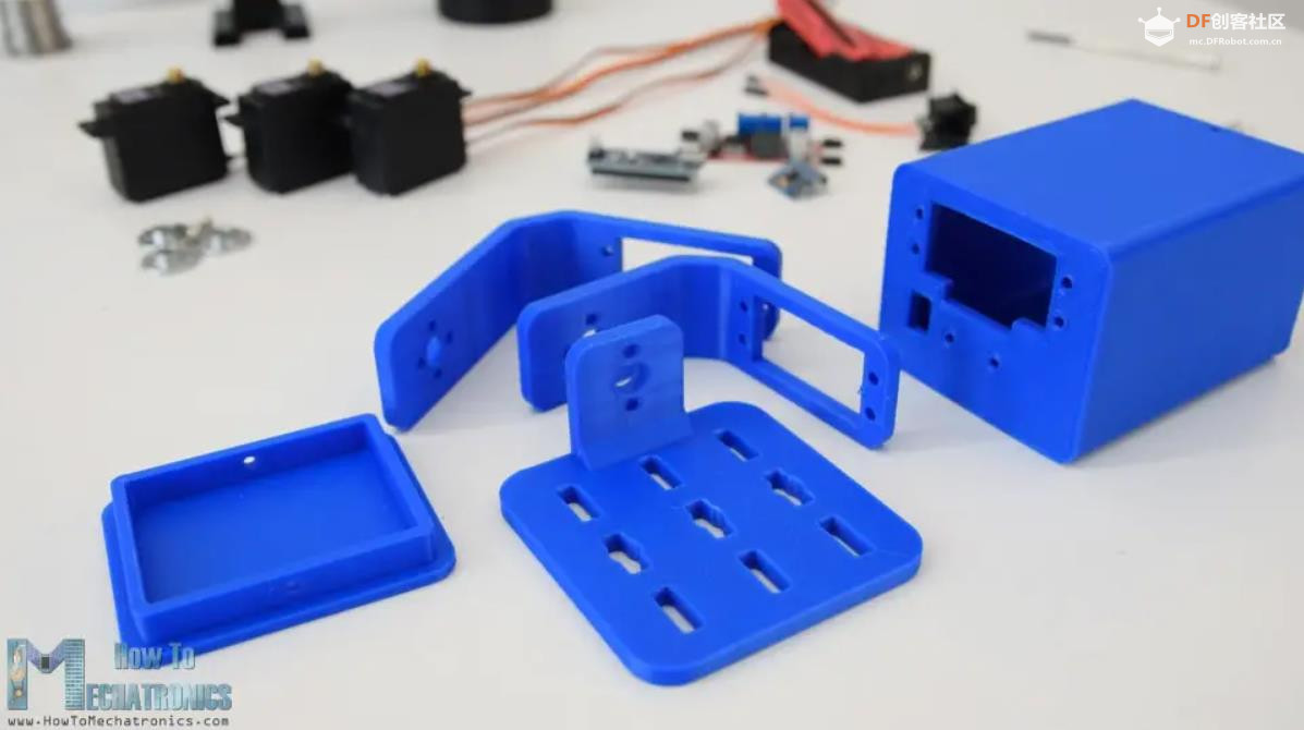
二、装配
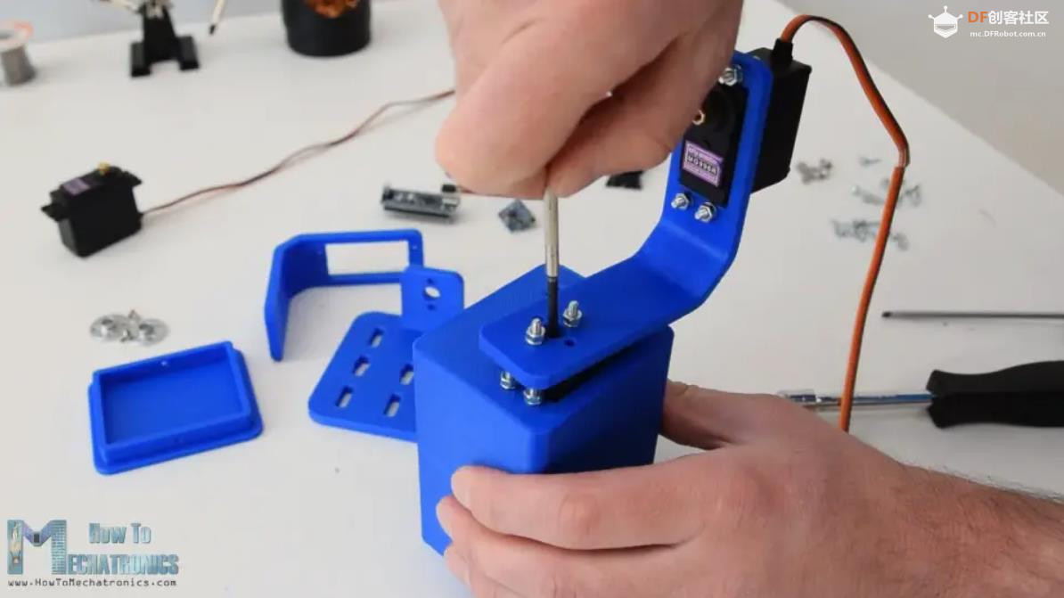
组装万向节非常简单。我从安装 Yaw 伺服开始。我使用 M3 螺栓和螺母将其固定到底座上。
Arduino 云台伺服电机安装
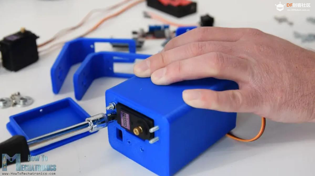
接下来,使用相同的方法固定 Roll 伺服器。这些部件经过专门设计,可轻松安装 MG996R 伺服系统。
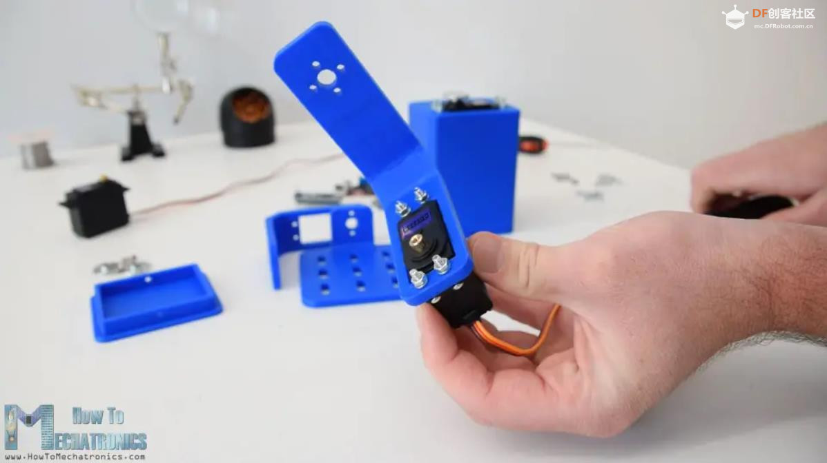
为了将零件相互连接,我使用了圆角,它是伺服器的附件。
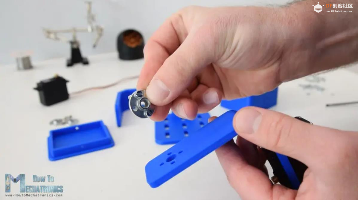
首先,我们需要用两个螺栓将圆角固定到底座上,然后用另一个螺栓将其连接到前一个伺服器上。
组装 Arduino 云台
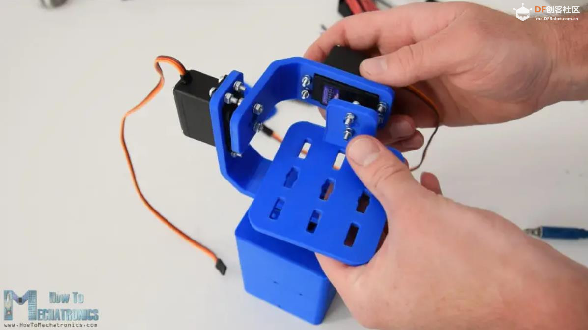
我重复了这个过程来组装其余的组件,即 Pitch 伺服器和顶部平台。
Arduino 自稳定平台
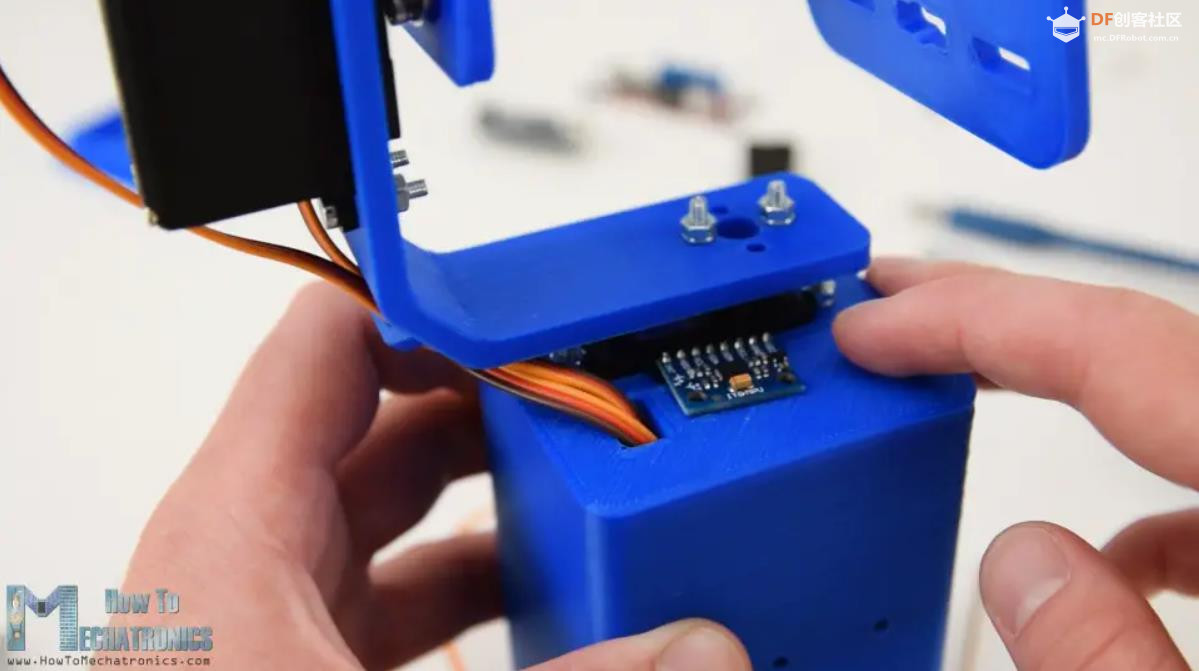
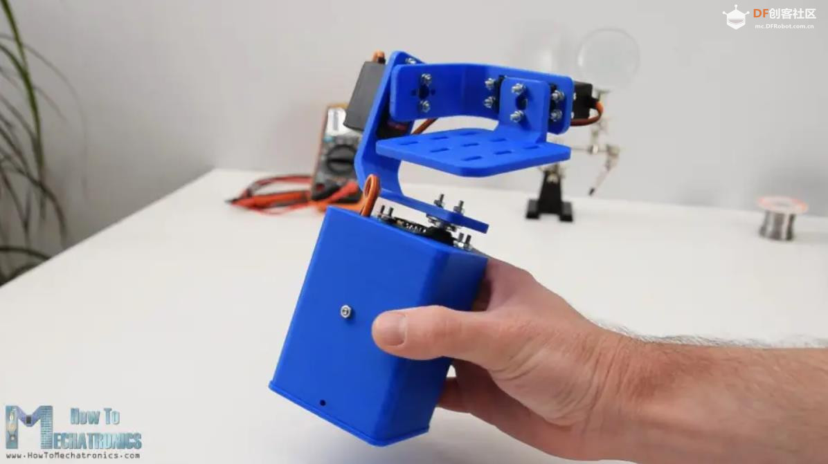
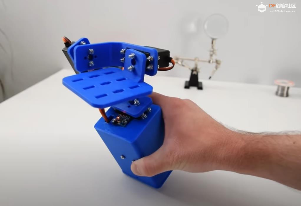
接下来,我将伺服线穿过支架开口,以保持它们井井有条。然后我插入 MPU6050 传感器并用螺栓和螺母将其固定在底座上。
带有 MPU6050 传感器的 Arduino 自稳定平台
为了给项目供电,我使用了 2 节锂离子电池,并将其放在这个电池座中。我使用两个螺栓和螺母将电池座固定到底座上。
锂离子电池座
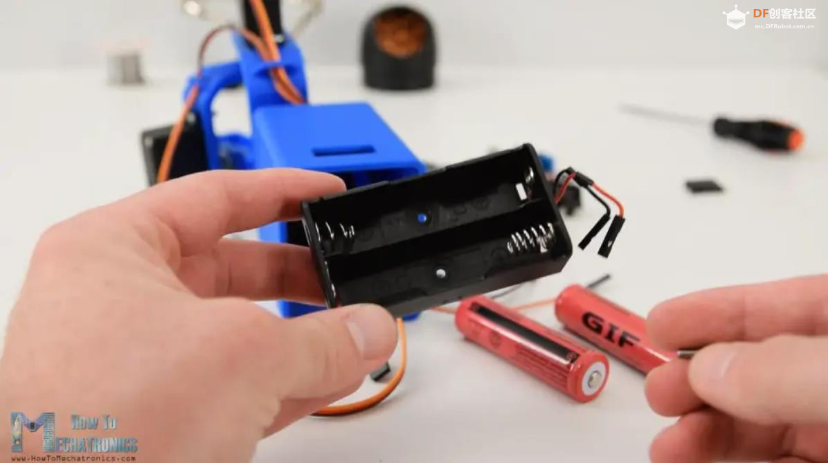
2 节锂离子电池将产生大约 7.4V 的电压,但我们需要 5V 来为 Arduino 和伺服系统供电。
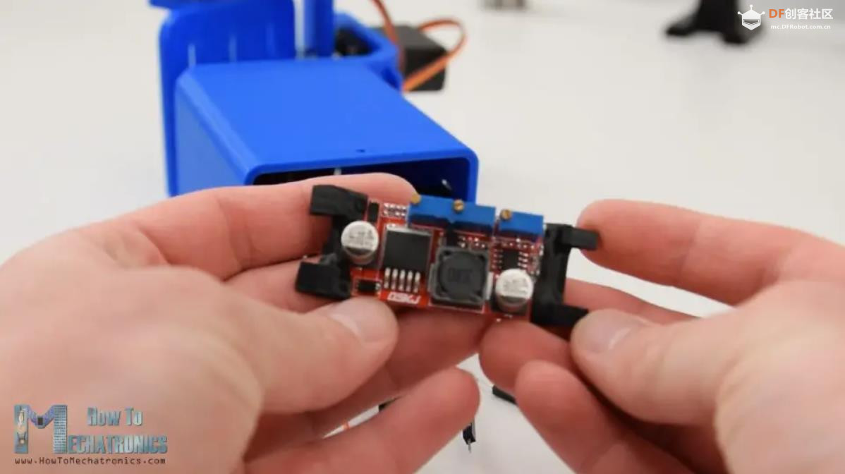
这就是为什么我使用了一个降压转换器,它可以将 7.4V 转换为 5V。
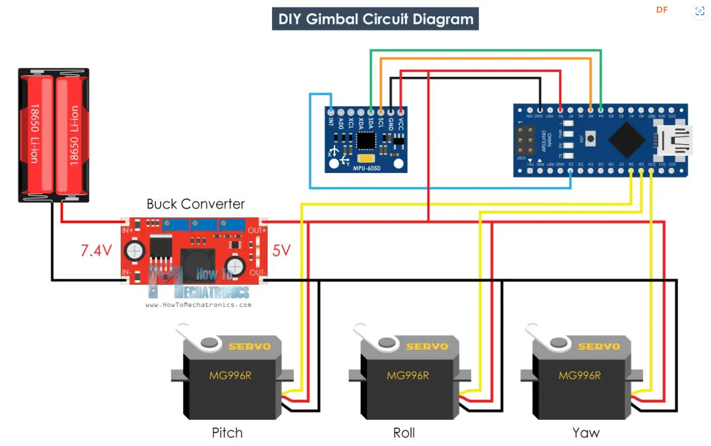
三、Arduino Gimbal 电路图
现在剩下的就是把所有东西都连接在一起。这是这个项目的电路图以及需要如何连接所有内容。
DIY Arduino Gimbal - 自稳定平台
您可以自行获取此 Arduino 教程所需的组件:
MPU6050 IMU .....................................亚马逊 / Banggood / 全球速卖通
MG996R 伺服.....................................亚马逊 / Banggood / 全球速卖通
Buck Converter .................................... 降压转换器亚马逊 / Banggood / 全球速卖通
Arduino 板 .....................................亚马逊 / Banggood / 全球速卖通
试验板和跳线 ............亚马逊 / Banggood / 全球速卖通
最后,我将电子元件和电线挤入底座中,并使用底部的这个盖子覆盖它们。
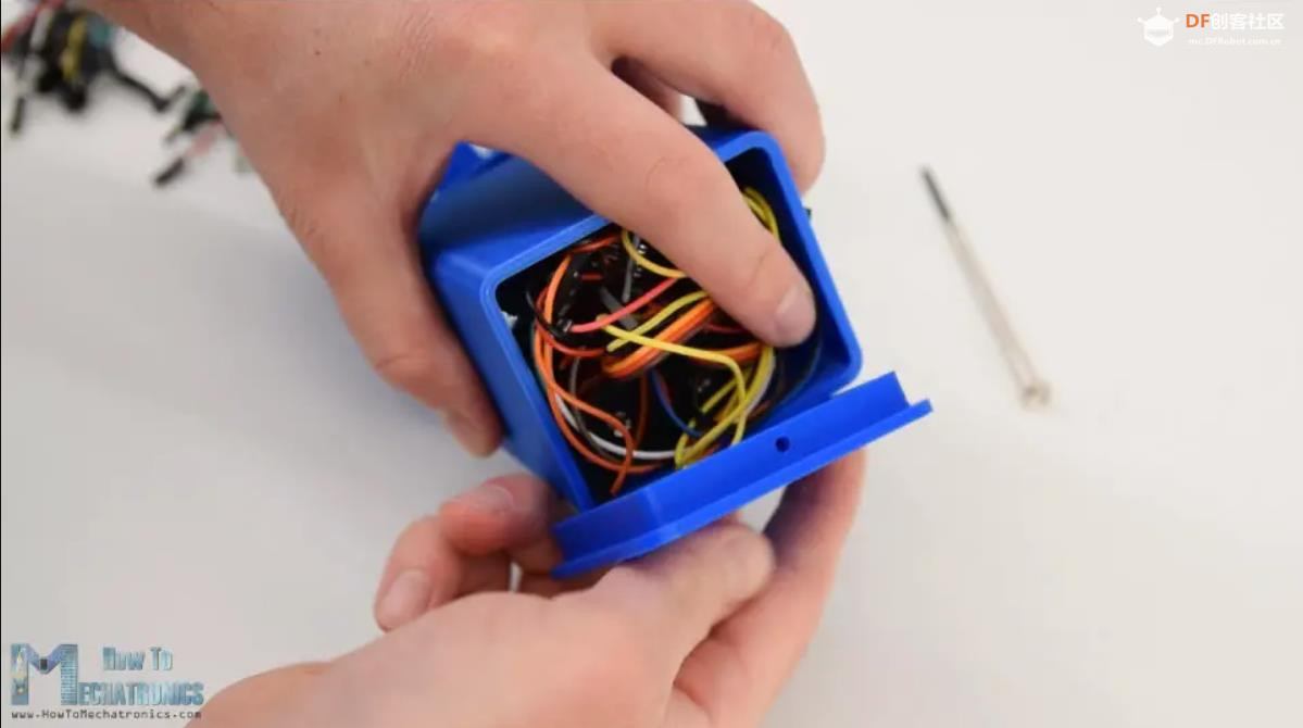
这样,自平衡平台或 Arduino 万向节就完成了,并且按预期运行良好。剩下的就是看看这个程序。
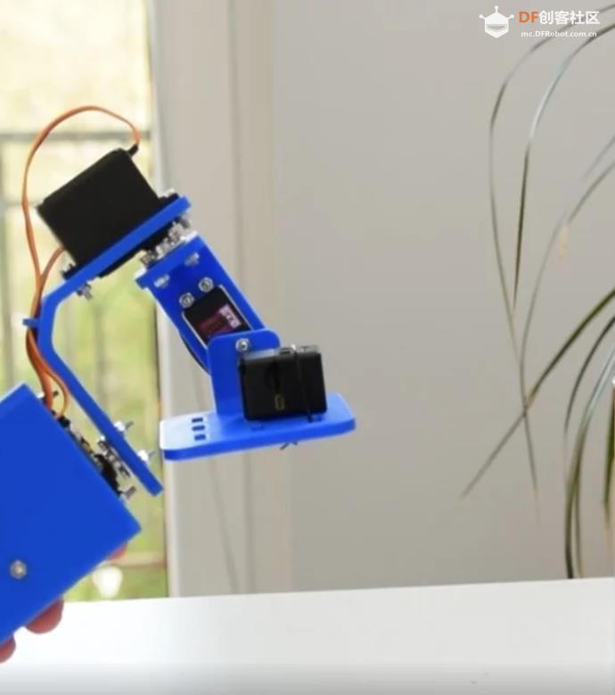
DIY Arduino 云台自稳平台 带 MPU6050 传感器
四、Arduino 代码
此示例的 Arduino 代码是对 Jeff Rowberg 的 i2cdevlib 库中的 MPU6050_DMP6 示例的修改。
开源代码:
- /*
- DIY Gimbal - MPU6050 Arduino Tutorial
- by Dejan, www.HowToMechatronics.com
- Code based on the MPU6050_DMP6 example from the i2cdevlib library by Jeff Rowberg:
- https://github.com/jrowberg/i2cdevlib
- */
- // I2Cdev and MPU6050 must be installed as libraries, or else the .cpp/.h files
- // for both classes must be in the include path of your project
- #include "I2Cdev.h"
-
- #include "MPU6050_6Axis_MotionApps20.h"
- //#include "MPU6050.h" // not necessary if using MotionApps include file
-
- // Arduino Wire library is required if I2Cdev I2CDEV_ARDUINO_WIRE implementation
- // is used in I2Cdev.h
- #if I2CDEV_IMPLEMENTATION == I2CDEV_ARDUINO_WIRE
- #include "Wire.h"
- #endif
- #include <Servo.h>
- // class default I2C address is 0x68
- // specific I2C addresses may be passed as a parameter here
- // AD0 low = 0x68 (default for SparkFun breakout and InvenSense evaluation board)
- // AD0 high = 0x69
- MPU6050 mpu;
- //MPU6050 mpu(0x69); // <-- use for AD0 high
-
- // Define the 3 servo motors
- Servo servo0;
- Servo servo1;
- Servo servo2;
- float correct;
- int j = 0;
-
- #define OUTPUT_READABLE_YAWPITCHROLL
-
- #define INTERRUPT_PIN 2 // use pin 2 on Arduino Uno & most boards
-
- bool blinkState = false;
-
- // MPU control/status vars
- bool dmpReady = false; // set true if DMP init was successful
- uint8_t mpuIntStatus; // holds actual interrupt status byte from MPU
- uint8_t devStatus; // return status after each device operation (0 = success, !0 = error)
- uint16_t packetSize; // expected DMP packet size (default is 42 bytes)
- uint16_t fifoCount; // count of all bytes currently in FIFO
- uint8_t fifoBuffer[64]; // FIFO storage buffer
-
- // orientation/motion vars
- Quaternion q; // [w, x, y, z] quaternion container
- VectorInt16 aa; // [x, y, z] accel sensor measurements
- VectorInt16 aaReal; // [x, y, z] gravity-free accel sensor measurements
- VectorInt16 aaWorld; // [x, y, z] world-frame accel sensor measurements
- VectorFloat gravity; // [x, y, z] gravity vector
- float euler[3]; // [psi, theta, phi] Euler angle container
- float ypr[3]; // [yaw, pitch, roll] yaw/pitch/roll container and gravity vector
-
- // packet structure for InvenSense teapot demo
- uint8_t teapotPacket[14] = { '
-
- [b]代码解读[/b]
-
- 1、获得值后,首先将它们从弧度转换为度数。
-
-
- [code]// Get Yaw, Pitch and Roll values
- #ifdef OUTPUT_READABLE_YAWPITCHROLL
- mpu.dmpGetQuaternion(&q, fifoBuffer);
- mpu.dmpGetGravity(&gravity, &q);
- mpu.dmpGetYawPitchRoll(ypr, &q, &gravity);
-
- // Yaw, Pitch, Roll values - Radians to degrees
- ypr[0] = ypr[0] * 180 / M_PI;
- ypr[1] = ypr[1] * 180 / M_PI;
- ypr[2] = ypr[2] * 180 / M_PI;
-
- // Skip 300 readings (self-calibration process)
- if (j <= 300) {
- correct = ypr[0]; // Yaw starts at random value, so we capture last value after 300 readings
- j++;
- }
- // After 300 readings
- else {
- ypr[0] = ypr[0] - correct; // Set the Yaw to 0 deg - subtract the last random Yaw value from the currrent value to make the Yaw 0 degrees
- // Map the values of the MPU6050 sensor from -90 to 90 to values suatable for the servo control from 0 to 180
- int servo0Value = map(ypr[0], -90, 90, 0, 180);
- int servo1Value = map(ypr[1], -90, 90, 0, 180);
- int servo2Value = map(ypr[2], -90, 90, 180, 0);
-
- // Control the servos according to the MPU6050 orientation
- servo0.write(servo0Value);
- servo1.write(servo1Value);
- servo2.write(servo2Value);
- }
- #endif
2、获得值后,首先将它们从弧度转换为度数。
- // Yaw, Pitch, Roll values - Radians to degrees
- ypr[0] = ypr[0] * 180 / M_PI;
- ypr[1] = ypr[1] * 180 / M_PI;
- ypr[2] = ypr[2] * 180 / M_PI;
3、然后我们等待或进行 300 次读数,因为在此期间传感器仍处于自校准过程中。此外,我们还捕获了 Yaw 值,该值开始时不像 Pitch 和 Roll 值那样为 0,而是始终是某个随机值。
- // Skip 300 readings (self-calibration process)
- if (j <= 300) {
- correct = ypr[0]; // Yaw starts at random value, so we capture last value after 300 readings
- j++;
- }
4、在 300 个读数之后,首先我们通过减去上述捕获的随机值,将偏航设置为 0。然后我们将 Yaw、Pitch 和 Roll 的值从 – 90 度映射到 +90 度,映射到 0 到 180 之间的值,用于驱动伺服系统。
- // After 300 readings
- else {
- ypr[0] = ypr[0] - correct; // Set the Yaw to 0 deg - subtract the last random Yaw value from the currrent value to make the Yaw 0 degrees
- // Map the values of the MPU6050 sensor from -90 to 90 to values suatable for the servo control from 0 to 180
- int servo0Value = map(ypr[0], -90, 90, 0, 180);
- int servo1Value = map(ypr[1], -90, 90, 0, 180);
- int servo2Value = map(ypr[2], -90, 90, 180, 0);
-
- // Control the servos according to the MPU6050 orientation
- servo0.write(servo0Value);
- servo1.write(servo1Value);
- servo2.write(servo2Value);
- }
5、最后使用 write 函数,我们将这些值作为控制信号发送到舵机。当然,如果您只想对 X 轴和 Y 轴进行稳定,您可以禁用偏航舵机,并将此平台用作相机万向节。
请注意,这与好的相机云台相去甚远。运动并不流畅,因为这些伺服系统不是为了这样的目的。真正的相机万向节使用一种特殊类型的 BLDC 电机来实现平稳的运动。因此,仅将此项目视为教育目的。
附录:
项目链接:https://howtomechatronics.com/pr ... abilizing-platform/
项目作者:Dejan
视频教程(13分钟):https://www.youtube.com/watch?v=UxABxSADZ6U&t=6s
MPU6050 教程:https://howtomechatronics.com/tu ... gyroscope-tutorial/
3D打印文件:https://thangs.com/designer/HowT ... ng%20platform-43942
i2cdevlib 库:https://www.i2cdevlib.com/
开源代码:https://howtomechatronics.com/do ... zing-plaftorm-code/
实验场景图 动态图


| 


 沪公网安备31011502402448
 置顶卡
置顶卡 变色卡
变色卡 千斤顶
千斤顶


 萌萌哒新人
萌萌哒新人
 活跃会员
活跃会员
 宣传大使
宣传大使
 牛X认证
牛X认证
 创作达人
创作达人
 ARD DAY
 摸鱼团员
摸鱼团员
 志“童”道合
 编辑选择奖
编辑选择奖


