项目代码
- /* FFT_TEST4
- Ray Burnette 20130810 function clean-up & 1284 port (328 verified)
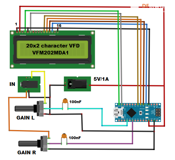
- Uses 2x16 Parallel LCD in 4-bit mode, see LiquidCrystal lib call for details
- http://forum.arduino.cc/index.php?PHPSESSID=4karr49jlndufvtlqs9pdd4g96&topic=38153.15
- Modified by varind in 2013: this code is public domain, enjoy!
- http://www.variableindustries.com/audio-spectrum-analyzer/
- 328P = Binary sketch size: 5,708 bytes (of a 32,256 byte maximum)
- 1284P= Binary sketch size: 5,792 bytes (of a 130,048 byte maximum) Free RAM = 15456
- Binary sketch size: 8,088 bytes (of a 130,048 byte maximum) (Debug)
- */
-
- #include <Wire.h>
- #include <LiquidCrystal.h>
- #include <fix_fft.h>
-
- #define DEBUG 0
- #define L_IN 3 // Audio input A0 Arduino
- #define R_IN 2 // Audio input A1 Arduino
-
- const int Yres = 8;
- const int gain = 3;
- float peaks[64];
- char im[64], data[64];
- char Rim[64], Rdata[64];
- char data_avgs[64];
- int debugLoop;
- int i;
- int load;
-
- LiquidCrystal lcd(12, 11, 5, 4, 3, 2);// RS,E,D4,D5,D6,D7
-
- // Custom CHARACTERS
- byte v1[8] = {
- B00000, B00000, B00000, B00000, B00000, B00000, B00000, B11111
- };
- byte v2[8] = {
- B00000, B00000, B00000, B00000, B00000, B00000, B11111, B11111
- };
- byte v3[8] = {
- B00000, B00000, B00000, B00000, B00000, B11111, B11111, B11111
- };
- byte v4[8] = {
- B00000, B00000, B00000, B00000, B11111, B11111, B11111, B11111
- };
- byte v5[8] = {
- B00000, B00000, B00000, B11111, B11111, B11111, B11111, B11111
- };
- byte v6[8] = {
- B00000, B00000, B11111, B11111, B11111, B11111, B11111, B11111
- };
- byte v7[8] = {
- B00000, B11111, B11111, B11111, B11111, B11111, B11111, B11111
- };
- byte v8[8] = {
- B11111, B11111, B11111, B11111, B11111, B11111, B11111, B11111
- };
-
- void setup() {
-
- if (DEBUG) {
- Serial.begin(9600); // hardware serial
- Serial.print("Debug ON");
- Serial.println("");
- }
-
- lcd.begin(16,2);
- lcd.clear();
- lcd.createChar(1, v1);
- lcd.createChar(2, v2);
- lcd.createChar(3, v3);
- lcd.createChar(4, v4);
- lcd.createChar(5, v5);
- lcd.createChar(6, v6);
- lcd.createChar(7, v7);
- lcd.createChar(8, v8);
-
- for (i=0;i<100;i++)
- {
- for (load = 0; load < i / 5; load++)
- {
- lcd.setCursor(load, 1);
- lcd.write(5);
- }
- if (load < 1)
- {
- lcd.setCursor(0, 1);
- lcd.write(5);
- }
-
- lcd.setCursor(load + 1, 1);
- lcd.write((i - i / 5 * 5) + 1);
- for (load = load + 2; load < 20; load++)
- {
- lcd.setCursor(load, 1);
- lcd.write(9);
- }
- lcd.setCursor(0, 0);
- lcd.print("LOADING.............");
- delay(10);
- }
- lcd.clear();
- delay(10);
- }
-
- void loop() {
-
- for (int i = 0; i < 64; i++) { // 64 bins = 32 bins of usable spectrum data
- data[i] = ((analogRead(L_IN) / 8 ) - 256); // chose how to interpret the data from analog in
- im[i] = 0; // imaginary component
- Rdata[i] = ((analogRead(R_IN) / 8 ) - 256); // chose how to interpret the data from analog in
- Rim[i] = 0; // imaginary component
- }
-
- fix_fft(data, im, 6, 0); // Send Left channel normalized analog values through fft
- fix_fft(Rdata, Rim, 6, 0); // Send Right channel normalized analog values through fft
-
- // At this stage, we have two arrays of [0-31] frequency bins deep [32-63] duplicate
-
- // calculate the absolute values of bins in the array - only want positive values
- for (int i = 0; i < 40; i++) {
- data[i] = sqrt(data[i] * data[i] + im[i] * im[i]);
- Rdata[i] = sqrt(Rdata[i] * Rdata[i] + Rim[i] * Rim[i]);
-
- // COPY the Right low-band (0-15) into the Left high-band (16-31) for display ease
- if (i < 20) {
- data_avgs[i] = data[i];
- }
- else {
- data_avgs[i] = Rdata[i - 20];
- }
-
- // Remap values to physical display constraints... that is, 8 display custom character indexes + "_"
- data_avgs[i] = constrain(data_avgs[i], 0, 9 - gain); //data samples * range (0-9) = 9
- data_avgs[i] = map(data_avgs[i], 0, 9 - gain, 0, Yres); // remap averaged values
- }
-
- Two16_LCD();
- decay(1);
- }
-
- void Two16_LCD() {
- lcd.setCursor(0, 0);
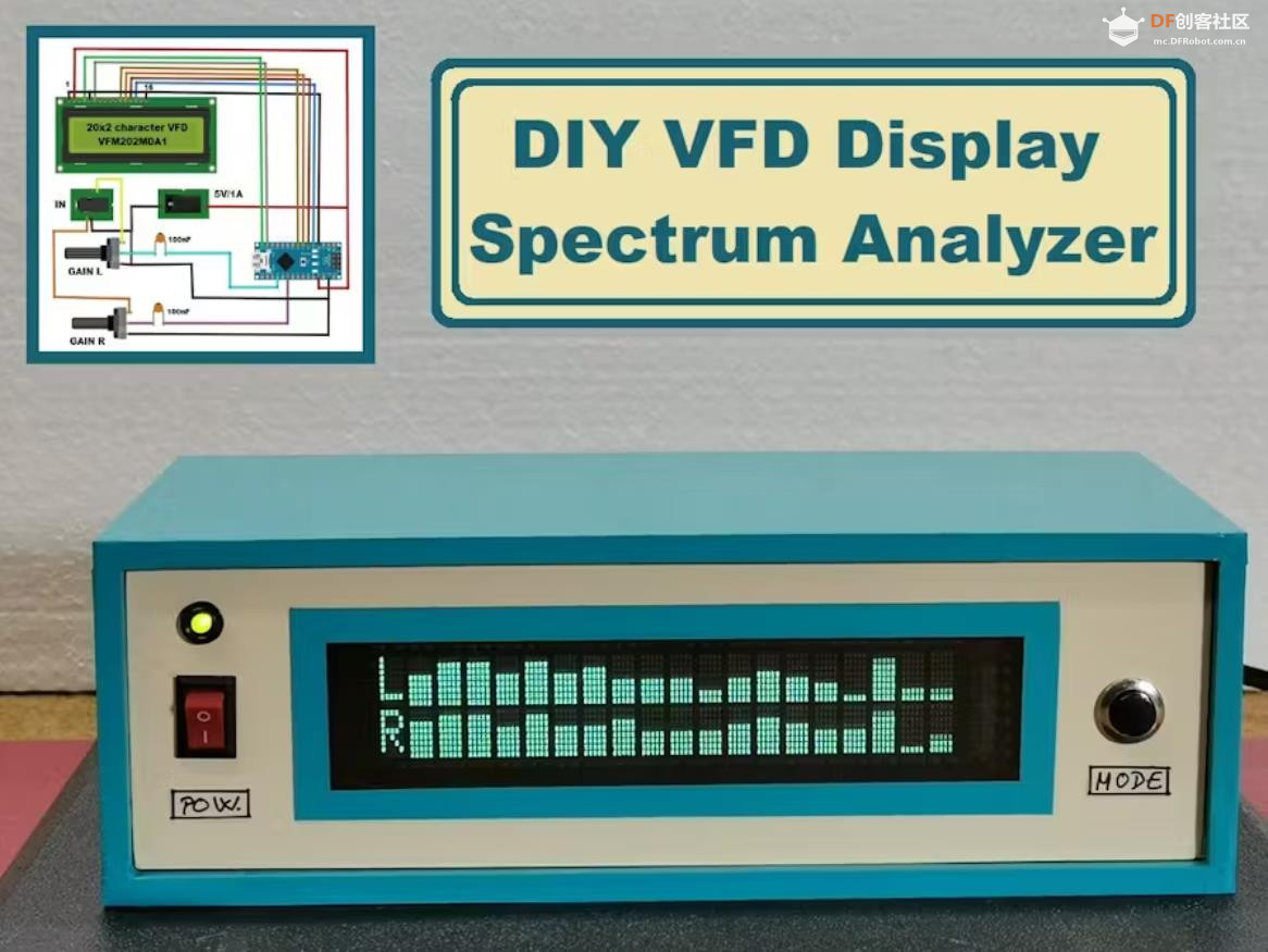
- lcd.print("L"); // Channel ID replaces bin #0 due to hum & noise
- lcd.setCursor(0, 1);
- lcd.print("R"); // ditto
-
- for (int x = 1; x < 20; x++) { // init 0 to show lowest band overloaded with hum
- int y = x + 20; // second display line
- if (data_avgs[x] > peaks[x]) peaks[x] = data_avgs[x];
- if (data_avgs[y] > peaks[y]) peaks[y] = data_avgs[y];
-
- lcd.setCursor(x, 0); // draw first (top) row Left
- if (peaks[x] == 0) {
- lcd.print("_"); // less LCD artifacts than " "
- }
- else {
- lcd.write(peaks[x]);
- }
-
- lcd.setCursor(x, 1); // draw second (bottom) row Right
- if (peaks[y] == 0) {
- lcd.print("_");
- }
- else {
- lcd.write(peaks[y]);
- }
- }
-
- debugLoop++;
- if (DEBUG && (debugLoop > 99)) {
- Serial.print( "Free RAM = " );
- Serial.println( freeRam(), DEC);
- Serial.println( millis(), DEC);
- debugLoop = 0;
- }
- }
-
-
- int freeRam () {
- extern int __heap_start, *__brkval;
- int v;
- return (int) &v - (__brkval == 0 ? (int) &__heap_start : (int) __brkval);
- }
-
-
- void decay(int decayrate) {
- int DecayTest = 1;
- // reduce the values of the last peaks by 1
- if (DecayTest == decayrate) {
- for (int x = 0; x < 40; x++) {
- peaks[x] = peaks[x] - 1; // subtract 1 from each column peaks
- DecayTest = 0;
- }
- }
-
- DecayTest++;
- }
|


 沪公网安备31011502402448
 置顶卡
置顶卡 变色卡
变色卡 千斤顶
千斤顶
 萌萌哒新人
萌萌哒新人
 活跃会员
活跃会员
 宣传大使
宣传大使
 牛X认证
牛X认证
 创作达人
创作达人
 ARD DAY
 摸鱼团员
摸鱼团员
 志“童”道合
 编辑选择奖
编辑选择奖


